

Simulation of mould filling process using smoothed particle hydrodynamics
HE Yi, ZHOU Zhao-yao, CAO Wen-jiong, CHEN Wei-ping
School of Mechanical and Automotive Engineering, South China University of Technology, Guangzhou 510640, China
Received 5 November 2010; accepted 20 April 2011
Abstract:
The implementation of high pressure die casting (HPDC) filling process modeling based on smoothed particle hydrodynamics (SPH) was discussed. A new treatment of inlet boundary was established by discriminating fluid particles from inlet particles. The roles of artificial viscosity and moving least squares method in the present model were compared in the handling pressure oscillation. The final model was substantiated by simulating filling process in HPDC in both two and three dimensions. The simulated results from SPH and finite difference method (FDM) were compared with the experiments. The results show the former is in a better agreement with experiments. It demonstrates the efficiency and precision of this SPH model in describing flow pattern in filling process.
Key words:
high pressure die casting (HPDC); smoothed particle hydrodynamics (SPH); filling process; moving least squares method;
1 Introduction
As a kind of near net shape manufacturing process, high pressure die casting (HPDC) is characterized by its high strength and good performance. Due to its high volume and low cost, it is extensively used in automobile, electronics and other appliance industries. In the filling process, liquid metal is injected into the die under high pressure and high velocity, companied with the geometric complexity, an intricate flow pattern may be presented. The quality and process productivity are essentially determined by the filling sequence of the liquid metal. The flow pattern is very critical to the die because it will affect the amount of the entrapped voids and the forming of homogenous cast components. Numerical simulation plays a valuable role in offering insight into the filling process, which can greatly enhance design efficiency and shorten product development cycle [1].
Modeling the mould filling process in HPDC is the beset with difficulties as accurate modeling of the location of free surface and other interrelated phenomena. For decades, grid and mesh based numerical methods such as finite difference method (FDM), finite volume method (FVM) and finite element method (FEM) have been widely researched in casting simulation. Volume of fluid (VOF) method proposed by HIRT and NICHOLS is the most common method used for tracking of free surface in Euler techniques, in which a color function is employed to represent the volume fraction of fluid in each computational mesh. However, the reconstruction of volume fraction always leads to numerical oscillations. For the Lagrangian techniques like FEM, extremely large deformation requires special techniques like mesh rezoning, which is time-consuming and usually cannot acquire satisfactory results [2].
Over the past decades, smoothed particle hydrodynamics (SPH) has been extended from solving astrophysics problem to computational fluid dynamics by MONAGHAN and GINGOLD [3-5]. Because of its Lagrangian nature, it can track free surface automatically. In SPH, the system is represented by a set of particles, which possess material properties and interact with each other in the range of a smooth length. It has been widely used in various branches in science and engineering based on its strong ability to incorporate complex physics into the SPH formulations. Recently, the applications of SPH include the coastal hydrodynamics including water wave impact [6], hypervelocity impact [7], free surface flow [5], multi-phase flows [8], high explosive detonation and explosion, heat and/or mass conduction [9]. CLEARY et al [10]. used SPH to simulate metal forming and first introduced it into the casting process successfully. However, even though SPH has been involved in a myriad of applications and the results were pretty good compared with traditional grid and mesh based numerical methods, the precision of the simulation is still suffering from the influence of pressure oscillation and the distribution of particles, which could be improved by introducing some modifications into the model.
In the present study, a brief description of SPH methodology is presented and some important issues in implementation are elaborated. A new treatment of inlet boundary is presented by distinguishing fluid particles from inlet particles. The roles of artificial viscosity and moving least squares method in handling pressure oscillation are contrasted and they are used in the present method. We validate the method by comparisons with the experimental results supplied by SCHMID and KLEIN [11] and the FDM simulation results.
2 Methodology
2.1 Integral interpolation
Similar to other mesh free particle methods, the computational frames in SPH are the particles. Every particle in the SPH is associated with a support domain. The SPH approximation, which consists of the kernel approximation and the particle approximation, is performed within the current support domain. The SPH is based on integral interpolation that allows any physical quantity f(r) to be derived from a set of neighbor particles via the kernel approximation:
![]() (1)
(1)
where r and r�� are the position vectors; �� is the solution space that depends on a smoothing length h; W is called the kernel function, which is very crucial to the SPH formulation and its form is an approximation to delta function. The approximation given in Eq. (1) is easily shown as second-order accurate with respect to h: ![]() when W satisfies the conditions listed in Ref. [12]. Though particle approximation, Eq. (1) can be converted to the discrete form (Eq. 2) of summation over the particles in the support domain.
when W satisfies the conditions listed in Ref. [12]. Though particle approximation, Eq. (1) can be converted to the discrete form (Eq. 2) of summation over the particles in the support domain.
![]() (2)
(2)
where the index j denotes the particle label and the particle j within the support domain carries the properties such as mass mj, density ��j, and velocity vj at the position rj.
Following the same argument, the spatial derivative of the physical quantity f (r) is given by
![]() (3)
(3)
2.2 Kernel function
The performance of SPH method depends strongly upon the choice of the kernel function. It determines both the dimension of the support domain and the numerical efficiency of the SPH approximation. Some studies [2, 12] indicate that the stability of the SPH method rests on the second derivative of the kernel function. In the present studies, the following spline kernel function proposed by MONAGHAN [4] was adopted.
 (4)
(4)
where ��d is 1/h, 15/7��h2, 3/2��h3 in one-, two- and three-dimensional spaces, respectively; R is the relative distance between two particles, R=x/h, where x is the distance between two particles and h is the smoothing length. Its first and second derivatives are continuous, which means that the performance of SPH approximation is not too sensitive to particle disorder. However, its second derivative is piecewise linear function, the stability properties can be inferior to other smoother kernels [12].
An important feature of kernel function is that its support domain is always selected as ��h, which is the size of support domain, where �� is the proportionality factor. And the smoothing length is always proportional to the initial particle spacing, so that each particle interacts with a finite number of neighbor particles within its support domain (see Fig. 1).
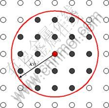
Fig. 1 Set of neighbor particles of 2D simulation
3 Numerical model
3.1 Governing equations
Metal filling in HPDC process is a complex process where flow pattern is governed by the Navier-Stokes equations. The approximate numerical solutions are calculated on the particles which represent the liquid metal in the die. Based on the SPH approximation, the SPH representation of governing equations will be given in the following.
The density of particle i can be evaluated over the particle in its support domain. The most frequently used continuity density equation is obtained as [4]
![]() (5)
(5)
where the indexes i, j, respectively, denote variable at the particles i, j, respectively; ��ij is the velocity vector: ��ij=��i-��j; Wij is the kernel function. This form of the continuity equation does not conserve the mass exactly. However, it would not suffer the boundary particle deficiency and need less computational efforts compared with summation density method.
Following the same argument, the standard SPH form for the momentum equation can be written as follows [12]:
![]()
![]() (6)
(6)
It is the symmetric SPH forms for the momentum equation, which could reduce errors arising from the particle inconsistency problem. The right hand side consists of the pressure term, viscous force and body force. In Eq. (6) p and �� denote the pressure and viscosity at particles; �� is the shear strain rate. For the liquid metal flow in HPDC, the total shear stress �� should be proportional to the shear strain rate through the dynamic viscosity ��; f denotes the body force; ��ij is the artificial viscosity term for enhancing the stability properties of numerical algorithms and takes the following form [5]:
 (7)
(7)
3.2 State of equation
Theoretically, we considered the liquid metal under high temperature in HPDC weakly compressible fluid. In the SPH methodology, the particle motion is driven by the pressure gradient. In every time step, the pressure is calculated and then passes to the momentum equation (Eq. (6)). In SPH simulation, the pressure is calculated through using a quasi-incompressible equation of state (Eq. (8)). In practical application, the following equation of state proposed by MONAGHAN [5] is applied to model flow in the die:
 (8)
(8)
where ��=7; ��0 is the reference density; B is the magnitude of the pressure, which is chosen to ensure the maximum density oscillation less than 1% around the reference density. It can be seen from the equation that a very small oscillation in density may lead to a large variation in pressure.
4 Implementation
The filling process of SPH simulation is implemented in FORTRAN computer program. The flow chart is presented in Fig. 2
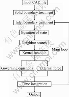
Fig. 2 Flow chart of SPH in HPDC process
The whole implementation can be divided into three parts: pre-process, calculation and post-process. The flow chart displayed here is mainly about the calculation. The inputted CAD file was treated by a mesh generator to produce meshes and using the nodal points of the meshes as the initial set-up for SPH particles. Some of the subjects in implementation are discussed below.
4.1 Boundary treatment
4.1.1 Solid boundary treatment
SPH is a continuum scale particle method, the field variables need to be directly calculated on the boundary. Due to the complexity of the die, the ideal boundary in the simulation of HPDC plays a role in not only preventing fluid from penetrating solid walls but also ensuring that the intricate walls of the die could be represented precisely [10]. The implementation of the boundary condition in HPDC simulation is not as straightforward as that in the grid based method. It is common to represent solid boundary by a set of particles. Some schemes have been proposed [2]. Solid boundaries are often modeled with fix boundary particles and artificial repulsive force or alternatively with mirror particles. However, because of the complexity of the model, it is not easy to construct mirror particles that obtained through reflecting the real fluid particles along the solid boundary. In our work, the virtual particles used are located right on the solid boundary and are similar to what MONAGHAN used [5]. These particles produce a repulsive boundary force that takes the form similar to Lennard-Jones molecular force.
 (9)
(9)
where the parameters n1 and n2 are usually taken as 12 and 4, respectively; D is a problem dependent parameter, and has the unit of square of the maximum velocity. The cutoff distance r0 is an important parameter which determines the influence distance of the repulsive force. It is usually set to be the initial particle space.
4.1.2 Inlet boundary treatment
The efficiency of the computation is limited by the total number of particles used in the simulation. It can enhance the efficiency obviously by only modeling the die, the gate, and the runner without considering the flow pattern before the liquid metal coming into the runner system. Our current scheme, which is flexible and applicable, is to model the fluid particles by two parts, which consist of the inlet particles and initial fluid particles. The particles are generated by the inlet boundary then injected into the computational domain until the entire system reaches equilibrium (Fig. 3).
The inlet boundary particles, which are composed of inlet virtual particles and inlet control particles, have the same velocity according to specific circumstances. When the inlet control particles move to the control line, the entire inlet boundary particles are set back to their initial position and a line of new fluid particles are generated at the control line with the properties that belong to the inlet control particles. The inlet control particles interact with the fluid particles, and then these particles produce a repulsive force according to the formation of Eq. (9). The repulsive force could prevent the fluid particles from crossing the inlet boundary when the pressure becomes very high. The inlet virtual particles are used here. They are regularly distributed at the initial state and have the same velocity through the simulation. And these virtual particles take part in the SPH approximation of the fluid particles. The particle deficiency problem can be somewhat remedied. The number of inlet virtual particles layers is decided from the radius of the compact support.

Fig. 3 Configuration of inlet boundary condition
4.2 Neighbor search
The most time-consuming part in the SPH simulation is to find the neighbor particles. Each particle has a finite number of particles within its compact support which is a circle in 2D or a sphere in 3D with radius of ��h. Global search method, linked list search and tree search method are popular in SPH simulation. The linked list search is adopted in the present study. It has good performance in the case of constant smoothing length. The complexity of linked list search is of the order O(N) [12].
4.3 Time integration
As an explicit hydrodynamic method, different time integration schemes have been employed in SPH, such as the leapfrog algorithm, the predictor-corrector algorithm, the Runge-Kutta algorithm and Beeman algorithm. In the present study, the leapfrog algorithm [12], because of its low requirement on memory storage and its higher computational efficiency, is adopted. Detailed realization process is discussed as follows:
 (10)
(10)
where t0 is the initial time; D��i(t0) and D��i(t0) denote the change in density and velocity, respectively. At the first time step, the density and velocity are advanced at half a time step, while the particle positions are advanced in a full time step.
At each subsequent time step, the density and velocity of each particle need to be predicted according to Eq. (11) at half a time step to coincide the position in the beginning of each time step.
 (11)
(11)
After the loop, the density, position, and the velocity are calculated according to Eq. (12).
 (12)
(12)
Finally, the pressure is calculated from density using the equation of state Eq. (8). By using the standard leapfrog algorithm, second order accuracy in time is achieved. Because the leapfrog algorithm is conditionally stable, the time step is chosen according to the CFL condition, stating that the maximum rate of propagation of information numerically must exceed the physical rate. In SPH, it means
![]() (13)
(13)
Taking into account the viscous dissipation and the external force, a variable time step is calculated [12].
 (14)
(14)
where fi is a force per unit mass,  ,
, ![]() and
and ![]() . Combine these equations together with two corresponding safety coefficients,
. Combine these equations together with two corresponding safety coefficients,
![]() (15)
(15)
where ��1=0.4 and ��2=0.25 are suggested [5].
5 Results and discussion
5.1 Filling of 2D model
In order to validate our SPH method, the effectiveness was investigated by comparison with the simulation of FDM and the water analogue experiment which was performed by SCHMID and KLEIN [11] on a cold chamber die-casting machine. The experiment was carried out using colored water at room temperature. Due to the similarity of kinematic viscosity between liquid aluminum and water, water analogue experiment provides a feasible way to investigate the mould filling process [13]. Generally, the CAD file of a casting component from industry is used as input in casting simulation. The thickness of the die in the third dimension is 2 mm and the gate velocity is 8.7 m/s. Figure 4 illustrates the die used in the experiment. In this comparison, a die consisted of a series of right angled and circular bends, which was filled with water.

Fig. 4 Schematic diagram of S-shaped channel water analogue experiment (Unit: mm)
As stated previously, when the particles approach to the boundary and the free surface, the support domain of the kernel of these particles is not complete. This will introduce errors in the density computation and then the pressure field will suffer large oscillation.
In order to make the computation stable, several modifications have been implemented in the present method. A moving least squares (MLS) approach, proposed by COLAGROSSI and LANDRINI [14], can exactly reproduce linear variations in the density field if used at every time step. So, this modification is used to reinitialize the density field every 30 time steps.
![]() (16)
(16)
The corrected kernel ![]() is found in 2D to be
is found in 2D to be
![]()
![]() (17)
(17)
And the corrected vector is given by
 (18)
(18)
![]() (19)
(19)
 (20)
(20)
The first test case presented here is to demonstrate the performance of SPH with MLS and artificial viscosity. The HPDC simulation is carried out in the S-shaped mould. After the impact of the liquid metal front against the vertical wall at the low curved region, the evolution of pressure field is presented in Fig. 5.

Fig. 5 Pressure fields with four different modifications: (a) No artificial viscosity and no MLS; (b) Only artificial viscosity; (c) Only MLS; (d) Artificial viscosity and MLS
A resolution of 1.25 particles per millimeter was used in the simulation. The solution in Fig. 5(a) was obtained without any modifications. Large oscillation which may destroy the calculation can be found in the figure. Although the total energy is conserved well, the particles are prone to splash when the impact happens. As presented in the solution in Fig. 5(b), when the artificial viscosity is introduced into the momentum equation, the pressure oscillation can be largely reduced. However, the total energy of the system is not conserved. With the density filter used in the solution in Fig. 5(c), more regular pressure distribution can be obtained and the particles distribution is improved. The solution in Fig. 5(d) demonstrates a combination of artificial viscosity and MLS density filter, not only can a more regular pressure field be obtained but also the disadvantage of the artificial viscosity is somewhat relieved.
To make the particles move more orderly, the revised XSPH technology proposed by MONAGHAN [15] is used in the simulation.
![]() (21)
(21)
where �� is a constant in the range of 0�ܦš�1, and ��=0.3 is used; ![]() when the particle i moves with a velocity close to the average velocity in its neighborhood. The contribution from the neighboring particles is included through this technology.
when the particle i moves with a velocity close to the average velocity in its neighborhood. The contribution from the neighboring particles is included through this technology.
The comparison between the simulation results by present method with the experimental results of SCHMID and KLEIN [11] and the simulation results by finite difference method at four specific times are given in Table 1. The FDM method, based on the volume of fluid (VOF) approach, is used to solve the coupling between the momentum and mass conversation equations and to treat the free surface.
In the SPH simulation, a resolution of 1.25 particles per millimeter was used, giving a total of 51411 particles. In FDM calculation, the grid size is selected as 1 mm. Particularly, there are several corners in the geometry of the die, which could make the flow pattern intricate and cause air trapped within the die. When t=7.15 ms, the SPH solution and the FDM solution capture quite well the shape of the flow, and SPH result is very close to the experiment even at the flow front but FDM not. The details are not presented in the FDM solution. When t=25.03 ms, both of the simulations are able to estimate the overall shape of the flow and somewhat fragmented nature of the free surface is also predicted. The void location near the lower curved region is right predicted, but there are slight under-prediction of the size of the void in the curved region and sight over-prediction of the void width in the first horizontal section. However, the SPH solution is better predicted compared with the FDM method. At 39.34 ms, the SPH result compares very well to the experiment, and there is close agreement in the shape of flow front in the third vertical section and the height of the free surface is quite similar to the experiment. The void in the lower curved region and a void besides the first vertical wall are slightly under-predicted. Two bubbles can be seen near the bottom wall of the horizontal section of the die, the voids do exist in the same region but their size is much bigger than that in the experiment. However, compared with the result of FDM method, the voids are not predicted. In the second horizontal section, there is slight under-prediction of the fluid width in SPH solution, but the FDM does not capture the fluid shape. At 53.64 ms, voids exit in the second horizontal section in both of the numerical simulation. The revolution bubbles in the lower curved region and the first vertical section have disappeared in the SPH solution. In the experiment, these larger bubbles beside the second vertical wall and the lower curved region are likely the air entrapped in these regions and cannot be predicted by SPH and FDM methods. At the end of the die, due to the lack of clarity of the experimental photograph, a valid contrast cannot be made between SPH and FDM. However, the detail of the free surface is better predicted by SPH at the parts.
Table 1 Comparison between SPH results, Schmid experimental results and FDM results

5.2 Filling of 3D model
As an example to validate the SPH formulations and to demonstrate its ability to simulate real industrial HPDC process in three dimensions, the present method is applied to model flows in two simple dies with different runner systems but the computational demand increases drastically. The models can be seen in Fig. 6. The treatment of gate, due to its smaller dimension compared with other components, may be the most difficult part in the simulation of three-dimensional HPDC.

Fig. 6 Three-dimensional models in simulation: (a) Model 1; (b) Model 2
Both of the inlet velocities are 9 m/s and the patterns of filling are shown in Fig. 7 and Fig. 8. Visualization of particle system is quite difficult, and two kinds of visualization are presented. It can be seen from the results that SPH can easily extend to three- dimensional HPDC simulation.

Fig. 7 Simulation results of model 1: (a) 0.015 s; (b) 0.03 s; (c) 0.045 s; (d) 0.06 s

Fig. 8 Simulation results of model 2: (a) 0.008 s; (b) 0.017 s; (c) 0.030 s; (d) 0.061 s
6 Conclusions
1) The SPH method was applied to simulating the filling process in HPDC. It is very effective in dealing with large deformation of free surface flow. This provides a detailed examination of the free surface in the mould. The methodology and implementation were discussed in detail.
2) A new treatment of inlet boundary which is composed of inlet virtual particles and inlet control particles was proposed. It can enhance the computational efficiency obviously. The MLS approach accompanied artificial viscosity was investigated which could make the computation stable and reduce the pressure oscillation largely. XSPH was applied to making the particles move more orderly.
3) Based on the developed method, an S-shaped benchmark test was investigated through comparison with results obtained by the FDM and the experimental results supplied by SCHMIDT and KLEIN [11]. The calculation results obtained by SPH are in good agreement with the available experimental results. As an example to demonstrate its ability in simulating real industrial HPDC process, the present method was applied to three-dimensional filling processes in HPDC process. The ability of SPH to produce reasonable results in simulating filling process in HPDC process is shown through this study.
References
[1] CLEARY P W, HA J, PRAKASH M, NGUYEN T. 3D SPH ?ow predictions and validation for high pressure die casting of automotive components [J]. Applied Mathematical Modelling, 2006, 30: 1406-1427.
[2] LIU M B, LIU G R. Smoothed particle hydrodynamics (SPH): An overview and recent developments [J]. Arch Comput Methods Eng, 2010, 17: 25-76.
[3] MONAGHAN J J, GINGOLD R A. Shock simulation by the particle method SPH [J]. J Comput Phys, 1983, 52: 374-389.
[4] MONAGHAN J J. Smoothed particle hydrodynamics [J]. Ann Rev Astronom Astrophys, 1992, 30: 543-574.
[5] MONAGHAN J J. Simulating free surface flow with SPH [J]. Journal of Computer Physics, 1994, 110: 399-406.
[6] DALRYMPLE R A, ROGERS B D. Numerical modeling of water waves with the SPH method [J]. Coastal Engineering, 2006, 53: 141-147.
[7] PAUL H L. Groenenboom. numerical simulation of 2D and 3D hypervelocity impact using the SPH option in pam-shock [J]. Int J Impact Engng, 1997, 20: 309-323.
[8] HU X Y, ADAMS N A. An incompressible multi-phase SPH method [J]. Journal of Computational Physics, 2007, 227: 264�C278.
[9] CLEARY P W, MONAGHAN J J. Conduction modelling using smoothed particle hydrodynamics [J]. Journal of Computational Physics, 1999, 148: 227�C264.
[10] CLEARY P W, HA J, ALGUINE V, NGUYEN T. Flow modelling in casting processes [J]. Applied Mathematical Modelling, 2002, 26: 171-190.
[11] SCHMID M, KLEIN F. Fluid flow in die-cavities: Experiments and numerical simulation [C]//The 18th International Die Casting Congress and Exposition Indianapolis. Indianapolis: NADCA, 1995: 93-97.
[12] LIU G R, LIU M B. Smoothed particle hydrodynamics, a meshfree particle method [M]. Singapore: World Scienti?c, 2003.
[13] ZHAO Zhong-xing, WANG Song-tao, WEN Shao-ling, ZHAI Yu-chun. Computer video technology of water simulation for aluminum liquid filling process [J]. The Chinese Journal of Nonferrous Metals, 2005, 15(8): 1262-1266. (in Chinese)
[14] COLAGROSSI A, LANDRINI M. Numerical simulation of interfacial ?ows by smoothed particle hydrodynamics [J]. Journal of Computational Physics, 2003, 191: 448�C475.
[15] MONAGHAN J J. On the problem of penetration in particle methods [J]. J Comp Phys, 1989, 82: 1-15.
ģ�߳������й⻬�������嶯��ѧģ��
�� ��, ����ҫ, ������, ��άƽ
����������ѧ ��е����������ѧԺ������510640
ժ��Ҫ�������˻��ڹ⻬�������嶯��ѧ(SPH)��ѹ������ģ���ʵʩ���̡�������һ�������������Ӻ��������ӵ������߽����������˹��Ⱥ��ƶ���С���˷��ڴ���ѹ�����е����ý����˶Աȡ�������ģ����ģ��ѹ����ά����ά�ij����̽�������֤����SPH������ֵ�ģ������ʵ���������˶Ա��о��������ʾSPH��ʵ���Ϊ�Ǻϣ�������SPH��������������̬�������Ч���뾫�ȡ�
�ؼ��ʣ�ѹ�����⻬�������嶯��ѧ�������̣��ƶ���С���˷�
(Edited by LI Xiang-qun)
Foundation item: Project (2009Z001) supported by the Important Item in Guangdong-Hong Kong Key Project, China; Project (2010B090400297) supported by the Cooperation Project in Industry, Education and Research of Guangdong Province and Ministry of Education of China
Corresponding author: ZHOU Zhao-yao; Tel: +86-20-87112948-303; E-mail: zhyzhou@scut.edu.cn
DOI: 10.1016/S1003-6326(11)61111-4
Abstract: The implementation of high pressure die casting (HPDC) filling process modeling based on smoothed particle hydrodynamics (SPH) was discussed. A new treatment of inlet boundary was established by discriminating fluid particles from inlet particles. The roles of artificial viscosity and moving least squares method in the present model were compared in the handling pressure oscillation. The final model was substantiated by simulating filling process in HPDC in both two and three dimensions. The simulated results from SPH and finite difference method (FDM) were compared with the experiments. The results show the former is in a better agreement with experiments. It demonstrates the efficiency and precision of this SPH model in describing flow pattern in filling process.
