
Trans. Nonferrous Met. Soc. China 30(2020) 2669-2680
Effect of Al-foil addition on microstructure and temperature field of laser fusion welded joints of DP590 dual-phase steel and AZ31B magnesium alloy
He ZHOU1,2, Jin-shui LIU1,2, Dian-wu ZHOU2, Tao TAO1,2
1. College of Materials Science and Engineering, Hunan University, Changsha 410082, China;
2. State Key Laboratory of Advanced Design and Manufacturing for Vehicle Body, Hunan University, Changsha 410082, China
Received 22 October 2019; accepted 27 September 2020
Abstract:
The experiments of laser fusion welding with Al-foil addition was carried out for DP590 dual-phase steel and AZ31B magnesium alloy in an overlap steel-on-magnesium configuration. Temperature field was simulated by COMSOL finite element software for steel/magnesium laser fusion welding. The results show that when Al-foil is added, some defects, such as pores, cracks and softening in heat affected zone (HAZ), can be avoided in welding joint, the bonding strength of steel/magnesium joints is increased, heat transfer between steel and magnesium is regulated. In the case of adding Al-foil, welding pool is divided into two parts, the upper and lower pools contact each other but do not mix, the transition layer at the interface between the upper and lower molten pools mainly contains Al-Fe phases, such as AlFe, Al2Fe and AlFe3, and these new phases are helpful for promoting the metallurgical connection between the upper and lower molten pools. Hence, adding Al-foil laser fusion welding is an effective way in joining steel to magnesium alloy.
Key words:
dissimilar metal welding; microstructure; numerical simulation; Al-foil;
1 Introduction
Magnesium alloy is applied in the field of modern transportation, known as the 21st century green engineering materials. Steel is widely used in the car body components as a traditional material in the automotive industry. Hence, it is inevitable for steel and magnesium connection [1-3]. However, it is difficult for joining steel to magnesium alloy due to the melting and boiling point difference, no solid solutions or intermetallic compound (ICM). In order to find an effective welding method, various studies have been conducted for steel/magnesium dissimilar metal laser welding. TAN et al [4] and LI et al [5] have welded magnesium and steel by the use of laser brazing technology, and found that the wettability, spread of magnesium on steel and the joint strength were increased by adding nickel and zinc coatings. SONG et al [6,7] and LIU et al [8,9] have welded steel and magnesium using laser arc hybrid welding technology. They suggested that some defects were reduced by controlling welding parameters, and indicated that metallurgical connection between steel and magnesium could be strengthened by adding inter-layer. SONG et al [10] also thought that inter-layer played an important role in welded joints for steel and magnesium welding with composite heat sources. SHEN et al [11] reported that the penetration of laser welding can be increased based on magnesium alloy. WINDMANN et al [12] found that the bonding area was increased by induction preheating and flux for steel/magnesium laser welding. CASALINO et al [13] have studied the offset fiber laser welding of AZ31 magnesium alloy to the 316 stainless steel, which proves that this technology has the potential to weld magnesium/steel. But local overheating is often caused due to the direct contact between steel and magnesium during welding. Friction stir welding (FSW) is a new method which is suitable for welding dissimilar metals. Some achievements have been made in welding steel and magnesium. CHEN and NAKATA [14] used friction stir welding to weld steel and magnesium. They concluded that the surface state of steel has a significant impact on the welding strength. Steel with zinc coating has higher strength when welded with magnesium. WANG et al [15] conducted friction stir welding of magnesium alloy and steel, and they found that alloy elements in the two alloys diffused to the interface and formed alloy element aggregation zone. In addition, there were also many spot welding methods for magnesium and other metals, such as resistance spot welding [16,17] and ultrasonic spot welding [18]. Sufficient heat and pressure during spot welding are beneficial to the welding of magnesium and other metals. However, until now, as far as the above welding methods of steel/magnesium were concerned, the two base materials were not melted at the same time.
In our previous studies [19], the effect of Sn-foil addition on steel/magnesium laser welding was investigated, and the results showed that the temperature field was regulated and the metallurgical connection of steel/magnesium was promoted. In this work, the experiments of laser fusion welding with Al-foil addition were carried out for DP590 dual-phase steel and AZ31B magnesium alloy in an overlap steel-on-magnesium configuration. Morphology, element distribution, phase composition and mechanical properties of the weld were analyzed by the polarizing microscope, SEM equipped with EDS, XRD and universal material testing machine, respectively. In addition, finite element model of steel/magnesium laser fusion welding was established, and the distribution of temperature field and flow field in welding process were analyzed. The behavior of molten pool and the bonding mechanism of welded joints in welding process were obtained by combining experiment with simulation analysis. Through the research, the project results will provide new idea and theoretical basis for melting welding between steel and magnesium dissimilar metals, and it is conducive to expanding the industrial application of magnesium alloys.
2 Experimental
2.1 Materials and experimental procedure
DP590 dual-phase steel and AZ31B magnesium alloy were selected as experimental materials in this work, and DP590 dual-phase steel was not galvanized. Their sizes were 100 mm �� 30 mm �� 1.4 mm and 100 mm �� 30 mm �� 1.5 mm, respectively. Steel sheet was placed on magnesium sheet in an overlap configuration. Al-foil, 1060 aluminum alloy, 100 mm �� 30 mm �� 0.3 mm in size, was added between two sheets as inter-layer. The chemical compositions of the base metals and inter- layer are listed in Table 1. The properties of magnesium and steel at room temperature are listed in Table 2. Welding configuration is shown in Fig. 1. The weldment was composed of three layers, the upper layer was a steel plate, the middle layer was Al-foil and the bottom layer was a magnesium plate. On one hand, the reflectivity of steel to laser was smaller than that of magnesium, steel was first melted under direct laser irradiation, and heat was transferred to the magnesium plate through the intermediate layer. On the other hand, steel sinks under the influence of gravity and magnesium floats up under the influence of buoyancy, which is beneficial to the metallurgical combination of steel and magnesium. The three-layer metal sheet was clamped by the clamping device and then subjected to laser welding experiments.
Table 1 Compositions of welding base material and inter-layer (wt.%)
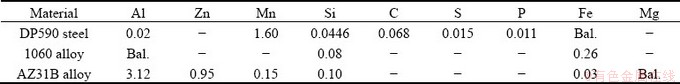
Table 2 Properties of magnesium and steel
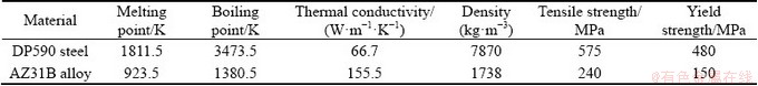
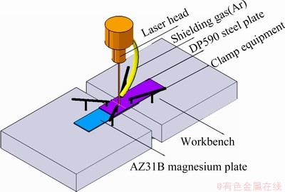
Fig. 1 Sketch of experimental set-up
The experiment was carried out using a 4 kW fiber laser (YLS-4000-CL) with beam wavelength of 1070 nm. The beam was focused to obtain a spot size of 0.4 mm by the use of focusing mirror with a 200 mm focal length. The laser mode was TEM00 and the angle alpha of beam divergence was less than 0.15 rad. Argon was used as the shielding gas to prevent oxidation of the metal sheets. A good weld was achieved based on adjusting welding parameters. Welding speeds were in the range of 1800-2100 mm/min and welding powers were in the range of 1800-2200 W. After welding, tensile- shear strength of the joints were tested by universal material testing machine. Then, the welded joints were cut into small pieces by WEDM. After grinding and polishing these small samples, the steel side of the welded joint was etched by nital acid (5% HNO3 ethanol solution) and the magnesium side of the welded joint was etched by picric acid solution. The microstructure was observed by polarizing microscope. The weld cross section was examined by SEM equipped with the EDS, and the weld morphology and element distribution were observed. And the D500X X-ray energy dispersive spectroscopy was used to analyze the main phase composition of the weld.
2.2 Numerical simulations of temperature field and flow field
Computer software ��COMSOL�� was used to simulate the temperature field and flow field in welding process. In order to simplify the calculation, the size of the calculated model in the length and width directions was half of the actual workpiece, and the dimension in the height direction was consistent with the actual model. The heat source (Q) used in the welding simulation calculation was a planar Gaussian heat source, which was determined by
 (1)
(1)
 (2)
(2)
where n is the absorption coefficient of laser beam, P is the laser power, r is the radius of laser spot, d is the distance from work piece to heat source, xlaser and ylaser are coordinates of laser spot center.
There were two main heat transfer modes inside the workpiece: solid heat transfer and fluid heat transfer. Both thermal convection and thermal radiation occur between the workpiece and the environment. The reasons for the flow of molten metal in the simulated molten pool include three points: one was the uneven distribution of surface tension caused by temperature unevenness, the other was the density change of the material due to temperature change, and the third was the influence of gravity and buoyancy.
The simulation process of welding temperature field and flow field can be regarded as the process of solving the heat and mass transfer calculus equation after the initial conditions and boundary conditions are set. The initial temperature of the workpiece (T1) is the same as the ambient temperature (T0). The heat transfer control equation in the workpiece is as follows:
 (3)
(3)
where �� is the density of the material, Cp is the constant pressure heat capacity of the material, k is the thermal conductivity of the material, u is the velocity component.
The fluid flow in the molten pool follows the continuity equations and equation of motion:
 (4)
(4)
 (5)
(5)
 (6)
(6)
where �� is the dynamic viscosity of materials, p is the stress tensor of fluid, F is the volume force, K is the viscous stress, and I is the strain rate tensor.
The following equation describes the force produced by the Marangani effect at the interface:
 (7)
(7)
where �� is the surface tension coefficient,  is the component of Hamiltonian on the longitudinal section of the weld.
The numerical simulations of two welding processes with and without Al inter-layer were carried out, respectively. The welding process parameters were optimized by a series of tests, the laser power used in the simulation calculation was 2100 W and the welding speed was 1800 mm/min.
3 Results and discussion
3.1 Weld structure and grain size
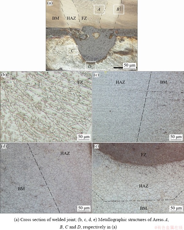
Fig. 2 Morphologies of welded joints
Figure 2 shows the influence of Al-foil addition on the morphology of weld cross section. It is found that some defects, such as pores, cracks and softening in heat affected zone (HAZ), can be avoided in welding joint based on adjusting welding parameters. In Fig. 2(a), the steel side is divided into fusion zone (FZ), heat affected zone (HAZ) and base metal (BM) from the center of the weld to the edge. There are no gas holes and cracks in the welded joint. Metals in the fusion zone undergo the processes of metal melting, crystal nucleation and grain growth. Further analysis for crystal morphology is presented in Figs. 2(b)-(e) from Regions A, B, C and D of Fig. 2(a). Based on Fig. 2(b), it is found that the microstructure in the fusion zone is composed of ordered columnar grains. In Fig. 2(c), the base material of DP590 dual-phase steel consists of a ferrite matrix and a diffusely distributed martensite. No pearlite, sorbite, troostite and bainite are found in the heat affected zone, indicating that the dual-phase steel did not soften during the welding process. In Figs. 2(d) and (e), the center-to-edge of the magnesium side weld is also divided into three parts, which are FZ, HAZ and BM. The grain size tends to grow near FZ on the magnesium side.
3.2 Tensile-shear strength
Figure 3 shows the influence of Al-foil addition on fracture interface at steel/magnesium welded joint. It is found that the fracture position of the welded sample is between the magnesium plate and Al-foil (Fig. 3(a)), while that of the welded sample is between the magnesium plate and the steel plate without the inter-layer (Fig. 3(b)). The ratio of maximum load to fracture width under tension test (linear strength) is used to characterize the bonding strength of weldments. The average tensile-shear strength of welded joints without Al-foil is only 33 N/mm. The main reason for the low strength of welded joints is that there are no solid solution and metallurgical reaction between steel and magnesium. The wetting and spreading effect of magnesium on steel is also weak. There are many welding defects in welded joints without Al-foil, such as pore and surface collapse. In the case of adding Al-foil, the average tensile-shear strength of welded joints is 52 N/mm, which means that the bonding strength of steel/magnesium welded joints can be increased by adding Al-foil.
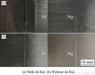
Fig. 3 Fracture interface at steel/magnesium welded joint
3.3 Microstructure and element distribution
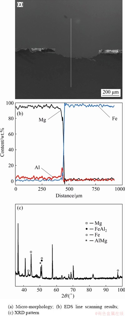
Fig. 4 Micro-morphology and phase composition of steel/magnesium welded joint without inter-layer
Figure 4 shows the micro-morphology and phase composition of the steel/magnesium welded joint without inter-layer obtained at a welding power of 1700 W and a welding speed of 1800 mm/min. It is found in Fig. 4(b) that there is no transition layer at the bonding interface, and the aluminum atom content reaches the peak at the bonding interface, indicating that the aluminum atom tends to diffuse from the welding base metal to the bonding interface. It is found in Fig. 4(c) that the only new phases formed in the joint are FeAl2 and AlMg. The lack of atomic diffusion and metallurgical reaction at the bonding interface results in low joint bonding strength.
Figure 5 shows the morphology of weld cross section and element distribution at the interface with welding powers of 2100 and 2200 W after adding Al-foil. It can be found that the molten pool is divided into upper and lower parts from the interface. There is a clear boundary between the two parts. The upper and lower molten pools are well combined without cracks. As the laser power increases, the melting depth of the magnesium side molten pool increases, but the magnesium plate did not burn, and the surface of the steel plate was not seriously collapsed. As shown in Figs. 5(a) and (b), the magnesium side molten pool is convex toward the steel side molten pool. As the laser power increases, the degree of bulging increases. The linear strength of the joint shown in Fig. 5(b) is only 44 N/mm, and the linear strength of the joint will continue to decrease with the increase of laser input energy. In Area C of Fig. 5(b), the inter-layer was fused and destroyed by excessive laser energy, which seriously impaired the joint performance. Selection of appropriate welding parameters is very important for fusion welding between steel and magnesium dissimilar metals.

Fig. 5 Micro-morphology of welded joints after adding Al-foil and element distribution at interface
EDS mappings of the section in Fig. 5(a) are shown in Figs. 5(c)-(e). It can be found that aluminum and magnesium are evenly distributed in the lower molten pool (Figs. 5(c) and (d)). The bottom of the lower molten pool is well connected with the base metal of the magnesium side. The inter-layer at the joint melts completely and mixes evenly with the molten magnesium in the lower molten pool. In Fig. 5(e), the bottom of the steel is opened downward so that the upper and lower pools can contact and combine with each other. The element mapping of the Area D in Fig. 5(b) is shown in Fig. 5(f), the iron is surrounded by a layer of aluminum in the lower molten pool. There is a thin transition layer between the upper and lower pools. Therefore, the transition layer plays an important role in the connection of the upper and lower molten pools.
In order to understand the types of ICMs formed at the interface, EDS results of the marked points in Fig. 5(a) are shown in Table 3. XRD analysis was conducted to determine phase structure type of weld, as shown in Fig. 6. It can be seen that that Al12Mg17 is formed in the molten pool, while aluminum-magnesium eutectic structure is mainly formed in the lower molten pool. The boundary between the upper and lower molten pools is mainly ICMs formed by iron and aluminum, such as AlFe, FeAl2 and AlFe3. EDS line scanning was carried out on the welded cross section, and the result is shown in Fig. 7. There is a layer of about 87 ��m-thick transition layer between the upper and lower molten pools. It is noted that the Al peaked in the transition layer based on the EDS line scanning results shown in Fig. 7, which indicates that Al diffuses from the inter-layer to the interface and participates in the metallurgical reaction.
Table 3 Elemental compositions at boundary of molten pool (at.%)
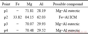
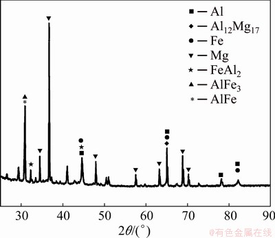
Fig. 6 XRD pattern of joint cross section

Fig. 7 EDS line scanning results about line marked at Fig. 5(a)
3.4 Temperature and flow field simulation
Figure 8 exhibits the influence of Al-foil addition on distribution of temperature field parallel to the welding direction at 0.2 s after the beginning of welding. It is found that when Al-foil is added, the highest temperature on the steel surface is higher than the boiling point of iron, but the region is small, which is due to the excessive concentration of laser energy on the steel surface directly irradiated. The isotherms on the cross section parallel to the welding direction are not symmetrical. The formation of lower molten pool lags behind that of upper molten pool. The temperature at the bottom of the steel side is lower than the melting point of the steel, but the thickness of this layer is very thin. Figure 8(b) shows a temperature field simulation without Al-foil. Under the same welding parameters, the temperature on the magnesium plate has exceeded the boiling point of magnesium without Al-foil. During the welding process, the magnesium plate will be gasified violently, the pores in the welded joint will be formed, and the surface of the weldment will collapse seriously. Therefore, heat transfer between steel and magnesium needs to be regulated, and adding Al-foil can play an important role in regulating the temperature field of steel/magnesium melting welding process.
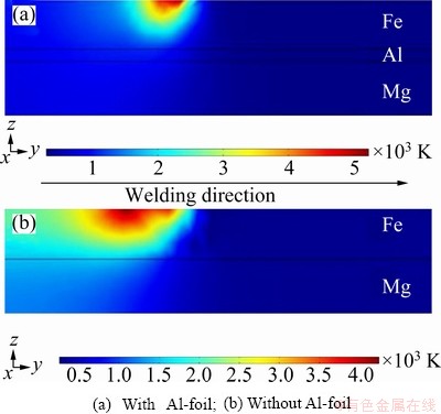
Fig. 8 Distribution of temperature field on weldment at 0.2 s after beginning of welding
The metallographic structure and temperature field distribution on the cross section in the vertical welding direction are shown in Fig. 9. It takes a certain time for laser energy to transfer from the surface of the steel plate to the interior of the workpiece, and the molten pool at the bottom of the workpiece is formed later than that at the top, so the size of the simulated molten pool and the actual molten pool cannot be directly compared. However, the simulation results of the maximum width of the molten pool and the maximum width of the HAZ on the steel side are comparable with the actual size. The simulation results of the maximum width of the molten pool on the steel side are very close to the actual size. The maximum width of the steel-side heat-affected zone in the simulation results is similar to the maximum width of the steel-side heat-affected zone in the actual joint. Therefore, the simulation model is reasonable for the calculation and analysis of temperature field and flow field distribution of steel/magnesium laser welding.
Figure 10 shows the highest temperature versus time curves on aluminum and magnesium plates. It is found that magnesium and aluminum begin to melt after 0.09 and 0.11 s, respectively. The highest temperature on the magnesium plate is always between the melting point and boiling point of the magnesium, therefore, there is enough melting depth on the magnesium plate, and the magnesium plate will not gasify. The maximum temperature of aluminum sheet is always higher than the melting point of aluminum. The highest temperature of aluminum plate exceeds the boiling point of magnesium, therefore, magnesium gasification can be prevented by the aluminum inter-layers during welding.
Figure 11 shows the relationship between the temperature versus time of points on a cross section perpendicular to the welding direction. It can be seen that although the formation of lower molten pool is later than that of upper molten pool, there is a period of time in which the upper and lower molten pools exist simultaneously on the same section, which is beneficial to the contact between the upper and the lower pools during the welding process. The highest temperature reached at P1 on the cross section is 2326 K, located in the molten fusion zone on the steel side. The highest temperature at P2 is 1475 K. The temperatures of P1 and P2 drop very fast, and the resulting metallographic structure contains a large amount of martensite. A good agreement can be seen between the experimental results shown in Fig. 2 and numerical simulations for the metallographic structure of the welded joint. Because the temperatures of molten pool and heat-affected zone decrease faster than that of martensite formation, dual phase steel will not soften during welding.
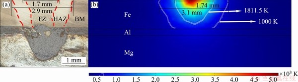
Fig. 9 Metallographic structure (a) and temperature field distribution (b) on cross section in vertical welding direction
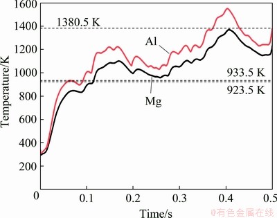
Fig. 10 Temperature versus time curves on aluminum and magnesium plates
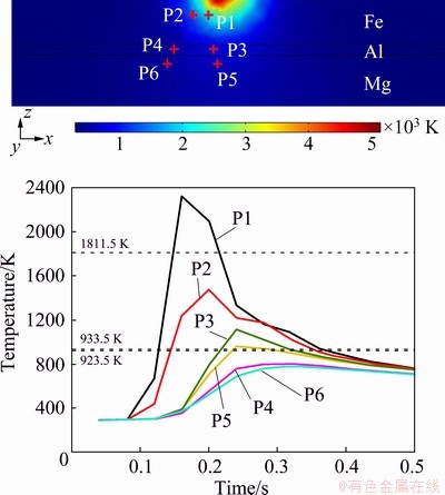
Fig. 11 Relationship between temperature of points on cross section of weldment and time
The maximum temperature at P3 is 1117 K, which is located in the fusion zone of the lower molten pool. When the thin layer of steel between the upper and lower molten pools is opened, molten iron is first contacted with aluminum and then begins to solidify rapidly. The addition of an aluminum inter-layer prevents direct contact between the steel molten pool and the magnesium molten pool. When magnesium diffuses in the lower molten pool until it begins to contact iron, the steel has solidified and the temperature is not enough to vaporize the magnesium. The maximum temperature reached at P5 is 962 K, which means that there is enough heat to melt the magnesium, and the magnesium molten pool and the aluminum molten pool have sufficient conditions to mix. The maximum temperatures of P4 and P6 are only 805 and 780 K, respectively, and the temperature change around the molten pool on magnesium and aluminum plates is relatively small. Hence, the grains of magnesium and aluminum will not grow significantly.
Figure 12 shows distribution of flow field on the cross section parallel to the welding direction. The simulation of liquid metal flow in molten pool is only taken into account the Marangoni effect caused by temperature, the gravity of materials and the effect of dynamic viscosity of materials on the flow field. It was found that the molten metal flows relatively slowly, which ensures the stability of the molten pool. The liquid metal flow in the aluminum side molten pool is the fastest. Because the dynamic viscosity of steel is relatively large, the liquid metal flow in the molten pool on the steel side is slow. In the horizontal direction, the flow direction of the molten metal is opposite to the welding direction. The molten metal flow in the opposite direction to the welding direction is beneficial to replenishing the volume shrinkage due to solidification.
3.5 Mechanism of steel/magnesium melting welding
Based on the results of microstructural analysis and element distribution detection, the mechanism of steel/magnesium laser fusion welding was determined with the help of the schematic diagram shown in Fig. 13, which shows the direction of atom diffusion of various metals, the direction of molten metal flow in the molten pool and the phase formed in the weld. Under direct laser irradiation, dual steel begins to melt first to form the upper side molten pool, and then the heat is transferred to the aluminum and magnesium plates, and the aluminum and magnesium plates begin to melt to form the lower side molten pool. However, according to the simulation results of temperature field in welding process, when there is sufficient penetration on the magnesium plate, the steel plate cannot be completely melted, so an no melting iron wall between the upper and lower molten pools will exist. As the welding process proceeds, this layer of no melting steel will be opened up. When the upper and lower molten pools start to contact, the upper molten pool has begun to solidify due to the higher solidification temperature of the steel. Therefore, although the upper and lower molten pools will contact, they will not mix. In Fig. 13(b), the fracture position is between the lower molten pool and the magnesium base metal.
The flow trend of molten metal in molten pool is shown in Fig. 13(a). The molten metal in the center of the molten pool flows upward, causing the lower molten pool to bulge upward after solidification of molten metal. The aluminum atom and the magnesium atom in the molten pool are mutually diffused, and due to the continuous flow of molten metal in the molten pool, magnesium and aluminum are uniformly mixed in the molten pool. In a homogeneous mixed system of aluminum and magnesium, the magnesium content accounts for about 70 wt.%. When the temperature drops to around 711.5 K, the system begins to undergo eutectic reaction to form L-Mg and ��(Al12Mg17). The aluminum atoms in the molten pool diffuse into the iron, some atoms form ICMS with iron, and some aluminum is enriched around the iron to form a transition layer containing aluminum.
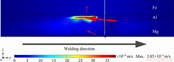
Fig. 12 Distribution of flow field on weldment at 0.3 s after beginning of welding
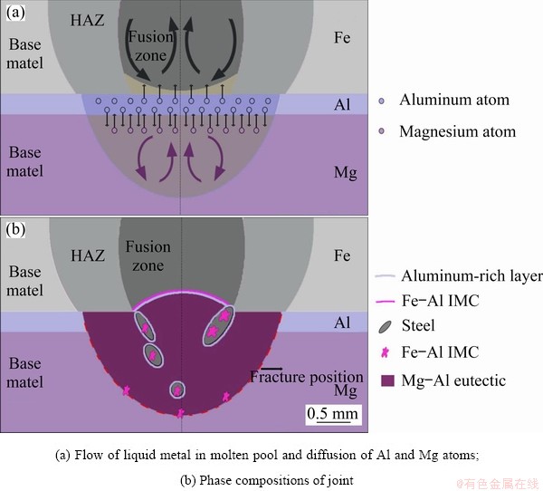
Fig. 13 Schematic of bonding mechanism
4 Conclusions
(1) When Al-foil was added as inter-layer, some defects, such as pores, cracks and softening in heat affected zone (HAZ), can be avoided in welding joint, and the average tensile-shear strength of steel/magnesium joints is increased.
(2) Heat transfer between steel and magnesium and temperature field of the joints are regulated with Al-foil addition, the simultaneous melting of steel and magnesium can be seen, which is favorable for the metallurgical connection of magnesium and steel.
(3) In the case of adding Al-foil, the welding pool is divided into two parts, the upper and lower pools contact each other but do not mix, the transition layer at the interface between the upper and lower molten pools mainly contains Al-Fe phases, such as AlFe, Al2Fe and AlFe3, which is formed by the reaction of iron and aluminum, and these new phases are helpful for promoting the metallurgical connection between the upper and lower molten pools. Hence, adding Al-foil laser fusion welding is an effective way in joining steel to magnesium alloy.
References
[1] LUO A, PEKGULERYUZ M O. Cast magnesium alloys for elevated temperature applications [J]. Journal of Materials Science, 1994, 29(20): 5259-5271.
[2] DAI J, HUANG J, LI Z G, DONG J, WU Y X. Effects of heat input on microstructure and mechanical properties of laser-welded Mg-rare earth alloy [J]. Journal of Materials Engineering and Performance, 2013, 22(1): 64-70.
[3] YANG X W, FENG W Y, LI W Y, DONG X R, XU Y X, CHU Q, YAO S T. Microstructure and properties of probeless friction stir spot welding of AZ31 magnesium alloy joints [J]. Transactions of Nonferrous Metals Society of China, 2019, 29(11): 2300-2309.
[4] TAN C W, XIAO L Y, LIU F Y, CHEN B, SONG X G, LI L Q, FENG J C. Influence of laser power on the microstructure and mechanical properties of a laser welded-brazed Mg alloy/Ni-coated steel dissimilar joint [J]. Journal of Materials Engineering and Performance, 2017, 26(6): 1-15.
[5] LI L Q, TAN C W, CHEN Y B, GUO W, HU X B. Influence of Zn coating on interfacial reactions and mechanical properties during laser welding-brazing of Mg to steel [J]. Metallurgical & Materials Transactions A, 2012, 43(12): 4740-4754.
[6] SONG G, AN G Y, LIU L M. Effect of gradient thermal distribution on butt joining of magnesium alloy to steel with Cu-Zn alloy interlayer by hybrid laser�Ctungsten inert gas welding [J]. Materials & Design, 2012, 35: 323-329.
[7] SONG G, LI T T, ZHANG Z D, LIU L M. Investigation of unequal thickness Mg/steel butt-welded plate by hybrid laser-tungsten inert gas welding with a Ni interlayer [J]. Journal of Manufacturing Processes, 2017, 30: 299-302.
[8] LIU L M, QI X D, ZHANG Z D. The effect of alloying elements on the shear strength of the lap joint of AZ31B magnesium alloy to Q235 steel by hybrid laser-TIG welding technique [J]. Metallurgical & Materials Transactions A, 2012, 43(6): 1976-1988.
[9] LIU L M, QI X D, WU Z H. Microstructural characteristics of lap joint between magnesium alloy and mild steel with and without the addition of Sn element [J]. Materials Letters, 2010, 64(1): 89-92.
[10] SONG G, LI T T, CHEN L. The mechanical properties and interface bonding mechanism of immiscible Mg/steel by laser�Ctungsten inert gas welding with filler wire [J]. Materials Science and Engineering A, 2018, 736: 306-315.
[11] SHEN J, WANG L Z, ZHAO M L, WANG D, XU N. Effects of activating fluxes on pulsed laser beam welded AZ31 magnesium alloy [J]. Science and Technology of Welding and Joining, 2012, 17(8): 665-671.
[12] WINDMANN M, ROTTGER A, K��GLER H, THEISEN W. Laser beam welding of magnesium to coated high-strength steel 22MnB5 [J]. International Journal of Advanced Manufacturing Technology, 2016, 87(9-12): 3149-3156.
[13] CASALINO G, GUGLIELMI P, LORUSSO V D, MORTELLO M, PEYRE P, SORGENTE D. Laser offset welding of AZ31B magnesium alloy to 316 stainless steel [J]. Journal of Materials Processing Technology, 2017, 242: 49-59.
[14] CHEN Y C, NAKATA K. Effect of tool geometry on microstructure and mechanical properties of friction stir lap welded magnesium alloy and steel [J]. Materials & Design, 2009, 30(9): 3913-3919.
[15] WANG T H, SHUKLA S, GWALANI B, KOMARASAMY M, REZANIETO L, MISHRA R S. Effect of reactive alloy elements on friction stir welded butt joints of metallurgically immiscible magnesium alloys and steel [J]. Journal of Manufacturing Processes, 2019, 39: 138-145.
[16] WATANABE T, YANAGISAWA A, KONU MA S, DOI Y. Resistance spot welding of mild steel to Al-Mg alloy [J]. Welding International, 2005, 23(4): 290-294.
[17] LIU L, XIAO L, FENG J C, TIAN Y H, ZHOU S Q, ZHOU Y. The mechanisms of resistance spot welding of magnesium to steel [J]. Metallurgical & Materials Transactions A, 2010, 41(10): 2651-2661.
[18] REN D, ZHAO K, PAN M, CHANG Y, GANG S, ZHAO D. Ultrasonic spot welding of magnesium alloy to titanium alloy [J]. Scripta Materialia, 2017, 126: 58-62.
[19] ZHOU D W, LI T, XU S H, LIU J S. Numerical and experimental investigations in laser welding for steel and magnesium alloy [J]. Lasers in Manufacturing and Materials Processing, 2018, 5(3): 222-236.
����������DP590˫���/AZ31Bþ�Ͻ��ۻ�����ͷ����֯���¶ȳ���Ӱ��
�� ��1,2������ˮ1,2���ܵ���2���� �1,2
1. ���ϴ�ѧ ���Ͽ�ѧ�빤��ѧԺ����ɳ 410082��
2. ���ϴ�ѧ ���������Ƚ������������ص�ʵ���ң���ɳ 410082
ժ Ҫ����DP590˫��ֺ�AZ31Bþ�Ͻ���и���/þ�´�Ӻ�/þ������������ļ����ۻ������飬����COMSOL����Ԫ�����Ը�/þ�ۻ����¶ȳ�������ֵģ�⡣�������������������ʵ�ָ�/þ��Ч���ӣ����������ס����ƺ���Ӱ����������ȱ�ݣ���ͷ���ǿ����ߣ����������ɵ��ظ�/þ����������ݣ���/þ�۳ط��ϡ��������֣�����Ӵ�����������ϣ�����Ϊ��������Ӧ���ɵ�AlFe��Al2Fe��AlFe3��������ɵĹ��ɲ㣬�ٽ��ϡ����۳�ұ���ϡ���ˣ��������������ۻ�����ʵ�ָ�/þ���ֽ������ӵ���Ч������
�ؼ��ʣ����ֽ������ӣ�����֯����ֵģ�⣻����
(Edited by Xiang-qun LI)
Foundation item: Projects (51774125, 51674112) supported by the National Natural Science Foundation of China; Project (2018YFB1107905) supported by the National Key Research and Development Program of China
Corresponding author: Dian-wu ZHOU, Tel: +86-13017297124, Fax: +86-731-88821483, E-mail: ZDWe_mail@126.com;
Jin-shui LIU, Tel: +86-13808478038; E-mail: Jsliu@hnu.edu.cn
DOI: 10.1016/S1003-6326(20)65411-5
Abstract: The experiments of laser fusion welding with Al-foil addition was carried out for DP590 dual-phase steel and AZ31B magnesium alloy in an overlap steel-on-magnesium configuration. Temperature field was simulated by COMSOL finite element software for steel/magnesium laser fusion welding. The results show that when Al-foil is added, some defects, such as pores, cracks and softening in heat affected zone (HAZ), can be avoided in welding joint, the bonding strength of steel/magnesium joints is increased, heat transfer between steel and magnesium is regulated. In the case of adding Al-foil, welding pool is divided into two parts, the upper and lower pools contact each other but do not mix, the transition layer at the interface between the upper and lower molten pools mainly contains Al-Fe phases, such as AlFe, Al2Fe and AlFe3, and these new phases are helpful for promoting the metallurgical connection between the upper and lower molten pools. Hence, adding Al-foil laser fusion welding is an effective way in joining steel to magnesium alloy.
