
J. Cent. South Univ. (2017) 24: 2180-2197
DOI: https://doi.org/10.1007/s11771-017-3627-1

Performance-based passive control analysis of adjacent structures:Optimization of Maxwell dampers
WU Qiao-yun(������)1, 2, DAI Jian-zhou(������)1, ZHU Hong-ping(���ƽ)2
1. School of Resource and Civil Engineering, Wuhan Institute of Technology, Wuhan 430073, China;
2. School of Civil Engineering and Mechanics, Huazhong University of Science and Technology,Wuhan 430074, China
 Central South University Press and Springer-Verlag GmbH Germany 2017
Abstract:
The performance-based passive control analysis of the Maxwell dampers between one 10-story and one 6-story adjacent RC frames is conducted in this work. Not only the optimal parameters but also the optimal arrangements of the Maxwell dampers are proposed based on the optimal target of making the total exceeding probability of the adjacent structures to be minimal. The applicability of the analytical expressions of the Maxwell damper damping parameters under different seismic performance targets are firstly examined and then the preferable damping parameters of the Maxwell dampers are proposed through the extensive parametric studies. Furthermore, the optimal arranging positions and optimal arranging numbers of the Maxwell dampers between the adjacent buildings are derived based on a large number of seismic fragility analyses, as well. The general arranging laws of the Maxwell dampers between the adjacent buildings are generated based on the discussion of the theoretical method through the simplified plane model. The optimal parameters and optimal arrangement of the Maxwell dampers presented make both the adjacent structures have preferable controlled effects under each seismic performance target which can satisfy the requirements of multi-performance seismic resistance of the modern seismic codes.
Key words:
1 Introduction
With the increasing development of urbanization, there has been a large number of smaller spacing adjacent buildings. Because of the insufficient separations, collision can occur between such buildings during strong ground motions. Pounding may result in local damage to columns, collapse of damaged floors and collapse of entire structures. Many scholars have suggested to install the control devices between the adjacent buildings, using the relative vibration to absorb the seismic energy of buildings connected to each other.
Passive connection control has received significant attention because of its reliability and inherent stability. The large body of work in passive connection control is based on determining the optimal parameters of passive connection elements. ZHU et al [1] proposed a control method to reduce the seismic response using the interaction between master-slave structures. They derived the general expressions of the optimal stiffness and damping of the passive dissipated devices under the stationary white noise excitation. They also analyzed the influence of the structural parameters on the control effects. Afterwards, ZHU et al [2] simplified the adjacent structures into two single-degree of freedom (SDOF) systems, and used Viogt viscoelastic damping model to represent the passive connection unit to derive the general expressions of optimal stiffness and damping of the control devices which were suffered from the random ground excitation using Kuhn-Tucker optimization principle. Since then, ZHU et al [3-7] proposed the analytical expressions of the optimum parameters of Kelvin and Maxwell dampers between catamaran SDOF systems based on the principle of energy statistics. XU et al [8] obtained a closed-form solution of seismic response for adjacent structures which were interconnected by LQG controller. Through this closed- form solution, parametric study of the structures between the adjacent multi-degree of freedom (MDOF) systems were performed, and the favorable parameters which can control and reduce the maximum response of the adjacent structures were found. BHASKARARAO et al [9, 10] studied the control effect of the friction dampers which were used to interconnect the adjacent buildings. The results showed that the friction dampers can get a good energy dissipation effects. BHASKARARAO et al [11] simulated the base acceleration as a harmonic vibration and smooth Gaussian white noise excitation, and studied the seismic response of two adjacent single- degree of freedom systems which were interconnected by viscous dampers. They derived the structural motion equations and obtained the relative displacement and absolute acceleration response of the adjacent structures. The results showed that when the viscous dampers had appropriate damping they can reduce the seismic response between the adjacent structures. BASILI et al [12, 13] analyzed the control effects of the nonlinear hysteretic controller which was used to interconnect adjacent buildings. By simplifying the adjacent structures into single-degree of freedom systems, they got the optimum parameters of the hysteretic controllers prone to the Gaussian white noise and filtered white noise excitation using equivalent linearization method. OKet al [14] performed the optimized control study on adjacent structures which were interconnected by the hysteretic dampers based on multi-objective optimization and stochastic equivalent linearization method. Through a large number of nonlinear random vibration analyses, they studied the robustness of the optimized design by considering seismic randomness. RICHARDSON et al [15] developed closed-form equations for the optimal stiffness and damping of passive connection element between adjacent vibrating structures and demonstrated the application of equations for MDOF-connected structures subject to earthquake ground motions. PATEL et al [16] derived the dynamic response of adjacent two- degree-of-freedom structures connected with viscous dampers and ascertained the optimum value of damping coefficient of damper and derived the close-form expression for optimum damping coefficient of damper and corresponding responses of the structure. TUBALDI [17] expressed the equation of motion of the system undergoing damped free vibration in nondimensional form in order to identify the minimal set of characteristic parameters controlling the dynamic behavior. The analytical relationship between these parameters and the dynamic properties of coupled structures were obtained by solving the relevant complex eigenvalue problem. Successively, the equation of motion was expressed in weak form, and a reduced-order model of the system was built based on the assumed modes method to derive simplified formula for estimating the damping ratio of the first two modes of the coupled structures and, thus, to obtain useful information regarding the optimal damper properties.
The control effects of the Maxwell dampers depend not only on the optimal parameters but also on the optimal arrangements. So far the previously mentioned analysis mainly focused on the optimal parameters and ignored the optimal arrangement of the dampers. Moreover, the optimal parameters were always proposed under the elastic state of the seismic response which did not consider the non-linear behavior of the adjacent structures. The applicability of the optimal parameters under different performance targets, especially under life safety (LS) or collapse prevention (CP) limit states when the adjacent structures subjected to strong ground motions, should be further examined. In order to get preferable controlled effects of the adjacent structures, the performance-based control analysis is incorporated in this work according to the suggestions of some modern seismic codes [18, 19].
The performance-based passive control analysis of the Maxwell dampers between one 10-story and one 6-story adjacent RC frames is conducted in this work. This pair of buildings is subjected to 20 strong ground motions which are absolutely compatible with the design process. Comprehensive analysis of the created response databank is employed to derive significant conclusions. Making the total exceeding probability of the two adjacent structures to be minimal is chosen as the optimal target. The applicability of the analytical expressions of the Maxwell damper damping parameters [6] under different seismic performance targets is firstly examined and then the optimal parameters of the Maxwell dampers are proposed through the extensive parametric studies. Finally, based on two-step optimal design, the optimal arranging positions and optimal numbers of the Maxwell dampers are derived. The optimal parameters and the optimal arrangements of the Maxwell dampers presented make both the adjacent structures have preferable controlled effects under each seismic performance target. The general arranging laws of the optimal arrangement of the Maxwell dampers between the adjacent buildings are generated by the discussion of theoretical method and may have useful instructions for the application of practical engineering.
2 Calculation models
2.1 Calculation models and fundamental assumptions
The simplified models of the adjacent structures interconnected by dampers at some stories are displayed in Fig. 1. The stories are n1 and n2 (n1��n2), respectively.
The following assumptions are incorporated to the calculation models of the adjacent buildings which are interconnected by the passive control devices: 1) The two buildings are plane symmetry. Ignoring the torsion effect, only the seismic action along the horizontal symmetrical surface of the structure is considered. 2) The story height of each building is consistent. The adjacent buildings are interconnected by dampers at the same levels. 3) As the separation distance of the two buildings is very small, the seismic input is assumed to be the same which neglected the spatial variation of the seismic waves. 4) The connected dampers are the viscous fluid dampers which are extensively applied in the actual engineering, and the damper parameters at each story are the same. 5) Pounding between the adjacent buildings is ignored as the connection of the control devices.
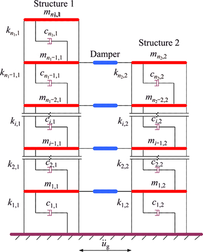
Fig. 1 Calculation models of adjacent buildings interconnected by dampers
2.2 Equation motion of adjacent multi-degree of freedom structures
The shear type model is adopted for the adjacent multi-degree of freedom structures. Structure 1 and Structure 2 are simulated with n1 and n2 lumped mass unites (n1��n2), respectively. The structural system equation can be expressed as:
 (1)
(1)
where M, K and C are the mass, stiffness and damping matrix of the adjacent structures, respectively. The dimensions are all n��n (n=n1+n2); X,  and
and  are the n-dimensional relative displacement, velocity and acceleration vectors, respectively; fi is the output force of the ith damper; di is the indictor vector of the ith damper; nd is the number of the dampers; I is the unit column vector; and
  is the ground acceleration.
The mass matrix of the adjacent structures is expressed as follows:
 (2)
(2)
where , and
, and .
.
The stiffness matrix of the adjacent structures is expressed as follows:
 (3)
(3)
where ,and
,and .
.
The damping matrix of the adjacent structures is expressed as follows:
 (4)
(4)
where ,
, ,
,
Mi, Ki and Ci are the mass, stiffness and damping matrix of Structure i (i=1 to 2), respectively.
2.3 Theoretical expressions of optimal parameters for Maxwell dampers
2.3.1 A generalized single degree of freedom system
In practical engineering applications, the generalized single degree of freedom (SDOF) model is usually adopted to characterize the dynamic response of Structures 1 or 2 under earthquakes, based on the principle of virtual work. The equation motion can be expressed as follows:
 (5)
(5)
where i=1 to 2; 


 ��i is the first vibration mode of Structure i; Mi, Ki and Ci are the mass, damping and stiffness matrices of Structure i, respectively; Li is the generalized equivalent load factor.
2.3.2 Optimal parameters of Maxwell dampers
As shown in Fig. 2, the connected viscous fluid dampers (VFD) are represented by the Maxwell model. The equations of the motion for the two adjacent SDOF structures with Maxwell model-defined fluid dampers can be written as
 (6)
(6)
where 

 (i=1 to 2), and
  and
and  are the generalized mass and stiffness of Structure i, respectively; mi and ��i are the total mass and the first modal damping ratio of structure i, respectively (i=1 to 2), f��(t) is the output force of Maxwell damper at time t; �� is the relaxation time of Maxwell damper, and ��=c0/k.
According to ZHU et al [6], they derived the explicit expressions of the optimal parameters of VFD between 2-SDOF adjacent structures. For different optimization objectives, the formulas of optimal parameters for fluid dampers in ZHU et al [6] are summarized as follows:1) Optimization criterion 1: minimizing the time averaged energy of Structure 1.
When �¡�1,
 (7)
(7)
When ��>1,
 (8)
(8)
The optimal values of the relaxation time and damping coefficient at zero frequency are given, respectively, as:
 (9)
(9)
2) Optimization criterion 2: minimizing the time averaged energy of the two structures.
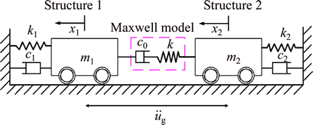
Fig. 2 Two SDOF structures linked by Maxwell model-defined VFD
Likewise, the frequency ratio is restricted to �¡�1. The expressions also can be applied to the case of ��>1 only requiring reciprocal exchange of the two structures. Correspondingly, the optimal damping ratio at zero frequency and optimal non-dimensional relaxation time [6] connecting Maxwell model defined damper can be expressed as follows:
When �̡�1,
 (10)
(10)
When ��<1 and ��2<��(2��-1)/(2-��),
 (11)
(11)
When ��<1 and ��2�ݦ�(2��-1)/(2-��),
 (12)
(12)
Generally, unless there are special requirements on Structure 1, optimization criterion 2 is always used to do passive control analysis of Maxwell dampers as its purpose is to control the overall seismic response of both the adjacent structures. Therefore, in the following analysis which means to examine the applicability of the analytical expressions of the Maxwell dampers, optimization criterion 2 is employed to do performance- based seismic vibration control analysis and examine the control effects of the previously proposed optimized parameters under different performance targets.
3 Description of structures and optimum problems
3.1 Description of structures
The established models are administration buildings located in Xi��an city. The models are adjacent buildings, while Structure 1 is a 10-story reinforced concrete frame structure, and Structure 2 is a 6-story reinforced concrete frame structure. The structural arrangement is regular and symmetric. So to simplify the calculation, one specimen of the models for each structure is selected to establish planar model.
The floor-to-floor height of the two adjacent buildings is equal to 3.6 m. The total height of the 10-story buildings is 36 m, and all their beams and columns are 300 mm��800 mm and 750 mm��750 mm, respectively. The 6-story frames are 21.6 m tall, and all their beams and columns are 300 mm��800 mm and 800 mm��800 mm, respectively. The slab thickness is 100 mm for all the frames.
The longitudinal reinforcement is HRB335 and the stirrup is HPB300. The concrete strength class of beams, columns and plates is C35.
The frames are designed to 8-degree fortification, site classification II, seismic design group 2 with peak ground acceleration (PGA) Apg=0.2 g according to the Chinese Code of GB50011-2010 [19]. The basic wind pressure is 350 Pa and the basic snow pressure is 250 Pa. The dead and live loads (G and Q) are directly applied to the beams. The assumed loading combinations are as follows (Chinese code of GB50009-2012 [20]):
 (13)
(13)
where SPL representing the combination controlled by permanent load effects and SVL representing the combination controlled by variable load effects; the combination coefficient of live load ��c and ��ci are taken equal to 0.7, Q1 is the first live load which has control action and Qi is the ith live load (i��2).
The examined frames have been designed to Chinese codes of GB50010�C2010 [21] and GB50011�C 2010 [19]. The reinforcement design of the frames follows the concept of week beams-strong columns of GB50011-2010 [19] as described by:
 (14a)
(14a)
 (14b)
(14b)
where  is the sum of the resistance moments of the upper and lower ends of the columns at every beam-column joint.
  is the greater value of the
sum of the resistance moments of the left and right ends of the beams at every beam-column joint which are calculated by using the effective reinforcement and characteristic value for the strength of the materials and considering the seismic bearing capacity adjustment factor. Structure 1 is the frames of the first seismic fortification grade which obeys Eq. (14a) and Structure 2 is the frames of the second seismic fortification grade which obeys Eq. (14b).
The frames are considered to be fixed on the ground. Pounding between the adjacent buildings is ignored as the connection of the control devices.
The calculation models of the adjacent structures are shown in Fig. 3. Figure 3 also displays the section numbers and the longitudinal reinforcement of the bottom floor columns.
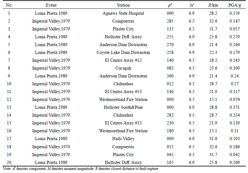
OpenSees [22] program is used to establish the planar models of the adjacent structures to do incremental dynamic analysis, accounting for the material non-linearity. A suite of 20 far-field ground motions, which are selected from PEER Strong Motion Database [23] as an input to IDAs, have been recorded on soil condition II, and therefore, they are compatible with the design process used for the considered frames. The complete list of these earthquakes appears in Table 1. Figure 4 presents the response spectra and the mean spectrum of the examined earthquakes.
The uniaxial Material Maxwell is selected to simulate the Maxwell damper. Beams, columns and Maxwell dampers are simulated by nonlinear fiber beam-column units which are based on displacement. The first natural frequency of Structure 1 is approximately ��1=8.418 rad/s. The first natural frequency of Structure 2 is approximately ��1=17.5254 rad/s. The total mass of Structure 1 and Structure 2 are 303.0705 t and 203.8021 t, respectively.
Maxwell dampers are firstly assigned to each story of the adjacent buildings, totally 6 dampers (equal to the number of stories of the shorter building). Here, the optimization objective is chosen as minimizing the total vibration energy of the tow structures. Using the explicit expressions of Maxwell-model defined VFD between 2-SDOF systems [6], the total optimal relaxation time is
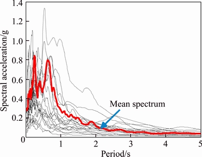
Fig. 4 Response spectra of examined records
calculated to be 0.0408 s, and the total optimal damping coefficient is calculated to be 1.4478��106 N��s/m (each damper damping is 2.413��105 N��s/m) by equations from Eq. (1) to Eq. (9) using MATLAB program.
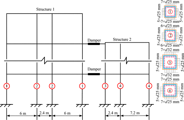
Fig. 3 Calculation model of adjacent structures
Table 1 Earthquake records adopted for IDA
3.2 Determination of performance targets of structures
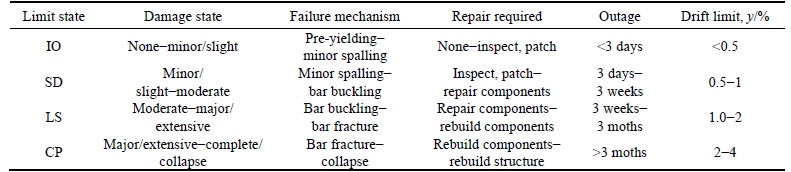
As the best known and most widely used indexes, the maximum story drift is selected as the engineering demand parameters (EDPs, Ped) which can characterize the overall damage index of the structure, and PGA is selected as the seismic intensity measure (IM) in this work. The limit states of the structures are divided into immediately occupation (IO), slightly damage (SD), life safety (LS) and collapse prevention (CP). Each state corresponding to the maximum performance target of y is detailedly listed in Table 2 [24].
3.3 Description of optimum problems
The control objective is to reduce the overall seismic response of the two adjacent structures as much as possible. The total exceeding probability of the two structures is taken as the objective function which is evaluated by P. The optimum problems of the Maxwell dampers including the optimization of parameters and arrangements are expressed as follows:

 (15)
(15)

 (16)
(16)
where  (i=1, 2) is the probability of Structure i where the engineering demand parameter (EDP) exceeds the performance target of y at an given seismic intensity level IM=im.
Incremental dynamic analyses (IDA) are carried out on the adjacent structures under each arranging combination of the Maxwell dampers. The corresponding IDA curves can be derived. Using the MATLAB program to do the post-processing programming on the IDA curves, the logarithmic mean value and variance of the engineering demand parameter (Ped,i (i=1, 2)) for each structure under each seismic intensity measure (IM=im) can be calculated which are denoted as  and
and  respectively. The total exceeding probability of the adjacent structures under each damper arrangement can be calculated by Eq. (15) and Eq. (16). Actually, the structural exceeding probability is usually called the seismic fragility of the structure.
Intensive parametric studies have been employed to derive the optimal parameters of the Maxwell dampers which can export preferable control effects on both the adjacent structures under each performance target (y). In this section, totally 180 examined IDA have been investigated: (20 strong seismic ground motions)��(9 different parameters).
The research of the optimal arrangement of the Maxwell dampers between the adjacent buildings needs two steps: the first step is the optimization of the arranging positions, and the second step is the optimization of the arranging numbers.
In the first step, the arranging number of the Maxwell dampers between the adjacent buildings is determined as a certain value which is denoted as n, and n=1 to m, where m is the number of the stories of the shorter building of the adjacent buildings, here m=6. In each case (for n=1 to m), there are  different combinations of arranging positions. In this section, totally 1260 examined IDAs have been investigated:(20 strong seismic ground motions)��
 different arranging combinations). Then, the probability of the exceedance for each damper arrangement of the adjacent structures can be calculated based on Eq. (16). By comparing the total exceeding probability of the two adjacent structures under all kinds of combinations of the arranging positions, the arrangement corresponding to the minimal exceeding probability is the optimal arranging positions of the Maxwell dampers when the arranging number is n. The method of exhaustion is adopted to find the optimal arranging positions of the Maxwell dampers between the adjacent buildings, therefore, all combinations of the damper arrangement are taken into consideration in this step.
Table 2 Performance targets (y) of each limit state
In the second step, the total exceeding probabilities of the adjacent structures under each performance target, when interconnected by Maxwell dampers with different numbers and optimal arranging positions, are compared. The corresponding number of the Maxwell dampers for the adjacent structures with the minimal exceeding probability is the optimal number. Through these two steps, the arranging positions and arranging numbers of the Maxwell dampers under each performance target are optimized which can get the general rules of the control effects of the Maxwell dampers changing with the variation of arrangements.
4 Results
4.1 Examination of analytical expressions of Maxwell damping parameters
Using the damping parameters which are calculated by the analytical expressions proposed by ZHU et al [6] in section 3.1, the applicability of the optimized expressions of the Maxwell dampers under each performance target is examined. The performance-based passive control analysis is carried out. Based on the IDA curves of the adjacent structures, after-treatment programming is conducted using MATLAB. In this section, the optimal arrangements of the Maxwell dampers are ignored, the dampers are fixed in each story of the adjacent buildings. The total number of the dampers is six which is equal to the number of stories of the shorter building between the adjacent buildings. The settings of the Maxwell dampers for each story are the same.
Figure 5 depicts the seismic fragility curves of the adjacent structures under each performance target with and without control.
It is noted that the Maxwell dampers have no control effects for all kinds of performance targets and even enlarge structural response under some performance targets (such as SD and LS) on Structure 1.
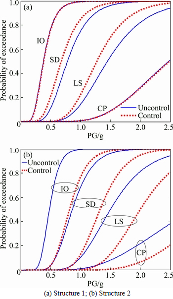
Fig. 5 Seismic fragility curves of adjacent structures with calculated damping parameters:
On the other hand, the Structure 2 has relatively well controlled effects under each performance targets in comparison with Structure 1. Figure 5 shows that the applicability of the Maxwell dampers�� optimized parameters which calculated by ZHU et al [6], especially for Structure 1, is questionable. To explain this phenomenon, one should take into account that the analytical expressions of the damping parameters [6] were calculated based on the assumption of linear elasticity and ignored the inelastic behavior of the neighbouring members when suffered from strong ground motions.
Therefore, the better optimization of the Maxwell dampers�� parameters appears to be indispensable to have preferable control effects on both adjacent structures under each performance target. In the future work, a quantitative of parametric analyses are carried out based on the principle of minimizing the seismic fragility of the two adjacent structures to find the optimal parameters of the Maxwell dampers.
4.2 Optimization of damping parameters
In order to explore more appropriate damping parameters of the Maxwell dampers at each performance targets between the adjacent structures, in this work, a large number of incremental dynamic analyses under different damping parameters are performed. Based on the incremental dynamic analyses, the seismic fragility curves of the adjacent structures under each damping parameter are derived. Because of the less impact of the stiffness coefficient of the Maxwell dampers on the control effectiveness, the seismic fragility of the adjacent structures is only studied under different damping parameters, and based on the principle of minimizing the seismic fragility, the appropriate damping parameters are proposed.
Figures 6 and 7 depict the seismic fragility curves of the adjacent structures under nine different damping parameters when suffered from the 20 strong ground motions: 1.0��104, 1.0��105, 1.5��105, 2.0��105, 2.4��105 (the calculated damping parameter by Ref. [6]), 3.0��105, 1.0��106, 1.0��107 and 1.0��108 N��s/m. According to the commonly used type selection of the viscous fluid dampers (Maxwell model), the value range of the damping coefficient is generally from 1.0��104 N��s/m to 5.0��106 N��s/m, therefore, the damping parameters evaluated in this work can cover this range. Moreover, it takes more values in the vicinity of the calculated damping parameter which can be refereed as the basis reference.
Figure 6 shows that when Structure 1 undergoing the three stages of immediately occupation (IO), slightly damage (SD) and life safety (LS), if the damper damping parameter is set to 1.0��104 N��s/m, the probability of exceedance is minimal. Then, when Structure 1 experiences collapse prevention (CP) stage, even increasing the damping parameter to 1.0��106 N��s/m, the probability of exceedance is very close to the probability whose damping coefficient is 1.0��104 N��s/m or 1.5��105 N��s/m, and when the damping is set to 2.4��105 N��s/m according to Ref. [6], the probability is actually maximum. While, the probabilities of exceedance with the damping parameter of 2.4��105 N��s/m are all relatively large under other three performance targets, which proves once again that the optimal parameters of the Maxwell dampers calculated by the analytical expressions are not applicable to Structure 1.
For Structure 2, when it experiences the seismic performance targets of IO, SD and LS, if the damper damping parameter is set to 1.5��105 N��s/m, the probability of exceedance of the structure is basically minimal. Then, when Structure 2 experiences collapse prevention (CP) stage, when the damping coefficient is set to 2.4��105 N��s/m according to ZHU et al [6], the probability of exceedance is minimal. The exceeding probability is minor as well when setting the damping parameter to 1.5��105 N��s/m. Generally speaking, the optimal damping parameter can be selected as 1.5��105 N��s/m for Structure 2 as it has well control effects under each performance target.
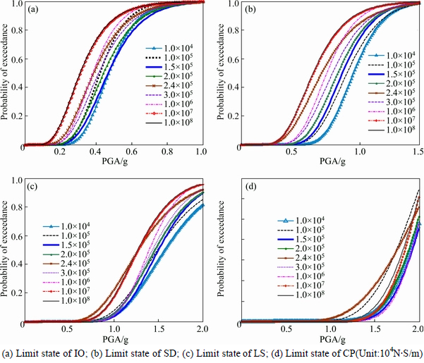
Fig. 6 Fragility curves of Structure 1 under different damping parameters:
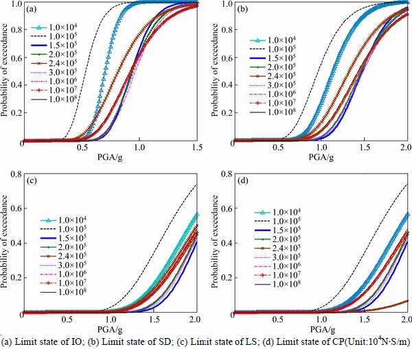
Fig. 7 Fragility curves of Structure 2 under different damping parameters:
From the above analysis, it can be found that the adjacent structures have different optimal damping parameters under different performance targets. The damping parameters which have significant control effects to Structure 1 may have badly control effects to Structure 2. In order to find the more appropriate damping optimization parameters which can simultaneously control the probability of exceedance of the two structures under each performance target, based on the optimal target of making the total exceeding probability of the two structures minimum, the optimal damping parameter values are derived. Figure 8 shows the total exceeding probability of the two structures under different performance targets.
Figure 8 shows that, under the performance targets of IO, SD and LS, when the damping parameter of Maxwell dampers is set to 1.5��105 N��s/m, both the adjacent structures have the minimum exceeding probability. Even under CP performance target, although the optimized damping parameter is 2.4��105 N��s/m, when the parameter is set to 1.5��105 N��s/m the exceeding probability of the adjacent structures is also very low.
In order to more intuitively get the optimal parameters of the Maxwell dampers, Fig. 9 plots the mean total exceeding probability of the two structures under different performance targets.
Figure 9 displays that, when the damping parameter of the Maxwell dampers is set to 1.5��105 N��s/m, the mean total exceeding probability of the two structures under IO, SD and LS performance targets can be relatively minimal. Additionally, the optimal damping parameter is 2.413��105 N��s/m under CP performance target (calculated by Ref. [6]). However, the parameter of 1.5��105 N��s/m is another appropriate advice. In all, it chooses 1.5��105 N��s/m as the optimized damping parameter in this work. Furthermore, Fig. 8 also presents that when the damping parameter is set to 1.0��105 N��s/m the control effect is the worst for all seismic performance targets. From the change of the trend in the graph, the minimum points can be derived which proves the reasonableness of the data range of the damping parameters evaluated by this work.
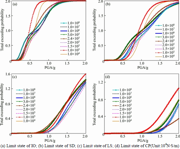
Fig. 8 Total exceeding probability of adjacent structures under different damping parameters:
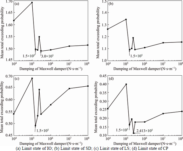
Fig. 9 Mean total exceedance of probability of adjacent structures under different damping parameters:
4.3 Optimization of arrangement
As stated earlier, the optimized parameters of the Maxwell dampers between the adjacent buildings have been studied. However, the control effects of the Maxwell dampers depend not only on the optimization of the output force of the dampers, but also on the arrangement of the dampers in the structures. The optimized arrangement of the Maxwell dampers involves two variables of arranging positions and numbers.
4.3.1 Optimization of arranging positions
Incremental dynamic analyses and seismic fragility analyses are carried out on the adjacent structures which interconnected by Maxwell dampers with  different arranging combinations. Based on the optimal target of Eqs. (15) and (16), the total exceeding probabilities of the adjacent structures under each arranging combination are calculated by programming with MATLAB.
Figures 10-14 show the total exceeding probabilities of the adjacent structures under different performance targets with different arrangements of the Maxwell dampers.
Figure 10 describes the total exceeding probability of the two adjacent structures under different performance targets when interconnected by one Maxwell damper. The arrangement of the Maxwell damper has 6  situations. The legend ��1�� means the Maxwell damper is located at the first floor. The legend ��2�� means the Maxwell damper is located at the second floor, others and so on.
Figure 10 reveals that, when PGA is small, the arranging position of the Maxwell damper has no influence on the structural seismic fragility. With increasing PGA, the optimal position is the sixth floor (legend ��6��), and when setting the Maxwell damper in the sixth floor (legend ��6��), the adjacent structures can get the minimal total exceeding probability for all kinds of performance targets. Figure 10 also presents that the first floor (legend ��1��) of the adjacent buildings is the worst position when arranging one damper between the adjacent buildings.
Figure 11 shows the total exceeding probability of the two adjacent structures under different performance targets when connected by two Maxwell dampers. The arrangement of the Maxwell damper has 15  situations. The legend ��1, 2�� means the two Maxwell dampers are respectively located at the first and second floor. The legend ��1, 3�� means the two Maxwell dampers are respectively located at the first and third floor, others and so on.
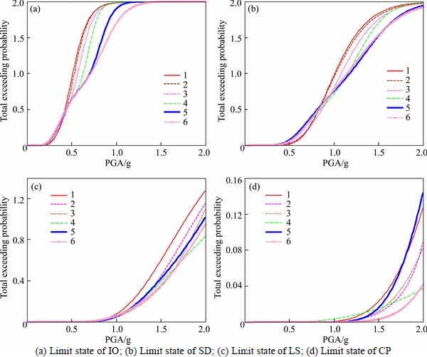
Fig. 10 Total exceeding probability of adjacent structures interconnected by one damper:
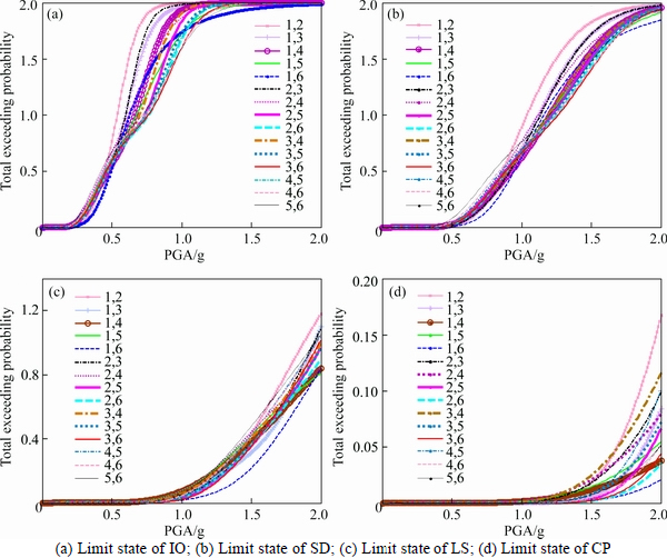
Fig. 11 Total exceeding probability of adjacent structures interconnected by two dampers:
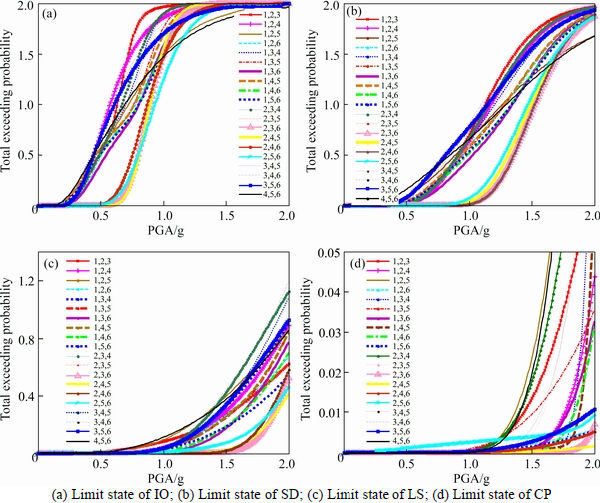
Fig. 12 Total exceeding probability of adjacent structures interconnected by three dampers:
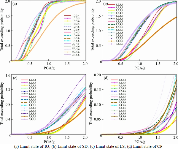
Fig. 13 Total exceeding probability of adjacent structures interconnected by four dampers:
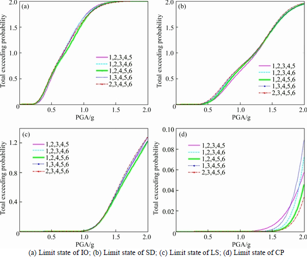
Fig. 14 Total exceeding probability of adjacent structures interconnected by five dampers:
Figure 11 also reveals that, when PGA is small, the arranging positions of the Maxwell dampers have little influence on the structural seismic fragility. With increasing PGA, the optimal positions of the two dampers are the first and sixth floors (legend ��1, 6��) or the third and sixth floor (legend ��3, 6��) for IO and SD performance targets, and the first and sixth floors (legend ��1, 6��) for LS and CP performance targets. Thus it can be seen that, when the arranging number of the Maxwell dampers is two, the optimal positions can be selected as the first and sixth floors (legend ��1, 6��) whose arrangement can get minor total exceeding probability for each performance target. In addition, when the Maxwell dampers are fixed at the first and second floors (legend ��1, 2��), the control effect is the worst.
Figure 12 shows the total exceeding probability of the two adjacent structures under different performance targets when interconnected by three Maxwell dampers. The arrangement of the Maxwell dampers has 20  situations. The legend ��1, 2, 3�� means the three Maxwell dampers are respectively located at the first, second and third floor. The legend ��1, 2, 4�� means the three Maxwell dampers are respectively located at the first, second and fourth floor, others and so on.
Figure 12 presents that different damper arrangements have very different control effects, especially when the three Maxwell dampers are arranged at the floors of ��2,3,6�� ��2,4,5�� ��2,4,6�� and ��2,5,6��, the adjacent structures get minor total exceeding probability under each performance target which propose the necessity to execute the optimized arrangement of the Maxwell dampers. Comprehensive analysis is conducted to the total exceeding probability of the two adjacent structures under different performance targets. The second, fourth and fifth floors (legend ��2,4,5��) can be selected as the optimal positions when arranging three Maxwell dampers on the adjacent structures which propose that the dampers should be arranged uniformly along the structure height and should be avoided intensively arranging in the bottom floors (IO and SD, legend ��1,2,3��), middle floors (LS, legend ��2,3,4��) or the top floors (CP, legend ��4,5,6��) of the shorter building.
Figure 13 shows the total exceeding probability of the two adjacent structures under different performance targets when interconnected by four Maxwell dampers. The arrangement of the Maxwell dampers has 15  situations. The legend ��1,2,3,4�� means the four Maxwell dampers are respectively located at the first, second, third and fourth floor. The legend ��1,2,3,5�� means the four Maxwell dampers are respectively located at the first, second third and fifth floor, others and so on.
Figure 13 reveals that when arranging four Maxwell dampers at the second, fourth, fifth and sixth floor (legend ��2,4,5,6��) of the adjacent buildings, the total exceeding probabilities of the two structures are minimum for IO, SD and LS performance targets. For CP performance target, excepting for legend ��2,3,5,6��, the total exceeding probabilities under different arrangements have little difference and the optimal arrangement is the first, second, third and sixth floor (legend ��1,2,3,6��). By comparing the total exceeding probabilities under different seismic performance targets, the second, fourth, fifth and sixth floors (legend ��2,4,5, 6��) are generally selected as the optimal positions when arranging four Maxwell dampers to the adjacent buildings. Furthermore, the second, third, fifth and sixth floors (legend ��2,3,5,6��) of the adjacent buildings should be avoided to fix up dampers as the worst arranging combination.
Figure 14 shows the total exceeding probability of the two adjacent structures under different performance targets when interconnected by five Maxwell dampers. The arrangement of the Maxwell dampers has 6  situations. The legend ��1,2,3,4,5�� means the five Maxwell dampers are respectively located at the first, second, third, fourth and fifth floor. The legend ��1,2,3,4,6�� means the five Maxwell dampers are respectively located at the first, second, third, fourth and sixth floor, others and so on.
Figure 14 illustrates that when the adjacent buildings are interconnected by five Maxwell dampers, different arrangements have nearly no difference of the total exceeding probability under IO, SD and LS performance targets. Only under CP performance target, when PGA exceeds 1.5 g, the total exceeding probability of the Maxwell dampers under different arrangements have minor difference. Figure 14 presents that, the first, second, fourth, fifth and sixth floors (legend ��1,2,4,5,6��) can be selected as the optimal positions of the five dampers. It is evident that when the number of the arranging dampers is large enough to close to the stories of the shorter building, the necessity to conduct optimal arrangement is very small.
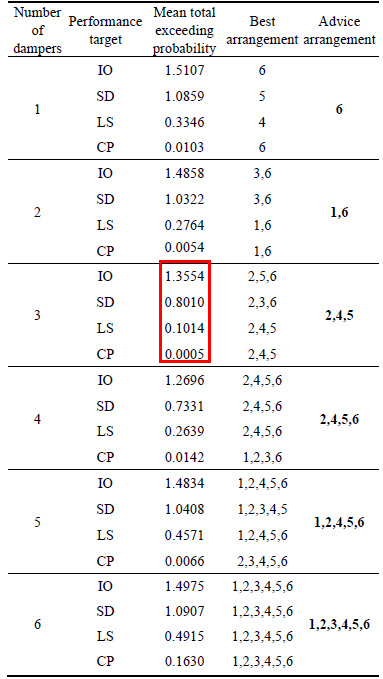
More specifically, Table 3 lists the mean total exceeding probability of the adjacent structures under each performance target when interconnected by the Maxwell dampers under different arranging combinations. Incorporating the aforementioned analysis, it gives the advice of the optimized positions of the Maxwell dampers between the adjacent buildings. The optimal arranging positions can be quantitatively observed from Table 3. Table 3 marks the value of the minimum mean total exceeding probability under each performance levels with the rectangular box.
Table 3 lists that when the arranging number of the Maxwell dampers are determined, the best arrangements of the dampers, which are the arranging combination corresponding to the minimal mean total exceeding probability of the two adjacent structures, under different performance targets are not consistent. After comprehensive analysis, the suggested optimal arranging combinations which can realize preferable control on both the adjacent structures under each seismic performance target is the best arrangement when LS or CP performance targets acquire the minimal mean total exceeding probability. The suggested optimal arranging positions of the Maxwell dampers between the adjacent buildings are set out in the last column of Table 3 (with bold numbers).
Table 3 Results of optimized positions of Maxwell dampers between adjacent buildings
4.3.2 Optimization of arranging numbers
Based on the former analysis of optimized positions of the Maxwell dampers, Fig. 15 displays the total exceeding probability of the adjacent structures under different performance targets, with different damper numbers whose arranging positions have been optimized. The legend ��6�� means that when arranging one damper the optimal position is the sixth floor. The legend ��1,6�� means that when arranging two dampers the optimal positions are the first and sixth floors. The legend ��2,4,5�� means that when arranging three dampers the optimal positions are the second, fourth and fifth floors. The legend ��2,4,5,6�� means that when arranging four dampers the optimal positions are the second, fourth, fifth and sixth floors. The legend ��1,2,4,5,6�� means that when arranging five dampers the optimal positions are the first, second, fourth, fifth and sixth floors. The legend ��1,2,3,4,5,6�� means that each floor of the adjacent buildings is assigned one damper (the number of the dampers is equal to the stories of the shorter building of the adjacent buildings).
Figure 15 plots that when the arranging positions of the Maxwell dampers are determined, it is not the more the dampers are arranged, the better of the control effects can be achieved. When arranging three Maxwell dampers (legend ��2,4,5��), the adjacent structures can get very small total exceeding probability under all kinds of performance targets. However, when dampers are covered each story (legend ��1,2,3,4,5,6��) of the shorter building, the total exceeding probability is extremely big for each performance target. The mean total exceeding probabilities of the adjacent structures in Table 3 (with rectangle) also prove this: except for the mean values of IO and SD when arranging three dampers, the mean total exceeding probabilities are all very small under each performance target in comparison with other arranging numbers. Consequently, the optimal arranged number of the Maxwell dampers is selected as three for the adjacent buildings.
4.4 Example of verification
Using the optimal parameter and optimal arrangement of the Maxwell dampers proposed by the former analysis, the seismic fragility of the adjacent structures interconnected by the optimized Maxwell dampers under different performance targets are compared with the uncontrolled situations to verify the optimization. Figure 16 displays the comparison of the seismic fragility of the adjacent structures with optimized control and without control. The legend with ��-1�� means uncontrolled situation and the legend with ��-2�� means the optimized controlled situation.
Figure 16 shows that, the probability of exceedance under optimized control are much smaller than without control for each performance target of both the adjacent structures, especially for Structure 2 whose controlled effects are more obvious, which verifies the validity of the optimal design of the Maxwell dampers proposed in this work. The optimum design of the Maxwell dampers which contains the optimization of damping parameters and arranging placement is applicable for each seismic performance target of both the adjacent structures, and it proves the realization of performance-based passive control which may bring significative suggestions and reflections for the application of practical engineering.
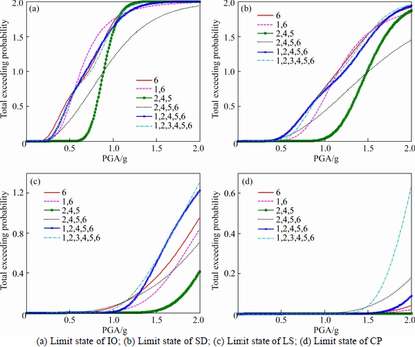
Fig. 15 Total exceeding probability of adjacent structures with different damper arranging numbers:
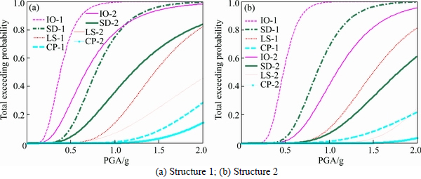
Fig. 16 Verification of optimal design of Maxwell dampers:
5 Conclusions
The performance-based research on the optimal parameters and optimal arrangement (including optimal positions and optimal numbers of the dampers) of the Maxwell dampers connected with some adjacent structures are carried out. Through the theoretical method discussed by simplifying the adjacent buildings to be no torsional response of idealized flat structures, the following conclusions can be found.
1) The damping parameters calculated by the analytical expressions of the Maxwell dampers are not applicable for the well control on the adjacent structures under different performance targets. The optimal parameters should be retrieved in order to make the Maxwell dampers have preferable control effects on the adjacent structures under all kinds of performance targets to realize multi-degree seismic fortification target according to the modern seismic codes.
2) When the adjacent buildings are only interconnected by one Maxwell damper, it should be arranged at the top floor of the shorter building and avoid being arranged at the bottom floor.
3) When the adjacent buildings are interconnected by two Maxwell dampers, they should be arranged at the top and bottom floors of the shorter building and should avoid intensively being arranged at the bottom floors.
4) When the adjacent buildings are interconnected by multiple dampers, they should be arranged uniformly along the height of the shorter building. The dampers should be simultaneously arranged at the bottom, middle and top floors of the shorter building. Centralized arrangement of the Maxwell dampers at any parts of the buildings is prohibited.
5) The number of the dampers placed on the adjacent buildings is not the more the better. The control effect may be the worst when covered by the Maxwell dampers at each floor of the adjacent buildings (the shorter building), and it is not economic as well.
6) The optimization of the arranging positions and arranging numbers for the Maxwell dampers have important influence on the control effects. The more the arranging combinations of the Maxwell dampers between the adjacent structures are, the higher the necessity of the optimal arrangement is.
References
[1] ZHU Hong-ping, Iemura H. A study of response control on the passive coupling element between two parallel structures [J]. International Journal of Structural Engineering and Mechanics, 2000, 9(4): 383-396.
[2] ZHU Hong-ping, YANG Zi-jian, TANG Jia-xiang. Control of the seismic response of two adjacent structures using a damped link [J]. Journal of Vibration Engineering, 2003, 16(1): 57-61. (in Chinese)
[3] ZHU Hong-ping, YU Yong-min, and TANG Jia-xiang. Optimal passive control of primary-auxiliary structures under earthquake excitation [J]. Chinese Journal of Applied Mechanics, 2000, 17(2): 63-69. (in Chinese)
[4] ZHU Hong-ping, Iemura H. A study on interaction control for seismic response of parallel structures [J]. Computers and Structures, 2001, 79(2): 231-242.
[5] ZHU Hong-ping, LIANG Lu. Comparative study of passive optimum control for reducing seismic responses of adjacent structures [J]. Engineering Mechanics, 2005, 22(S): 183-187. (in Chinese)
[6] ZHU Hong-ping, XU You-lin. Optimum parameters of Maxwell model-defined dampers used to link adjacent structures [J]. Journal of Sound and Vibration, 2005, 279(1, 2): 253-274.
[7] ZHU Hong-ping, WENG Shun, CHEN Xiao-qiang. Optimum parameters of Maxwell-defined dampers for reducing the seismic responses of adjacent structures under earthquake [J]. Chinese Journal of Applied Mechanics, 2006, 23(2): 296-300. (in Chinese)
[8] XU You-lin, Zhang W S. Closed-form solution for seismic response of adjacent buildings with LQG controllers [J]. Earthquake Engineering and Structural Dynamics, 2002, 31(2): 235-259.
[9] Bhaskararao A V, Jangid R S. Seismic analysis of structures connected with friction dampers [J]. Engineering Structures, 2006, 28(5): 690-703.
[10] Bhaskararao A V, Jangid R S. Seismic response of adjacent buildings connected with friction dampers [J]. Bulletin of Earthquake Engineering, 2006, 4(1): 43-64.
[11] Bhaskararao A V, Jangid R S. Optimum viscous damper for connecting adjacent SDOF structures for harmonic and stationary white noise random excitations [J]. Earthquake Engineering and Structural Dynamics, 2007, 36(4): 563-571.
[12] Basili M, Angelis M D. A reduced order model for optimal design of 2-mdof adjacent structures connected by hysteretic dampers [J]. Journal of Sound and Vibration, 2007, 306(1, 2): 297-317.
[13] Basili M, Angelis M D. Optimal passive control of adjacent structures interconnected with nonlinear hysteretic devices [J]. Journal of Sound and Vibration, 2007, 301(1, 2): 106-125.
[14] Ok S Y, Song J, Park K S. Optimal design of hysteretic dampers connecting adjacent structures using multi-objective genetic algorithm and stochastic linearization method [J]. Engineering Structures, 2008, 30(5): 1240-1249.
[15] Richardson A, Walsh K K, Abdullah M M. Closed-form equations for coupling linear structures using stiffness and damping elements [J]. Structural Control and Health Monitoring, 2013, 20: 259-281.
[16] Patel C C, Jangid R S. Dynamic response of identical adjacent structures connected by viscous damper [J]. Structural Control and Health Monitoring, 2014, 21: 205-224.
[17] Tubaldi E. Dynamic behavior of adjacent buildings connected by linear viscous/viscoelastic dampers [J]. Structural Control and Health Monitoring, 2015, 22: 1086-1102.
[18] Eurocode 8. Design of structures for earthquake resistance; Part 1: General rules, seismic actions and rules for buildings, EN 1998�C1 [S]. Brussels: European Committee for Standardization, 2005.
[19] GB50011�C2010. Code for seismic design of buildings [S]. Ministry of Housing and Urban-Rural Development. Beijing, China, 2010. (in Chinese)
[20] GB50009�C2012. Load code for the design of building structures [S]. Ministry of Housing and Urban-Rural Development. Beijing, China, 2010. (in Chinese)
[21] GB50010�C2010. Code for design of concrete structures [S]. Ministry of Housing and Urban-Rural Development. Beijing, China, 2010. (in Chinese)
[22] OpenSees, Open system for earthquake engineering simulation [EB/OL]. [2016�C04�C01]. http://opensees.berkeley.edu.
[23] Pacific Earthquake Engineering Research Center-PEER. Next Generation Attenuation Database [EB/OL]. [2016�C04�C01]. http://peer. berkeley. edu/peer_ground_motion_database/24/10/2012.
[24] FEMA 356. Prestandard and commentary for seismic rehabilitation of buildings [S]. ASCE for Federal Emergency Management Agency, Washington, D.C., USA, 2000.
(Edited by FANG Jing-hua)
Cite this article as:
WU Qiao-yun, DAI Jian-zhou, ZHU Hong-ping. Performance-based passive control analysis of adjacent structures: Optimization of Maxwell dampers [J]. Journal of Central South University, 2017, 24(9): 2180�C2197.
DOI:https://dx.doi.org/https://doi.org/10.1007/s11771-017-3627-1Foundation item: Projects(51408443, 51178203) supported by the National Natural Science Foundation of China; Project (K201511) supported by the Science Foundation of Wuhan Institute of Technology, China
Received date: 2015-10-20; Accepted date: 2016-04-01
Corresponding author: ZHU Hong-ping, PhD, Professor; Tel: +86-27-87542631; Fax: +86-27-87542221; E-mail: hpzhu@mail.hust.edu.cn
Abstract: The performance-based passive control analysis of the Maxwell dampers between one 10-story and one 6-story adjacent RC frames is conducted in this work. Not only the optimal parameters but also the optimal arrangements of the Maxwell dampers are proposed based on the optimal target of making the total exceeding probability of the adjacent structures to be minimal. The applicability of the analytical expressions of the Maxwell damper damping parameters under different seismic performance targets are firstly examined and then the preferable damping parameters of the Maxwell dampers are proposed through the extensive parametric studies. Furthermore, the optimal arranging positions and optimal arranging numbers of the Maxwell dampers between the adjacent buildings are derived based on a large number of seismic fragility analyses, as well. The general arranging laws of the Maxwell dampers between the adjacent buildings are generated based on the discussion of the theoretical method through the simplified plane model. The optimal parameters and optimal arrangement of the Maxwell dampers presented make both the adjacent structures have preferable controlled effects under each seismic performance target which can satisfy the requirements of multi-performance seismic resistance of the modern seismic codes.
