

J. Cent. South Univ. (2020) 27: 2311-2323
DOI: https://doi.org/10.1007/s11771-020-4451-6

Dynamic characteristics of gear system under different micro-topographies with the same roughness on tooth surface
YIN Lei(����)1, DENG Chun-long(�˴���)1, YU Wen-nian(������)2,SHAO Yi-min(������)1, WANG Li-ming(������) 1
1. State Key Laboratory of Mechanical Transmission, Chongqing University, Chongqing 400044, China;
2. College of Mechanical Engineering, Chongqing University, Chongqing 400044, China
 Central South University Press and Springer-Verlag GmbH Germany, part of Springer Nature 2020
Abstract:
The topography of gear meshing interfaces is one of the key factors affecting the dynamic characteristics of the gear transmission system. In order to obtain the contact characteristics of meshing gear pair with different surface micro-topographies, an interface feature model and a tribo-dynamics coupling model for the gear system are proposed in this paper. The effects of the gear tooth surface micro-topography on the oil film distribution, contact damping and friction are considered. The time-varying meshing stiffness and the static transmission error are included in the abovementioned models. An exemplary gear pair is analyzed using the proposed models to investigate the influence of the surface micro-topography on the dynamic characteristics of gear system under different micro-topographies and input torque conditions. Simulation results show that the effects of gear tooth micro-topography on the gear dynamic responses (including the friction and the vicious damping at the gear meshing interface and the vibration in the direction of offline of action) are highly dependent on the regularity of tooth surface. The vibration and noise can be significantly controlled by manufacturing a regular gear tooth profiles instead of random profiles.
Key words:
gear tribo-dynamics; coupling model; topography; roughness��
Cite this article as:
YIN Lei, DENG Chun-long, YU Wen-nian, SHAO Yi-min, WANG Li-ming. Dynamic characteristics of gear system under different micro-topographies with the same roughness on tooth surface [J]. Journal of Central South University, 2020, 27(8): 2311-2323.
DOI:https://dx.doi.org/https://doi.org/10.1007/s11771-020-4451-61 Introduction
Gear system is widely used in many industry fields, such as automobile, ship, aerospace. With the increasing demand for high-speed, heavy-duty gearboxes, the dynamic responses of gear system have been paid more and more attentions in the gear design stage. The contact characteristics at the gear meshing interfaces are one of the main factors affecting the dynamic responses of gear transmission system. Moreover, the surface micro- topography is an important characterization of the gear meshing interfaces. Different surface micro- topographies may result in distinct vibration responses of the gear system.
In the literatures, there are a lot of papers dealing with the dynamic characteristics of the gear system. The stiffness excitation imposes a time- varying coefficient on the dynamic equation of the gear system, which actually constitutes the most important attribute of the gear dynamics, forming the basic characteristics and properties of the dynamics [1]. The calculation methods for the time-varying gear mesh stiffness can be classified into two main groups: the finite element method (FEM) [2, 3] and the analytical method based on potential energy principle [4-6].
Compared with the FEM, the potential energy method requires little computational resource. However, it still yields very accurate results that are comparable to FEM results.
Many scholars [7-13] have studied the dynamic characteristics of gear systems with the consideration of various excitation factors such as the time-varying gear mesh stiffness, gear defects, gear tooth profile modifications. MA et al [9] conducted an in-depth investigation on the dynamics of cracked gear system, which mainly includes the prediction of crack propagation path, the evaluation of time-varying mesh stiffness and the modelling of cracked gear systems to obtain their vibration responses. YU et al [11, 12] introduced a general dynamic model for the cylindrical geared rotor system with the consideration of local tooth profile errors and global mounting errors. This model includes a finite element model for shaft structure, a lumped- parameter bearing model and a three-dimensional (3D) gear mesh model. LIANG et al [13] provided a systematic review on the dynamic modelling of gear systems, in which the mesh stiffness evaluation, gear damage modelling and fault diagnosis techniques, gearbox transmission path modelling and method validations were specially studied.
For the study of gear tooth interface contact under lubrication conditions, many scholars [14-16] developed various numerical solution algorithms for the elastohydrodynamic lubrication (EHL) problems. LI [17] proposed a spur gear tribo-dynamic model to achieve a complete coupling between the tribological and the dynamic behavior of the spur gear pair. OUYANG et al [18] used the Runge-Kutta method and the multigrid iterative calculation program to combine the multi-degrees of freedom (DOFs) discrete dynamic model with the infinite line contact thermal elatohydrodynamic lubrication model to study the interaction mechanism between dynamics and tribology. SHI et al [19] proposed an integrated model with the mixed lubrication and dynamic meshing performance for a spur gear pair, and the 3D real roughness of the gears is considered. The effects of the machined process on the mixed lubrication state of the gear pair were investigated. LIU et al [20] developed a numerical model incorporating the lubrication state, tooth surface roughness, residual stress, and the mechanical properties of material to determine the contact fatigue behavior of a wind turbine gear pair.
However, most scholars focused on the contact interface roughness when studying the influence of gear interface contact on the dynamic characteristics of the gear system, whereas the contact interface micro-topography was largely ignored. This may result in the misinterpretation on the effect of the roughness as the micro-topography may also play a significant role in the gear dynamics. Thus, in order to eliminate the influence of surface roughness while studying the individual effect of surface micro-topography, we proposed to investigate the gear dynamic characteristics with the same surface roughness but different surface micro-topographies in this paper. This may provide a new idea for the vibration and noise reduction of the gear system by controlling the surface micro- topography.
This paper is organized as follows. Section 1 summarizes the previous similar work, and concludes their deficiencies and objective of this work. Section 2 establishes the framework of the proposed gear tribo-dynamic coupling model, which mainly combines a gear dynamic model in Section 2.2 and a three-dimensional line-contact elastohydrodynamic lubrication model in Section 2.3. In Section 3, the proposed model is used to analyze the influence of three surface micro- topographies simulated in Section 2.1 on the tribo- dynamic performance under different micro- topographies and different input torques. Conclusions are provided in Section 4.
2 Formulations
In this work, a gear tribo-dynamic model, mainly including a gear dynamic model and a gear 3D EHL model with different surface micro- topography generations, is proposed to study the influence of the surface micro-topography on the dynamic characteristics of the gear system. The solution of the tribo-dynamic coupling equation of the gear system is realized by an iterative loop between the gear dynamic model and the gear 3D EHL model, as shown in Figure 1.
Before the iterative solution, gear parameters like tooth manufacturing error e(t), input torque and speed, are initialized. The time-varying meshing stiffness km(t) is calculated by the potential energy method. The initial values of sliding friction, rolling friction and viscous damping before iteration are set to Fs=0, Cm=0. With these excitations, the vibration equations of the gear dynamic model is solved by the Runge-Kutta method. The vibration motion of the gear system is applied to predicting the sliding velocity of tooth surface u1(t), u2(t) and the radius of curvature in the mesh position R(t). In the meantime, the mesh force FT(t) is calculated using the vibration responses of the gear system, and then substituted into the load distribution model to determine the meshing force of the tooth pair FT(t). With the instantaneous values of u1(t), u2(t), R(t) and FT(t), as well as lubricant properties and micro-��topography of the tooth surface, the governing equations of the mixed lubrication model are solved by the semi-system method��[14, 15]. Then the sliding friction Fs, the rolling friction Fr and the viscous damping Cm at the gear mesh interface are determined by the convergence solution of the mixed lubrication model, which are used in the gear dynamic model to compute the updated dynamic responses.
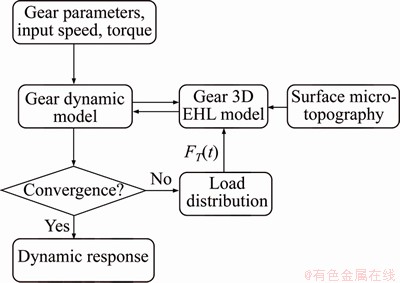
Figure 1 Flowchart of computational method
The entire iterative loop continues until the mesh force of the gear pairs meets the convergence criterion. The convergence criterion is:
 (1)
(1)
where �� denotes the mesh position of the meshing tooth pair in one mesh cycle; K denotes the number of iterative steps; FpK(t��) is the calculated dynamic meshing force at the instantaneous time instant t�� in the K-th iterative step; and err is a predefine convergence threshold, whose value is set to 10-5 in this paper. Thus, whenever the relative error between the dynamic mesh forces calculated in two successive steps is smaller than the predefined convergence threshold, the iteration stops and a stable solution is assumed to be obtained.
2.1 Surface micro-topography
In practice, the tooth surface micro-topography is directly dependent on the cutting accuracy, cutting procedures, regularities, and materials, etc. This paper mainly focuses on three distinct surface micro-topographies that are present in the practical manufacturing. These three cases share the same surface roughness Rq (root mean square value of the surface roughness) and same wavelength L, but their cross sections are different and are represented by random (Case 1), sine (Case 2), and ellipse (Case 3), respectively, as shown in Figure 2. The effect of the surface micro-topography on the friction responses and dynamic responses of gear system is investigated.
2.2 Gear dynamic model
Figure 3 shows a commonly-used spur gear dynamic model [21, 22] with the consideration of the tooth surface friction, i.e. Ffp and Ffg, which represent the friction of driving gear (pinion) and driven gear (gear), respectively. The meshing behavior of the spur gear pair is modeled by the time-varying mesh stiffness km(t) and the mesh damping Cn. The bearing support for each gear is simulated by equivalent supporting stiffness and damping in the x and y directions, i.e. kpx, kgx, kpy, kgy and Cpx, Cgx, Cpy, Cgy.
The driving and driven gears in this model are simplified by rigid bodies [21, 22] with mass mi (i=p, g), moment of inertia Ji, and radius equal to the gear base radius ri. Along the line of action (LOA), the rotational motion and the translational motion in the y direction of the two gears are coupled by a spring-damper unit. km is simulated as the time-varying meshing stiffness of the gear pair, and cn is the meshing damping of the gear pair. e is the static transmission error, which mainly includes tooth elastic deformation under static loaded condition and tooth manufacturing error. The rotational freedom and the translational freedom in the x direction of the two gears are coupled in the offline of action (OLOA) direction. The governing equations of the above-mentioned gear model are:
 (2)
(2)
 ���������� (3)
 (4)
(4)
 (5)
(5)
 (6)
(6)
 (7)
(7)
where n is the number of meshing tooth pair; Tiis the external load acting on gear i (i=p,g,representing the pinon and gear respectively);  and
and  denote the torsional vibration velocity and acceleration of gear i;
  i and
i and  i represent the translational vibration velocity and acceleration in the OLOA direction of gear i, respectively;
  i and
i and  i represent the translational vibration velocity and acceleration in the LOA direction of gear i, respectively; Ri is the radius at the meshing position of gear i. The frictional forces Ffp and Ffg of the driving and driven gears are calculated by the mixed EHL model that will be introduced in Section 2.3. The dynamic meshing force Fp can be expressed as:

 (8)
(8)
In a typical meshing process of spur gear pair, the number of tooth pairs in the mesh zone changes periodically. Considering a gear pair with a normal contact ratio (i.e. contact ratio between 1 and 2), the number of meshing tooth pair alternates between 1 and 2, and the entire mesh zone can be divided as the single tooth pair contact (STC) zone and the double tooth pair contact (DTC) zone. The total gear dynamic mesh force can be expressed as the sum of the mesh forces of all tooth pairs in the mesh zone:
 (9)
(9)
where FT1 and FT2 represent the mesh forces of the 1st and 2nd meshing tooth pair, and FT2=0 when there is only one tooth pair in mesh. Using the inter-tooth load distribution model [22, 23], the mesh force of each tooth pair is obtained:

 (10)
(10)
where ki is the time-varying mesh stiffness [4-6] of the i-th meshing tooth pair (i=1, 2). ci is the mesh damping of the i-th tooth pair (i=1, 2), which is normally assumed as a parameter dependent on ki [24]. The calculation formula is:
 (11)
(11)
where Vi is the initial relative vibration velocity between the meshing teeth and a=1-0.022Vi0.36. In Eq. (11), �� and  represent the relative displacement and velocity of the i-th tooth pair (i=1, 2) along the LOA direction, respectively, which can be expressed by:
 (12)
(12)
 (13)
(13)
where ei denotes the displacement excitation due to the tooth profile deviations (with respect to the ideal involute profile) for the i-th tooth pair (i=1, 2) during the meshing process, whereas  i represents the derivative of ei, which is the velocity excitation.
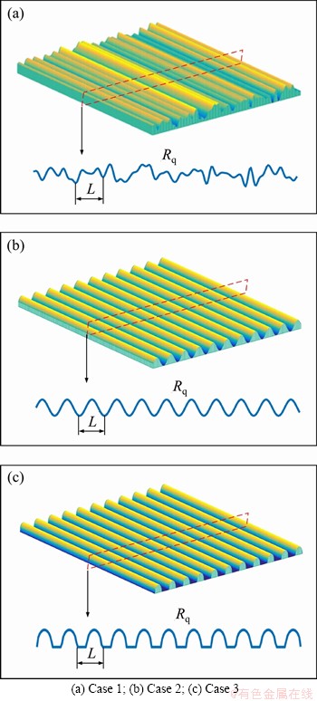
Figure 2 Three types of surface micro-topography:
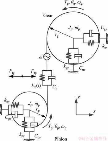
Figure 3 Gear dynamic model [21, 22]
2.3 Gear 3D EHL model
Affected by factors such as the load and the sliding speed of the meshing tooth surfaces, the viscosity of the lubricating oil and the roughness of the tooth surface, the lubrication condition can be classified into three cases: elastohydrodynamic lubrication, mixed lubrication and boundary lubrication. Among these factors, the load is the tooth meshing force evaluated through Eq. (11). The sliding speed of a meshing tooth pair is the difference of their linear velocities in the OLOA direction, i.e. up(t) and ug(t), which can be expressed as:
 (14)
(14)
 (15)
(15)
where  i(t) is the linear velocity due to the nominal rotation of gear i (i=p, g) in the OLOA direction, and is defined as i(t)=-Ri(t)��i, where ��iis its nominal rotational speed.
 and i(t) (i=p,g) are the velocity components in the OLOA direction generated by the rotational and translational vibrations, respectively.
There exists both hydrodynamic oil film and asperity contact at the gear meshing position under the mixed lubrication condition. In the region where there is no asperity contact, the gear meshing pair is separated by a layer of lubricant film to form the full film lubrication. Gear meshing is usually characterized by a line contact with lubrication oil flowing between the meshing teeth. Based on the Reynolds equation [12-14], the general form of the 3D line contact EHL model is expressed as:
 (16)
(16)
where x is in the sliding direction of the meshing tooth and y is in the gear axial direction; P and h denote the oil film pressure and the thickness, respectively; �� represents the lubricant density; the rolling speed ur is the instantaneous average speed of the meshing tooth, i.e. ur=1/2[up(t)+ug(t)]; ��* is the equivalent viscosity, considering the non- newton characteristics of oil shear thinning, and is obtained by the Ree-Eying model [25]:
 (17)
(17)
where ��0 is the reference shear stress of the lubricant; ��m is the average viscous shear stress of the lubricant; �� is the viscosity of the lubricant at a low shear rate calculated by the Roelands�� formula.
The rheological properties of the oil film are affected by the topography of the tooth surface. The oil film thickness is very thin at the peak positions of surface roughness, where tooth contact may occur. Thus, the lubrication condition is converted into the mixed lubrication. At this specific meshing position, the general form of the Reynolds equation cannot be solved due to the topography of the tooth surface, and the elastic contact theory is required. To achieve a unified solution for the entire contact region, when the oil film thickness is zero, all the fluid hydrodynamic terms in the Reynolds equation are closed so that it is satisfied by the solution of asperity contact pressure [16, 17]. This is equivalent to simplifying the Reynolds equation to [26]:
 (18)
(18)
Since Eq. (17) is a special case of Eq. (8), in the numerical solution of the EHL, the pressure automatically satisfies the continuity condition at the border between the hydrodynamic and the asperity contact regions, and no additional setting is required. In this way, the mixed lubrication can be solved by the same iterative loop.
The mathematical equation for the oil film thickness in the EHL zone is:
 (19)
(19)
where Rx denotes the equivalent radius of curvature of the two teeth at the meshing point, which can be expressed as 1/Rx=1/Rp+1/Rg; �� represents the geometric distribution of the composite micro-topography of the driving and driven gears at the meshing point, as shown in Figure 1; V is the deformation of the tooth surface, calculated by the DC-FFT method [27], and the calculation formula is as follows:
 (20)
(20)
where Pf is the hydrodynamic pressure, which can be obtained by solving coupled Eqs. (16), (19) and (20); Pc is the asperity pressure, which can be determined by solving coupled Eqs. (18)-(20); �� and S are the additional coordinates in the x and y axes, respectively; E' denotes the equivalent elastic modulus of the gear pair, and �� represents the computational domain at the meshing point.
The numerical solution of the mixed lubrication problem is carried out under a given load condition, and the solved pressure must satisfy the load balance condition. The load balance equation is:
 (21)
(21)
when h��0, P is the hydrodynamic pressure, whereas when h=0, P is the asperity contact pressure. In the gear transmission system, FT is the tooth force of a single tooth pair, obtained by Eq. (11).
Under the EHL condition, the friction at the gear mesh interface is generated by the viscous shear stress of the oil film between teeth. The viscous shear stress of the oil film is composed of Poiseuille and Couette flows, which changes linearly in the z direction (i.e. along the film thickness direction), and is written as:

 (22)
(22)
Due to the non-smooth meshing interface, asperity contact may occur at the rough peak positions under the external load to form the mixed lubrication. Under this condition, the friction force of the gear system is composed of two parts. One is the viscous shear force of the oil film between the meshing teeth, and the other is the asperity friction caused by the direct contact of the rough peak to break the oil film. Based on the numerical calculation of the mixed lubrication, the shear force of the oil film in the middle layer is used as the friction force of the oil film, and the friction force at any time of the gear mesh interface is:
 (23)
(23)
where M and N are the numbers of grid in the x and y directions of the computational domain, respectively; A is the area of grid element; ��ij denotes the equivalent shear force at the intermediate layer of oil film (where z=0.5h in Eq. (22)) on the grid node (i, j); Pcij is the asperity contact pressure on the grid node (i, j), and the friction coefficient of the asperity contact ��b is assumed to be 0.1 [28, 29]. Eqs. (8) and (22) are substituted into Eq. (23), and the friction forces at the gear mesh interface are obtained by:

 (24)
(24)
 (25)
(25)
The friction coefficient is:
 (26)
(26)
The viscous damping Cm(t), the sliding frictional force Fs(t) and the rolling frictional force Fr(t) of the meshing tooth pair [16] are calculated using the convergent oil film pressure p and the film thickness h of the mixed lubrication model as follows:
 (27)
(27)
 (28)
(28)
 (29)
(29)
It can be seen from Eqs. (27)-(29) that the viscous damping Cm(t) is proportional to the equivalent viscosity of the lubricant and inversely proportional to the oil film thickness. The sliding friction force Fs(t) increases with the viscous damping Cm, the relative sliding speed of the tooth surface ug��up, and the asperity contact pressure Pcij. The rolling friction Fr(t) is proportional to the oil film thickness h and the oil film pressure gradient along the tooth sliding direction.
The friction Eq. (25) calculated by the solutions of the mixed lubrication is substituted into the vibration Eq. (8) of the gear system to obtain the gear tribo-dynamic coupling equations:


 (30)
(30)
 (31)
(31)


 (32)
(32)


 (33)
(33)
 (34)
(34)


 (35)
(35)
As can be seen from Eqs. (30)-(35), the rotational freedom and the translational freedom along the OLOA direction are coupled in Eqs. (32) and (35) by the friction force at the gear meshing interface, so that the translational vibration along the OLOA direction interacts with the torsional vibration of the gear system. Since the meshing force is a function of the displacement yi and velocity i along the LOA direction, as shown in Eq. (3), six DOFs are coupled in Eqs. (30), (33) by the meshing force and the friction force at the gear meshing interface. The torsional vibration of the gear system interacts with all translational vibrations of the gear system.
3 Simulation and discussion
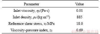
The tribo-dynamic model of the gear system considering the same roughness and different types of micro-topography under lubrication condition is established in this paper. The main design parameters of the gear pair (pinion and gear) in the present case are shown in Table 1, and the lubricant properties are shown in Table 2.
Table 1 Main parameters of gear pair
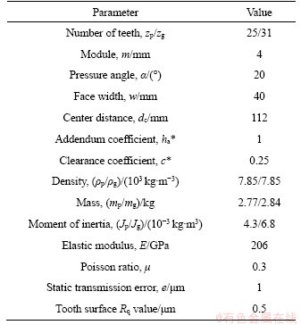
Table 2 Lubricant properties
The dynamic characteristics of gear system are investigated under the working condition of the input torque 500 N��m and speed 1000 r/min. The gear dynamic model is shown in Figure 3. The equivalent bearing supporting stiffnesses of driving and driven gear in the x and y direction are kpx=kgx=5.8��108 N/m and kpy=kgy=5.8��108 N/m respectively, and the equivalent dampings are cpx=cgx=6.5��103 N��s/m and cpy=cgy=6.5��103 N��s/m, respectively.
3.1 Gear mesh stiffness and mesh force
The potential energy method [4-6, 22-24] is used to calculate the time-varying mesh stiffness of each meshing tooth pair as well as the gear pair, and the results are shown in Figure 4. The red line shows the gear mesh stiffness (i.e. km) in four mesh cycles, whereas the dashed blue and green lines show the mesh stiffness of tooth pairs 1 and 2 in each cycle, respectively. It should be noted that the mesh stiffness of gear pair is the summation of mesh stiffnesses of all engaged tooth pairs. The region where k2 = 0, is the so-called STC region as the tooth pair 2 is not engaged in this region, and the total mesh stiffness is distinctly less than that in the DTC region.
The total mesh stiffness of the gear pair is substituted into the tribo-dynamic coupling equation to obtain the vibration responses of the gear system, based on which the mesh forces of the gear pair and all engaged tooth pairs can be determined through Eqs. (10) and (11).
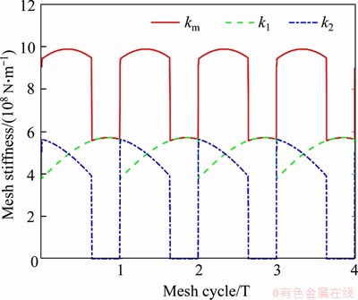
Figure 4 Time-varying mesh stiffness of each meshing tooth pair and gear pair (T=0.0024 s)
The dynamic mesh forces are shown in Figure 5. The red line shows the total mesh force of the gear pair, whereas the dashed blue and green lines show the mesh forces of the tooth pairs 1 and 2, respectively. It should be noted that the mesh force of gear pair is the summation of mesh forces of all engaged tooth pairs. It can be found that the fluctuation amplitude of the total mesh force first decreases and then increases, and the main reason is that this mesh process is from the DTC region to the STC region.

Figure 5 Dynamic tooth mesh force of each meshing tooth pair and gear pair (T=0.0024 s)
3.2 Friction and damping between different types of the surface micro-topography
The vibration responses obtained by the gear dynamic model is used to determine the dynamic mesh forces, sliding velocity of the tooth surface and the radius of curvature at the mesh position. These values together with lubricant properties and the micro-topography at the gear mesh interface are applied in the mixed lubrication model to predicting the lubricant film thickness, pressure distribution, and friction responses of the gear system. For comparison purpose, we also provide the case where the tooth surface is smooth as shown in Figures 6 and 7.
The influence of the geometric distribution of the surface micro-topography at a wavelength L of 20 ��m and a surface roughness Rq value of 1 ��m on the viscous damping is investigated in Figure 6. The red, green and blue lines indicate the viscous damping corresponding to the surface micro- topography Cases 1, 2 and 3, respectively, whereas the black line is to the smooth surface. Table 1 shows the damping values at five critical points (A, B, C, D and E represent the entry point, transition point from STC to DTC, pitch point, transition point from DTC to STC, and existing point) for the three cases studied. It can be found that damping value goes higher as the tooth surface micro- topography becomes regular from Cases 1 to 3. The main reason is that the roughness peaks are more evenly concentrated around the median line in Case 3 than in Case 1, which results in a closer contact between the gear meshing interfaces, and thus a thinner oil film in Case 3 than in Case 1. It is also noticed that the smooth surface yields higher damping than the three rough surface cases, which is possibly due to the thinnest oil film generated between the smooth meshing interfaces. Another obvious finding is that the damping values in the DTC region are higher than those in the STC region. This is because the oil film is more easily formed in the DTC region as the sliding speed in this region is smaller than that in the STC region.
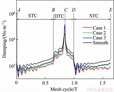
Figure 6 Comparison of viscous damping among different types of surface micro-topography (T=0.0024 s)
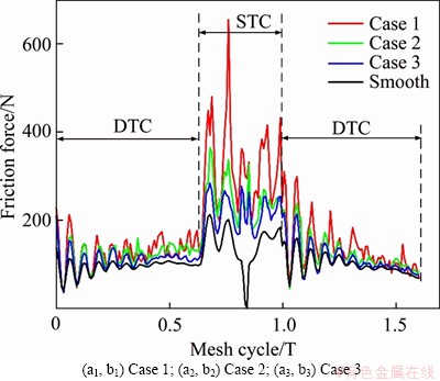
Figure 7 Comparison of friction forces among different types of surface micro-topography (T=0.0024 s)
Table 3 Damping values at five critical points in a mesh cycle among different cases

Figure 7 shows the effect of the geometric distribution of the surface micro-topography at a wavelength L of 20 ��m and a surface roughness Rq value of 1 ��m on the friction force. The red, green and blue lines indicate the friction forces corresponding to the surface micro-topography Cases 1, 2 and 3, respectively, whereas the black line is to smooth surface. It can be noticed that, for the three rough surface cases, the friction force in the DTC region is smaller than in the STC region. As the geometric distribution of surface micro-topography Cases 1, 2 and 3 successively slows down, the roughness peak decreases, which results in the weakening of the asperity contact. Thus, the corresponding friction force gradually decreases from Cases 1 to 3. It is also noticed that the smooth surface yields the lowest friction force no matter in the STC or the DTC region, which is due to the ��smooth�� contact between the meshing interfaces. Especially, at the pitch point, the friction force is zero between the smooth meshing interfaces.
In the following part, the influence of the wavelength L (with a fixed Rq) on the friction force and viscous damping at the gear mesh interface is studied under the three types of surface micro- topography.
Figures 8(a1)-(a3) show the friction force of the three surface micro-topographies Cases 1, 2 and 3 depicted in Figure 2 with different amounts of wavelength L, where Figures 8(b1)-(b3) show their viscous damping. The friction force and viscous damping of the three surface micro-topographies are averaged along the mesh cycle, and the effects of the type and wavelength of the micro-topography on the average friction force and the effects of the type and wavelength of the micro-topography on the average friction force and the damping are investigated.
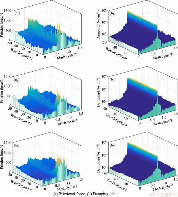
Figure 8 Friction force (a) and viscous damping (b) with different types of wavelength micro-topography (T=0.0024 s):
The variations of the average friction force among different types of the surface micro-��topography over a range of wavelengths are illustrated in Figure 9(a), respectively. It can be seen that when the wavelength is small, the difference in the average friction force corresponding to the surface micro-topography Cases 2 and 3 is slight. When the wavelength is large, the average friction force for the surface micro-topography Case 2 is greater than that of Case 3. With the increase of wavelength, the average frictional force of the surface micro- topography Case 1 slightly decreases to a certain point (around 30 ��m of the wavelength), and then significantly fluctuates in the vicinity due to the randomness of the micro-topography in Case 1. The average frictional forces for the surface micro-topography Case 2 and Case 3 abruptly decrease to a minimum value (around 13 ��m of the wavelength) and then increase with the wavelength. This demonstrates the critical role of surface micro-topography wavelength on the frictional effect between gear meshing interfaces.
The variations of the average viscous damping value among different types of the surface micro-��topography over a range of wavelengths are illustrated in Figure 9(b). It can be found that the average viscous damping is less affected by the surface micro-topography wavelength, and the average viscous damping corresponding to the surface micro-topography Case 2 is similar to that of Case 3, but larger than that of Case 1.
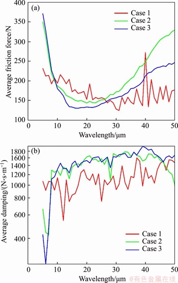
Figure 9 Averaged values in a mesh cycle with respect to wavelength for:
3.3 Dynamic characteristics under different types of surface micro-topography
The effects of different types of the surface micro-topography on the dynamic characteristics of the gear system are investigated using the proposed model.
Figure 10 shows the effect of the three surface micro-topographies at a wavelength L of 20 ��m on the RMS of displacement response for the driving gear along the OLOA direction with respect to the roughness value and the input torque. It can be found that the RMS value decreases from the surface micro-topography Case 1 to 3, and the decrement is increasing as the torque increases. Moreover, the difference in RMS values between any regular surface (i.e. Case 2 or 3) and random surface (i.e. Case 1) is higher than that between two regular surfaces (i.e. Case 2 and 3). It is also found that the roughness value has a comparatively slight effect on the dynamic response.
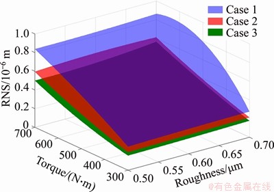
Figure 10 RMS of displacement response for driving gear in OLOA direction with respect to surface roughness Rq and input torque
4 Conclusions
Considering the time-varying meshing stiffness, the static transmission error, the geometric distribution of the surface micro-topography and the shearing effect of the oil film, a gear tribo-dynamic coupling model is established based on governing equations of a six DOFs gear dynamic model and a 3D EHL model. The solution of the tribo-dynamic coupling model is realized through an iterative loop till convergence. The proposed coupling model is applied to investigating the influence of the geometric distribution of the surface micro-topography at the gear contact interface on the dynamic characteristics of the gear system under lubrication condition. The following conclusions can be drawn:
1) The viscous damping at the meshing interface goes higher as the tooth surface topography turns from random (Case 1) to regular (Cases 2 and 3), and the smooth surface has the highest damping. On the contrary, the frictional force goes lower with the smoothness of the tooth surface.
2) For the regular tooth surface micro- topography, its wavelength plays a critical role in the frictional effect between gear meshing interfaces, and the frictional force drops to the minimum at a certain wavelength (around 13 ��m for the case studied).
3) The dynamic responses in the OLOA direction decrease as the tooth surface micro-��topography becomes regular (i.e. from Cases 1 to 3), meaning that manufacturing a regular shape (instead of a random shape) of tooth profiles is preferred to reduce the vibration of gear systems.
Our future work focuses on an experimental study of the gear dynamic behavior with different types of micro-topographies to verify the theoretical findings via this study.
References
[1] CAO Zheng, CHEN Zai-gang, JIANG Han-jun. Nonlinear dynamics of a spur gear pair with force-dependent mesh stiffness [J]. Nonlinear Dynamics, 2020, 99(2): 1227-1241. DOI: 10.1007/s11071-019-05348-0.
[2] MA Hui, PANG Xu, FENG Ran-jiao, SONG Rong-ze, WEN Bang-chun. Fault features analysis of cracked gear considering the effects of the extended tooth contact [J]. Engineering Failure Analysis, 2015, 48: 105-120. DOI: 10.1016/j.engfailanal.2014.11.018.
[3] MA Hui, LI Zhan-wei, FENG Meng-jiao, FENG Ran-jiao, WEN Bang-chun. Time-varying mesh stiffness calculation of spur gears with spalling defect [J]. Engineering Failure Analysis, 2016, 66: 166-176. DOI: 10.1016/ j.engfailanal.2016.04.025.
[4] YU Wen-nian, SHAO Yi-min, MECHEFSKE C K. The effects of spur gear tooth spatial crack propagation on gear mesh stiffness [J]. Engineering Failure Analysis, 2015, 54: 103-119. DOI: 10.1016/j.engfailanal.2015.04.013.
[5] YU Wen-nian, MECHEFSKE C K. Analytical modeling of spur gear corner contact effects [J]. Mechanism and Machine Theory, 2016, 96: 146�C164. DOI: 10.1016/j.mechmachtheory. 2015. 10.001.
[6] YU Wen-nian, MECHEFSKE C K. A new model for the single mesh stiffness calculation of helical gears using the slicing principle [J]. Iranian Journal of Science and Technology: Transactions of Mechanical Engineering, 2019, 43(1): 503-515. DOI: 10.1007/s40997-018-0173-x.
[7] SUN Yan-ning, MA Hui, HUANGFU Yi-fan, CHEN Kang-kang, CHE Lin-yang, WEN Bang-chun. A revised time-varying mesh stiffness model of spur gear pairs with tooth modifications [J]. Mechanism and Machine Theory, 129: 261-278. DOI: 10.1016/j.mechmachtheory.2018.08. 003.
[8] CAO Zheng, SHAO Yi-min, RAO Meng, YU Wen-nian. Effects of the gear eccentricities on the dynamic performance of a planetary gear set [J]. Nonlinear Dynamics, 2018, 91: 1-15. DOI: 10.1007/s11071-017-3738-0.
[9] CHEN Zai-gang, ZHAI Wan-ming, WANG Kai-yun. Vibration feature evolution of locomotive with tooth root crack propagation of gear transmission system [J]. Mechanical Systems and Signal Processing, 2019, 115: 29-44. DOI: 10.1016/j.ymssp.2018.05.038.
[10] MA Hui, ZENG Jin, FENG Ran-jiao, PANG Xu, WANG Qi-bin, WEN Bang-chun. Review on dynamics of cracked gear systems [J]. Engineering Failure Analysis, 2015, 55: 224-245. DOI: 10.1016/j.engfailanal.2015.06.004.
[11] YU Wen-nian, MECHEFSKE C K, TIMUSK M. The dynamic coupling behaviour of a cylindrical geared rotor system subjected to gear eccentricities [J]. Mechanism and Machine Theory, 2017, 107: 105-122. DOI: 10.1016/ j.mechmachtheory.2016.09. 017.
[12] YU Wen-nian, MECHEFSKE C K, TIMUSK M. Effects of tooth plastic inclination deformation due to spatial cracks on the dynamic features of a gear system [J]. Nonlinear Dynamics, 2017, 87: 2643-2659. DOI: 10.1007/s11071- 016-3218-y.
[13] LIANG Xi-hui, ZUO Ming-jian, FENG Zhi-peng. Dynamic modeling of gearbox faults: A review [J]. Mechanical System and Signal Processing, 2018, 98: 852-876. DOI: 10.1016/ j.ymssp.2017.05.024.
[14] LARSSON R. Transient non-Newtonian elastohydrodynamic lubrication analysis of an involute spur gear [J]. Wear, 1997, 207(1, 2): 67-73. DOI: 10.1016/S0043-1648(96)07484-4.
[15] HU Yuan-zhong, WANG Hui, WANG Wen-zhong, ZHU Dong. A computer model of mixed lubrication in point contacts [J]. Tribology International, 2001, 34(1): 65-73. DOI: 10.1016/ S0301-679X(00)00139-0.
[16] LI Sheng, KAHRAMAN A. A tribo-dynamic model of a spur gear pair [J]. Journal of Sound and Vibration, 2013, 332(20): 4963-4978. DOI: 10.1016/j.jsv.2013.04.022.
[17] LI Sheng. A thermal tribo-dynamic mechanical power loss model for spur gear pairs [J]. Tribology International, 2015, 88: 170-178. DOI: 10.1016/j.triboint.2015.03.022.
[18] OUYANG T, HUANG Hao-zhong, ZHANG Ning, MO Chun-lan, CHEN Nan. A model to predict tribo-dynamic performance of a spur gear pair [J]. Tribology International, 2017, 116: 449-459. DOI: 10.1016/j.triboint.2017.08.005.
[19] SHI Xiu-jiang, SUN Wen, LU Xi-qun, MA Xuan, ZHU Dong, ZHAO Bin, HE Tao. Three-dimensional mixed lubrication analysis of spur gears with machined roughness [J]. Tribology International, 2019, 140: 105864. DOI: 10.1016/j.triboint.2019.105864.
[20] LIU He-li, LIU Huai-ju, ZHU Cai-chao, SUN Zhang-dong, BAI Hou-yi. Study on contact fatigue of a wind turbine gear pair considering surface roughness [J]. Friction, 2020, 8(3): 553-567. DOI: 10.1007/s40544-019-0297-z.
[21] YU Wen-nian, MECHEFSKE C K, TIMUSK M. Influence of the addendum modification on spur gear back-side mesh stiffness and dynamics [J]. Journal of Sound and Vibration, 2017, 389: 183-201. DOI: 10.1016/j.jsv.2016.11.030.
[22] CHEN Zai-gang, SHAO Yi-min. Dynamic simulation of spur gear with tooth root crack propagating along tooth width and crack depth [J]. Engineering Failure Analysis, 2011, 18(8): 2149-2164. DOI: 10.1016/j.engfailanal.2011.07. 006.
[23] YU Wen-nian, MECHEFSKE C K, TIMUSK M. A new dynamic model of a cylindrical gear pair with localized spalling defects [J]. Nonlinear Dynamics, 2018, 91(4): 2077-2095. DOI: 10.1007/s11071-017-4003-2.
[24] YANG D C H, SUN Z S. A rotary model for spur gear dynamics [J]. Journal of Mechanisms, Transmissions, and Automation in Design, 1985, 107(4): 529-535. DOI: doi.org/10.1115/1.3260759.
[25] BOU-CHAKRA E, CAYER-BARRIOZ J, MAZUYER D, JARNIAS F, BOUFFET A. A non-Newtonian model based on Ree�CEyring theory and surface effect to predict friction in elastohydrodynamic lubrication [J]. Tribology International, 2010, 43(9): 1674-1682. DOI: 10.1016/j.triboint.2010. 03.016.
[26] LI Sheng, KAHRAMAN A. Prediction of spur gear mechanical power losses using a transient elastohydrodynamic lubrication model [J]. Tribology Transactions, 2010, 53(4): 554-563. DOI: 10.1080/ 10402000903502279.
[27] CHEN W W, LIU S B, WANG Q J. Fast Fourier transform based numerical methods for elasto-plastic contacts of nominally flat surfaces [J]. Journal of Applied Mechanics, Transactions ASME, 2008, 75(1): 011022. DOI: 10.1115/1.2755158.
[28] WU Shi-feng, CHENG H S. A friction model of partial-EHL contacts and its application to power loss in spur gears [J]. Tribology Transactions, 1991, 34(3): 398-407. DOI: 10.1080/10402009108982050.
[29] LAI W T, CHENG H S. Temperature analysis in lubricated simple sliding rough contacts [J]. ASLE transactions, 1985, 28(3): 303-312. DOI: 10.1080/05698198508981625.
(Edited by ZHENG Yu-tong)
���ĵ���
����ֲڶ���ͬ�IJ�ͬ��������ò�³���ϵͳ�Ķ�̬����
ժҪ����������������ò��Ӱ����ִ���ϵͳ����ѧ���Ե���Ҫԭ��֮һ�����Ľ�����һ�������������������Ժ�Ħ������ѧ�����ģ�ͣ�ּ���о����в�ͬ��������ò�ij��ֶ���ѧ���ԡ���ģ�Ϳ����˳�����ò�������������Ĥ��ȷֲ����Ӵ������Լ�Ħ������Ӱ�죬ͬʱ������ʱ�����ϸնȺ;��������ȼ���Ԫ�ء���һ�Գ��ָ�Ϊ�о��������ø�ģ���о��˲�ͬ��������ò����ͬ����ֲڶ��Լ���ͬ���ع����¸ó��ָ��Ķ���ѧ��Ϊ����������������������ò�ļ��ι����ֱ��Ӱ����ֶ���ѧ��Ӧ(��������Ħ��������������Լ�Ħ�����������)��ͨ���ӹ�������(�������)�ij�������Ч���ͳ���ϵͳ����������
�ؼ��ʣ�����Ħ������ѧ�����ģ�ͣ���������ò������ֲڶ�
Foundation item: Projects(51905053, 51805051) supported by the National Natural Science Foundation of China; Project(cstc2019jcyj-bshX0119) supported by the Chongqing Postdoctoral Science Foundation, China
Received date: 2019-12-26; Accepted date: 2020-05-13
Corresponding author: SHAO Yi-min, PhD, Professor; Tel: +86-13628303673; E-mail: ymshao@cqu.edu.cn; ORCID: https://orcid.org/ 0000-0002-2698-7005
Abstract: The topography of gear meshing interfaces is one of the key factors affecting the dynamic characteristics of the gear transmission system. In order to obtain the contact characteristics of meshing gear pair with different surface micro-topographies, an interface feature model and a tribo-dynamics coupling model for the gear system are proposed in this paper. The effects of the gear tooth surface micro-topography on the oil film distribution, contact damping and friction are considered. The time-varying meshing stiffness and the static transmission error are included in the abovementioned models. An exemplary gear pair is analyzed using the proposed models to investigate the influence of the surface micro-topography on the dynamic characteristics of gear system under different micro-topographies and input torque conditions. Simulation results show that the effects of gear tooth micro-topography on the gear dynamic responses (including the friction and the vicious damping at the gear meshing interface and the vibration in the direction of offline of action) are highly dependent on the regularity of tooth surface. The vibration and noise can be significantly controlled by manufacturing a regular gear tooth profiles instead of random profiles.
