
J. Cent. South Univ. Technol. (2008) 15: 906-910
DOI: 10.1007/s11771-008-0165-x
![]()
Displacement and deformation analysis for uplift piles
YANG Xiao-li(����), ZOU Jin-feng(���)
(School of Civil and Architectural Engineering, Central South University, Changsha 410075, China)
Abstract:
On the assumptions that the shear resistance increases linearly with increasing shear displacement between the uplift pile and surrounding soil, that the axis force is distributed as parabola along the pile length, that elastic distortion occurs when the pile is loaded, that the displacement of pile is in accord with that of the soil, and that the uplift pile failure is regarded as the soil failure, a rational calculation method was proposed for calculating the deformation, ultimate displacement and shear resistance of piles. The distributions of frictional resistance and the shear displacement along the pile length were obtained with the method. The comparisons were made between the measurement results and the present results. The present theoretical results agree well with the measurement results, with the average difference being less than 12% before failure. The comparisons show that the proposed method is reasonable for uplift design and engineering construction of piles.
Key words:
uplift pile; load transfer mechanism; displacement; deformation��
1 Introduction
The uplift pile has been widely used as an effective reinforcement in civil engineering for long time. However, the interaction mechanism between the pile and the soil mass is not well understood, and the uplift pile design is still empirical so far, especially the deformation and the displacement. A common method to verify part of the uplift pile design is the pullout test, but it is difficult and expensive, and the working conditions of the rock and soil around the pile are always unknowable. Many researchers have worked on this field. For example, HUANG et al[1] proposed a theoretical method to predict the displacement of pile, and LEHANE et al[2] and CAIRO and CONTE[3] provided the model of frictional pile. However, the literature of the pile displacement and deformation is limited, which is contributed to the fact that the deformation and displacement are restricted by not only the material made of the pile but also the parameters of the soil and rock. The deformation and displacement are more uncertain than the load capacity of pile. In order to improve the uplift pile design, it is necessary to have a good understanding about the calculation of deformation and the ultimate displacement in the uplift pile, especially in the important projects[4-6]. At the same time, the limit analysis has been developed rapidly[7-9]. The ultimate displacement of uplift pile in soil is helpful for the design because the ultimate displacement provides the essential information related to the working status of the uplift pile, which is a reasonable basis for the adjustment of the design.
In order to overcome the above defects, an analytical model based on an improved model for uplift pile was developed. The development of the model is based on the interaction behavior description that the shear resistance increases linearly with increasing shear displacement between the uplift pile and the surrounding soil, that the axis force is distributed as parabola along the pile length, that only elastic distortion occurs when the load is operated on the pile, and that the displacement of pile is in accord with that of the soil. A back analysis method was proposed to calculate the shear displacement and friction force of the interface media. By using the developed model, the interaction behavior of the uplift pile and the surrounding soil mass was investigated, which provides a way of evaluating the supporting performance quantitatively.
2 Theoretic model2.1 Basic assumptions
According to the previously published achievements, the load is supported by pile and soil when the uplift works[5]. The deformation between the pile and the soil is harmonious[10-11]. The failure of pile is regarded as failure of the soil that strength is up to the ultimate strength. So the major theoretic hypotheses are as follows.
1) It is assumed that there is only shear resistance at the surface of the pile embedded in soil mass. Consequently, the potential contribution of the shaft resistance of the ground, which may lie above the soil, is not taken into account, and neither is the possible contribution of the pile tip.
2) The strength at the interface between the soil and pile is assumed to be the soil strength. This means that there are not disturbance, modification, alteration of the surface of the soil in contact with the uplift pile. It also means that the strength of the material that the pile is made of concrete or steel is greater than the strength of the soil.
3) The shear resistance increases linearly with the shear displacement between the pile and the surrounding soil. The axis force supported by the tension pile is distributed as parabola along the uplift pile.
2.2 Deformation of uplift pile
According to the assumptions, the ultimate displacement of uplift pile can be expressed as
S=Se+Ss (1)
where S, Se and Ss are the ultimate displacement of the uplift pile, the elastic deformation of the pile and the shear displacement between the soil and the uplift pile, respectively.
According to the assumptions, the deformation of uplift pile is mostly the elastic deformation when the uplift load acts on the pile. The loads equal P and 0 at the top and the bottom of the pile, respectively. The relationship is shown in Fig.1.
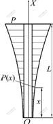
Fig.1 Parabolic distribution of axial force supported by tension pile
According to Hooke��s law, there exists an axis force P(x) at point x, as shown in Fig.1.
![]() (2)
(2)
where P(x) and L are the axial force of the rock bolt at the position x and the length of uplift pile, respectively. Similarly, the deformation of ��x in an infinitesimal element of dx in the uplift pile is
![]() (3)
(3)
where Ac is the cross section area, Ac=��D2/4, D is the diameter of the uplift pile, and Ea is the effective elastic modulus of the uplift pile composed of steel bar and concrete, which can be expressed as
![]() (4)
(4)
where Es, Ec and As are the elastic modulus of the steel bar, the elastic modulus of the concrete, and the cross section area of steel bar, respectively. Integrating Eqn.(3) leads to the following expression
![]() (5)
(5)
Since the axial force is known at the pullout end, and the other end carries no axial force, the boundary condition can be described as follows (see Fig.1).
 (6)
(6)
2.3 Shear displacement between uplift pile and soil
The interaction demonstration of the uplift pile and the soil mass is sketched in Fig. 2.
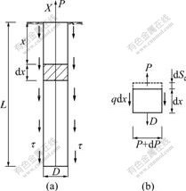
Fig.2 Load transfer mechanism of tension pile: (a) Total distribution of stresses; (b) Element stresses
According to the balance of an infinitesimal element of the uplift pile in Fig.2, the following formula is established:
![]() (7)
(7)
where q is the even shear in each unit area. According to Hooke��s law, the relationship between elastic deformation of and the axis pressure of P is
![]() (8)
(8)
Combining Eqns.(7) with (8), q can be expressed as
![]() (9)
(9)
According to assumption 3) in Section 2.1, we can have
q=��D��=GsSs (10)
where �� and Gs are the shear stress on the uplift pile and the shear modulus of the soil, respectively. Combining Eqn.(9) with Eqn.(10), the differential function of elastic displacement can be expressed as
![]() (11)
(11)
Similarly, combining Eqn.(9) with Eqn.(10) and ignoring the higher-order terms, the differential function of shear displacement is expressed as
![]() (12)
(12)
According to the boundary conditions of ![]() and
and ![]() and the expression of ��=
and the expression of ��=![]() (�� is the Poisson ratio), the shear displacement of Ss(x) and the friction force of ��(x) along the uplift pile can be expressed as
(�� is the Poisson ratio), the shear displacement of Ss(x) and the friction force of ��(x) along the uplift pile can be expressed as
![]() (13)
(13)
![]() (14)
(14)
If order x=0 and x=L, the displacements of up and bottom pile are respectively
![]() (15)
(15)
![]() (16)
(16)
Combining Eqn.(15) with Eqn.(16), the relationship between the bottom displacement and the up displacement can be obtained.
S(0)=S(L)cosh(��L) (17)
Similarly, combining Eqns.(1) with (16), we can have
![]() (18)
(18)
So the ultimate displacement of uplift pile can be expressed as
![]() (19)
(19)
It can be seen from Eqn.(19) that the displacement can be calculated if the material parameters of the uplift pile, the geometry of the uplift pile and the parameters of the soil are known. Furthermore, the shear resistance and the shear displacement between pile and soil are related to the diameter and length of the pile, the ratio of length to diameter of the pile, the elastic modulus of the pile and the characteristic of the soil.
3 Discussion and comparison with measured data
3.1 Discussion
In order to investigate the distribution character of friction resistance and the shear displacement along the pile length, the numerical simulation was adopted here. The parameters for numerical simulation were as follows: Ea=110 GPa, L=6.0 m, D=0.5 m, P=350 kN. Figs.3 and 4 show the friction resistance and the shear displacement along the pile length with different shear moduli, respectively.
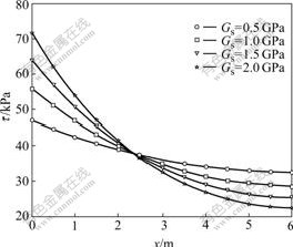
Fig.3 Distribution of friction resistance along pile length
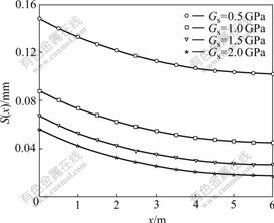
Fig.4 Distribution of shear displacement along pile length
From Fig.3, it can be seen that the friction resistance attenuates from the top to the bottom of the pile with non-linearity. The maximum and minimum friction resistances appear at the top and the bottom of the pile, respectively. The larger the shear modulus, the more the nonlinearity. If the shear modulus exceeds a certain value, the shear resistance will be centralized on the 2/3 of pile length. These results correspond to the fact that friction resistance is fully exerted for piles in rock masses, and that the shear resistance is concentrated on top and the shear resistance is distributed uniformly for piles in soft soils.
From Fig.4, it is found that the shear displacement distribution is similar to the friction resistance distribution. The effect of shear modulus on the shear displacement is smaller than that on the friction resistance. At the same time, it can be seen that the shear displacement only offers a little to the whole displacement in the 1/3 length at the bottom of pile. This theoretical conclusion agrees with the field monitoring data obtained in Ref.[1].
3.2 Comparison with measured data
In order to validate the reliability of the above method, a model and a pier uplift pile test data were taken as examples for comparison.
For the model test pier pile, the model parameters were as follows: L=4.5 m, D=0.18 m, Ea=110 GPa, Gs= 2.179 MPa, ��=0.18. The grade loading was adopted. The maximum loading was 32 kN. The relationship between the top pile settlement S and the uplift force Q is shown in Fig.5. The theoretic value S=12.044 mm is more nearly to the test data of S=12.216 mm.
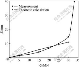
Fig.5 Q��S curves of model tension pile
For the pier uplift pile, the maximum pullout force is 18 MN. The parameters were as follows: L=10.0 m, D=1.5 m, Ea=100 GPa, Gs=4.7 MPa, ��=0.245. The com- parison between the theoretic values in this work and the test data is shown in Fig.6. The theoretic value S=0.391 mm is more nearly to the test data of S=0.398 mm.
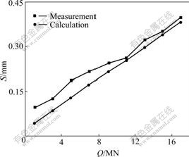
Fig.6 Q��S curves of pier uplift pile
From the comparison between the theoretic values in this work and the test data, it can be seen that the present results obtained with this method agree with the monitoring data favorably, with the average difference being less than 12%. The comparison proves the theoretic reliability and validity presented in this work, so it can provide consult for uplift pile design. The causation of errors between the theoretical calculation and the monitoring data come from other factors such as the pile length, the pile diameter, the strength of the soil around the pile and so forth[12-15]. The effects of these influencing factors on the displacement and deformation of uplift pile demand more study.
4 Conclusions
1) The distribution of the friction resistance is nonlinear for the uplift pile. Rational calculation method is presented for calculating the deformation, ultimate displacement and shear resistance of the uplift pile embedded in rock and soil. The interaction behavior between the pile and soil mass is described by shear modulus, which is determined by the interaction medium between the pile and the soil.
2) The maximum and minimum friction resistances appear at the top and the bottom of the pile, respectively. If the shear modulus exceeds a certain value, the friction resistance will be centralized on the 2/3 of pile length. The results of theoretical solutions and those of tests show generally favorable agreement, which proves that the present method is reasonable for uplift designs.
References[1] HUANG Feng, LI Guang-xin, LU He. Analysis of deformation of tension in sand soil [J]. China Civil Engineering Journal, 1999, 32(2): 31-36. (in Chinese)
[2] LEHANE B M, JARDINE R J, BOND A J, FRAND R. Mechanisms of friction in sand from instrumented pile tests [J]. Journal of Geotechnical Engineering, 1993, 119(1): 19-35.
[3] CAIRO ��, CONTE ��. Settlement analysis of pile groups in layered soils [J]. Canadian Geotechnical Journal, 2006, 43(8): 788-801.
[4] ZHANG C, YIN J. Field static load tests on drilled shaft founded on or socketed into rock [J]. Canadian Geotechnical Journal, 2000, 37(5): 1283-1294.
[5] SERRANO A, OLALLA C. Tensile resistance of rock anchors [J]. International Journal of Rock Mechanics and Mining Sciences, 1999, 36(3): 449-474.
[6] HOEK E, BROWN E T. Practical estimates of rock masses strength [J]. International Journal of Rock Mechanics and Mining Sciences, 1997, 34(7): 1165-1186.
[7] YANG Xiao-li, YIN Jian-hua. Slope stability analysis with nonlinear failure criterion [J]. Journal of Engineering Mechanics, 2004, 130(3): 267-273.
[8] YANG Xiao-li, LI Liang, YIN Jian-hua. Seismic and static stability analysis for rock slopes by a kinematical approach [J]. Geotechnique, 2004, 54(8): 543-549.
[9] YANG Xiao-li, LI Liang, YIN Jian-hua. Stability analysis of rock slopes with a modified Hoek-Brown failure criterion [J]. International Journal for Numerical and Analytical Methods in Geomechanics, 2004, 28(2): 181-190.
[10] EMMETT K. Pile disturbance in layered ground [J]. Ground Engineering, 2005, 38(12): 30-32.
[11] WANG Tao, LIU Jin-li. Tests on influence of pile-soil-pile interaction [J]. Chinese Journal of Geotechnical Engineering, 2008, 30(1): 100-105. (in Chinese)
[12] ZHAO P, JI S. Refinement of shear-lag model and its application [J]. Tectonophisics, 1997, 279(1): 37-53.
[13] YANG Xiao-li. Seismic displacement of rock slopes with nonlinear Hoek-Brown failure criterion [J]. International Journal of Rock Mechanics and Mining Sciences, 2007, 44(6): 948-953.
[14] ABRAMENTO M, WHITTLE J A. Analysis of pullout tests for planar reinforcements in soil [J]. Journal of Geotechnical Engineering, 1995, 121(6): 476-485.
[15] LEE K M, XIAO Z R. A simplified nonlinear approach for pile group settlement analysis in multilayered soils [J]. Canadian Geotechnical Journal, 2001, 38(5): 1063-1080.
Foundation item: Project(05-0686) supported by the Program for New Century Excellent Talents in University; Project(200550) supported by the Foundation for the Author of National Excellent Doctoral Dissertation of China
Received date: 2008-01-08; Accepted date: 2008-04-20
Corresponding author: YANG Xiao-li, Professor; Tel: +86-731-2656248; E-mail: yxnc@yahoo.com.cn
(Edited by CHEN Wei-ping)
Abstract: On the assumptions that the shear resistance increases linearly with increasing shear displacement between the uplift pile and surrounding soil, that the axis force is distributed as parabola along the pile length, that elastic distortion occurs when the pile is loaded, that the displacement of pile is in accord with that of the soil, and that the uplift pile failure is regarded as the soil failure, a rational calculation method was proposed for calculating the deformation, ultimate displacement and shear resistance of piles. The distributions of frictional resistance and the shear displacement along the pile length were obtained with the method. The comparisons were made between the measurement results and the present results. The present theoretical results agree well with the measurement results, with the average difference being less than 12% before failure. The comparisons show that the proposed method is reasonable for uplift design and engineering construction of piles.
