
Trans. Nonferrous Met. Soc. China 31(2021) 1074-1086
Synthesis and properties of single-crystal Ni-rich cathode materials in Li-ion batteries
Shi-jie LU1,2,3, Yang LIU1,2,3, Zhen-jiang HE1,2,3, Yun-jiao LI1,2,3, Jun-chao ZHENG1,2,3, Jing MAO4, Ke-hua DAI5
1. School of Metallurgy and Environment, Central South University, Changsha 410083, China;
2. National Engineering Laboratory for High Efficiency Recovery of Refractory Nonferrous Metals, Central South University, Changsha 410083, China;
3. Engineering Research Center of the Ministry of Education for Advanced Battery Materials, Central South University, Changsha 410083, China;
4. School of Materials Science and Engineering, Zhengzhou University, Zhengzhou 450001, China;
5. College of Chemistry, Tianjin Normal University, Tianjin 300387, China
Received 15 April 2020; accepted 29 December 2020
Abstract:
Single-crystal Ni-rich cathode material LiNi0.88Co0.09Al0.03O2 (SC) was synthesized by a high-temperature solid-state calcination method. Physicochemical properties of primary and delithiated SC samples were investigated by X-ray diffractometry, X-ray photoelectron spectroscopy, and transmission electron microscopy. Electrochemical performance was characterized by long-term cycling, cyclic voltammetry, and in-situ impedance spectroscopy. The results indicated that high temperature rendered layered oxides to lose lithium/oxygen in the interior and exterior, and induced cationic disordering. Besides, the solid-phase synthesis process promoted phase transformation for electrode materials, causing the coexisting multi-phase in a single particle. High temperature can foster the growth of single particles, but it caused unstable structure of layered phase.
Key words:
lithium-ion battery; cathode material; single-crystal; electrochemical performance; phase transformation;
1 Introduction
Li-ion battery (LIB) has been one of the most promising energy storage devices in recent years. The development of LIB attracted great attention worldwide because its emergence has exerted a strong influence on every aspect of people��s daily lives. Three distinguished scientists were awarded the Nobel Prize for their outstanding contributions to LIBs last year. With great expectations for better energy storage devices, people turn the spotlight on the development of LIBs again.
Cathode materials are considered as one of the bottlenecks for the development of LIBs. Currently, the cathode materials including LiFePO4, LiMn2O4, LiNi1-x-yCoxMnyO2 (NCM), and LiNi1-x-yCoxAlyO2 (NCA) are used for commercial LIBs. LiFeO4 is one of the most successful cathode materials due to its safety and cycling stability, but the relatively low energy density limits its extensive application. Although LiMn2O4 is low-cost, the capacity of it decays fast.
Ni-rich NCA or NCM materials with a high theoretical capacity of 275 mA��h/g are accepted as the most promising candidate to meet increasing energy requirements. However, many investigations demonstrated that the thermal stability and cycling performance will get worse with the gradually increasing Ni proportion of Ni-rich materials [1-3].
For Ni-rich NCA or NCM materials, phase transformation (H2-H3) results in internal microcracks due to anisotropic lattice volume change during the lithium ion insertion/extraction process, further inducing fast capacity fading [4-6]. Some researchers suggested that element doping or surface coating can relieve anisotropic lattice volume change to prevent Ni-rich from capacity fading, but it is hard to avoid structural collapse by those methods because conventional NCM or NCA is usually polycrystal spherical particles composed of primary particles [7,8].
By inspiration of successful product LiCoO2, NCA or NCM may also be designed as single- crystal. Recently, LI et al [9] have shown that single-crystal LiNi0.5Mn0.3Co0.2O2 has better capacity retention than polycrystal. Some related researches confirmed that single-crystal performed better thermal stability and stronger resistance to oxygen loss. KIMIJIMA et al [10] synthesized single-crystal NCM111 by using a molten salt method. KIM [11] also applied a similar method to synthesize single-crystal NCM811.
Single-crystal Ni-rich layered oxides have attracted much attention of researchers. The changes in the crystal structure and electrochemical performance are unclear due to temperature sensitivity. Therefore, in this study, single-crystal Ni-rich cathode material LiNi0.88Co0.09Al0.03O2 (SC) was synthesized by a high-temperature solid-state calcination method. Physicochemical properties of primary and delithiated SC samples were studied by X-ray diffractometry, X-ray photoelectron spectroscopy, transmission electron microscopy. Electrochemical performance was characterized by long-term cycling, cyclic voltammetry, and in-situ impedance spectroscopy. The structural parameters and phase composition induced by the synthesis process were also investigated.
2 Experimental
2.1 Reagents
The reagents in this research contain nickel (II) sulfate hyxahydrate (NiSO4��6H2O, 99.9%, Aladdin), manganese sulfate tetrahydrate (MnSO4��4H2O, 99.99%, Aladdin), aluminum sulfate octadecahydrate (Al2(SO4)3��18H2O, 99.95%, Aladdin), sodium hydroxide (NaOH, 98%, Aladdin), ammonium hydroxide solution (NH3��H2O, 28%, Aladdin), lithium hydroxide monohydrate (LiOH��H2O, 98%, Aladdin). Metal hydroxide precursors Ni0.88Co0.09Al0.03(OH)2 were obtained by co-precipitation in a continually stirred tank reactor (CSTR). More preparation details of precursors referred to Ref. [12].
2.2 Synthesis of single-crystal LiNi0.88Co0.09- Al0.03O2
The precursor Ni0.88Co0.09Al0.03(OH)2 was mixed with LiOH��H2O (1:0.9, molar ratio) and calcined at 480 ��C for 3 h, and planetarily ball- milled for 30 min in stainless steel jars, and calcined at 480 ��C for 2 h and at 900 ��C for 3 h. Then, it was mixed with extra LiOH��H2O (the total molar ratio of first precursor to LiOH��H2O was 1.05:1) and calcined at 730 ��C for 9 h. Single- crystal was finally obtained (marked as SC).
2.3 Synthesis of polycrystalline LiNi0.88Co0.09- Al0.03O2
The precursor Ni0.88Co0.09Al0.03(OH)2 was mixed with LiOH��H2O (1:1.02, molar ratio), then calcined at 480 ��C for 5 h and at 730 ��C for 12 h. Polycrystalline was obtained (marked as PC). All heating and cooling were conducted under a controlled rate of 10 ��C/min.
2.4 Materials characterization
The scanning electron microscopy (SEM) images were collected to observe the morphologies and structures of samples using JEOL (JSM-5612 LV) with an accelerating voltage of 20 kV. The XRD patterns with the 2�� range of 10��-90�� were collected using Rigaku (Rint-2000) with Cu ���� radiation to identify the crystalline structure of the prepared samples. These XRD data were analyzed via Rietveld refinement using the program PC-GSAS. The X-ray photoelectron spectra (XPS) were collected using Perkin-Elmer (PHI 5600) to confirm the main elements�� state and impurity composition on the surface of materials. Transmission electron microscopy (TEM) and electron diffraction patterns were obtained by using a Titan G260-300 microscope.
2.5 Electrochemical methods
The details of positive electrode fabrication and electrochemical measurements have been reported in Ref. [13].
3 Results and discussion
3.1 Physical chemistry characteristics
The XRD and Rietveld refinement patterns of SC and PC are shown in Fig. 1. Figures 1(c, d, g, h) show expanded views of the (104) and (108)/(110) Bragg peaks. The black cross marks represent the measured diffraction data. The red line is the calculated pattern from refinement results. The blue line shows the differences between measured data and calculated data. The green perpendicular line marks out the Bragg peak position. The XRD patterns of both samples are assigned to a hexagonal ��-NaFeO 2 structure (space group R3m). Some parameters of the crystal structure are shown in Table 1. Because the radius of Ni2+ ions (0.69  ) is similar to that of Li+ ions (0.76 ), Ni2+ ions often tend to migrate into the lithium layer (also called cation disorder). The larger lattice parameters a, c, and the unit cell volume for SC are attributed to the presence of more Ni2+ ions in the lithium layer [14]. No impurities are found for both samples in Figs. 1(b) and (f). Figures 1(c) and (g) show that the division degree of (104) peak of SC is slightly smaller than that of PC. Figures 1(d) and (h) show that more obvious peak splitting of (108)/(110) for PC is observed, compared with that of SC. These two characteristics indicate that the PC has a better crystallinity and a more stable layer structure. Besides this, no significant differences are found between SC and PC, suggesting that the crystal structure of SC is good as well according to XRD pattern analysis.
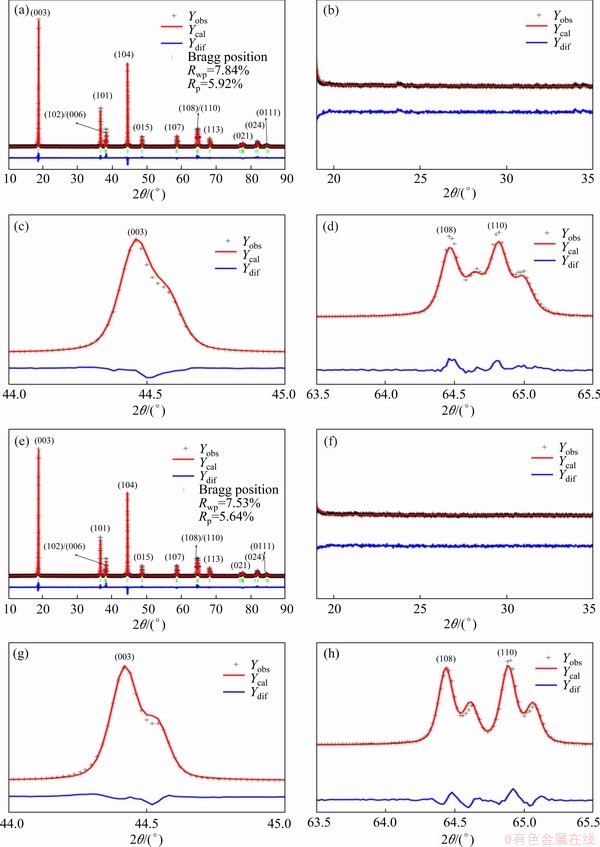
Fig. 1 Rietveld refinement results of X-ray diffraction patterns of SC (a) and PC (e), enlarged XRD pattern of SC (b, c, d) and PC (f, g, h) from 19�� to 35��, from 44�� to 45��, and from 63.5�� to 65.5��, respectively (Rwp is weighted profile R-factor and Rp is profile residual)
The morphologies of precursors, SC, and PC are shown in Figs. 2(a, d), (b, e), and (c, f), respectively. Precursors with sizes of 10-15 ��m were made by using the co-precipitation method. The spherical polycrystalline of precursors was composed of fine primary crystal plates. Understanding the intrinsic physicochemical properties of inorganic materials is essential for crystal growth in lithium-ion battery research. Extensive research has indicated that energy and molten-salt are indispensable for stimulating rapid growth of the salt crystals [10,15]. In the presence of excess lithium and high temperature, the well-defined single crystal material with particle size of 2-4 ��m was synthesized, as shown in Figs. 2(b) and (e). However, the particles with nonuniform sizes were randomly distributed from observation in the images. Figures 2(c) and (f) exhibit normal agglomerates with sizes of 100-200 nm secondary particles. Some white spots in the images marked by red circles may be lithium salt.
Table 1 Rietveld refinement results of SC and PC cathode materials (a and c are lattice parameters of a- and c-axis, respectively, Zox is atomic coordinate for oxygen ions, V is unit cell volume, S is goodness of fitting parameter of Rwp/Rp)
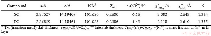
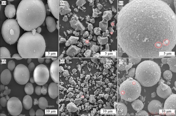
Fig. 2 SEM images of precursors (a, d), SC (b, e) and PC (c, f) samples
The XPS spectra of single crystal and polycrystalline were acquired to obtain the physicochemical information on the surface. Figure 3(a) shows that two adventitious carbon signals dominated the C 1s region at 248.82 and 288.50 eV. The sub-peak at 289.84 eV was assigned to MCO3 (M=metal ions). This impurity composite is considered to be associated with carbon dioxide in the air. The Ni spectra are shown in Fig. 3(b). The binding energies for Ni2+ and Ni3+ appeared at 854.40 and 855.80 eV, respectively. The other two sub-peaks were assigned to satellite peaks of Ni3+ and Ni2+. For Ni-rich materials, the Ni element is the main contributor during electro- chemical oxidation-reduction processes. Therefore, investigating the valence state and content of the Ni element is necessary to elucidate electrochemical performance better and evaluate synthesis strategy [16]. The Ni 2p3/2 peak at 855.40 eV of SC is lower than that of PC, indicating fewer nickel-oxygen covalences for the SC sample. The percentage of Ni2+ for SC is higher than that of Ni2+ for PC. The higher percentage of Ni2+ on the surface implied more oxygen vacancies, suggesting the microscopic oxygen loss process. The formation of more Li2CO3 and higher cation disorders were observed due to the exposure to air, as confirmed by those XRD refinement results. The O 1s region is shown in Fig. 3(c). The peaks of lattice oxygen and surface oxygen for SC and PC appeared at 531.80 eV and ~529.20 eV, respectively. This sub-peak (~529.20 eV) may also be representative of metal oxides which are not associated with lattice oxygen, as it leads to an increase of the impurity phase on primary particles. The second sub-peak at 531.40 eV could be identified as metal carbonate (namely Li2CO3), which agrees with the conclusion based on the C 1s spectra. The third sub-peak at 531.80 eV with the largest contribution is assigned to lithium hydroxide. According to the peak area ratio of Li2CO3/LiOH, the residual soluble base content of SC sample was more than that of PC sample, hinting at the Li loss from the oxides and formation of Li2CO3 on the surface. Longer grinding and calcination time may result in more active reactions with air, further yielding a bad influence on its electrochemical performance.
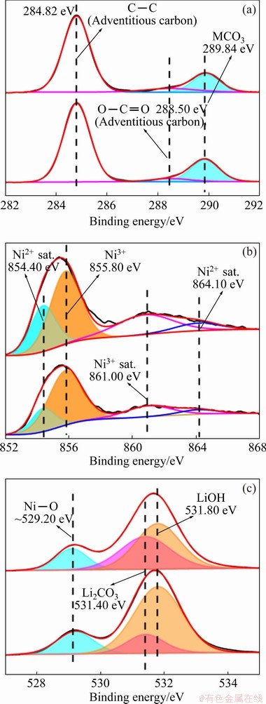
Fig. 3 XPS spectra of C 1s (a), Ni 2p (b) and O 1s (c) for SC and PC samples
3.2 Electrochemical performance
Although the structure and morphology of SC were exhibited in detail, good electrochemical performance is the most critical indicator for good single crystal. The first three cyclic voltammetry (CV) curves for SC and PC were plotted for better understanding of the structural changes and electrochemical mechanism occurring during Li+ insertion/extraction (Figs. 4(a) and (b)). Like LiNiO2, the PC underwent a series of phase transitions while the SC did not experience any relevant transitions upon charge/discharge processes. These transitions contain hexagonal to monoclinic (H1��M), monoclinic to hexagonal (M��H2), and hexagonal to hexagonal (H2��H3) [15,17,18]. The last phase transition (H2��H3) has been considered to result in unit cell volume contraction due to severe lattice distortion. The two peaks between 4.05 and 4.20 V were hardly observed for the SC. It is generally accepted that each phase transition indicates Li+ insertion/ extraction associated with a more accessible capacity [19]. In other words, the disappearance of those two peaks means that a part of Li+ ions could not be extracted from the SC. This phenomenon might be caused by the thermal-induced phase transformation, which needs further experimental verification for the prepared SC. Besides, a larger voltage gap (��V=0.404 V) between the first pair of redox peaks of the SC than that (��V=0.363 V) of the PC was observed in Figs. 4(a) and (b). This indicates that the SC has inferior reversibility of Li+ insertion/extraction and higher polarization degree. The increased polarization is attributed to the longer lithium diffusion length among particles. The charge/ discharge voltage profiles of both SC and PC are shown in Figs. 4(c) and (d), respectively. Compared with PC, the SC has dramatically faster voltage decay. As charge/discharge proceeded, those plateaus in the high-voltage regions began to disappear gradually. The cycling performances of SC and PC were tested at 1C rate over a voltage range of 2.75-4.3 V (vs Li+/Li) (1C=180 mA��h/g). As shown in Figs. 4(e) and (f), an initial discharge capacity of 166.4 mA��h/g was achieved by the prepared SC, accompanying coulombic efficiency (CE) of 71.42%. However, the PC possessed an initial capacity of 185.8 mA��h/g with CE of 84.95%. After 200 cycles, the SC only retained 64.18% of the initial capacity while the PC still had 87.56% capacity retention. During 100 cycles, mid-voltage for SC decayed faster than that of PC material. In contrast to the expected results, the SC sample prepared by the method in this work showed poor electrochemical performance. However, a series of experiments were still conducted to investigate why SC had poorer electrochemical performance than PC deeply.
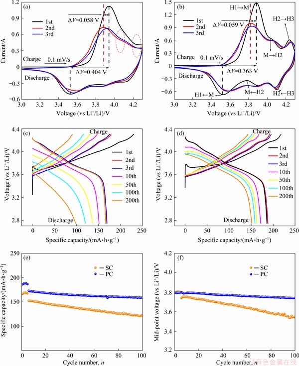
Fig. 4 First three cyclic voltammetry (CV) curves of SC (a) and PC (b) cathodes at scanning rate of 0.1 mV/s, electrochemical charge/discharge curves of SC (c) and PC (d) at 1C rate (1C=180 mA��h/g), cycling performance (e) and mid-point voltage performance (f) of SC and PC
Figures 5(a) and (b) depict the change of Nyquist impedance during the charge and discharge processes for SC, respectively. To better explain what happened in these processes, some theories were cited to clarify the Nyquist impedance of a porous electrode [20]. Usually, four parts constitute the total impedance of electrode, including (I) in high-frequency region, resistance from ions passing through the separator and from electrons transfer due to external cell contact; (II) the contact resistance between active materials and the current collector; (III) the medium frequency resistance from the charge transfer, the interfacial double-layer capacitance of electrode, the electrons and ions moving in the electrode; (IV) a Warburg diffusion resistance in the low-frequency range. Figure 5(a) shows only one semi-circle at low voltage and two semi-circles at high voltage. RADIN et al [21] argued that lithium diffusion is very difficult inside the cathode due to the absence of vacancy numbers at the low charging state. The strong CV peaks of cells at about 3.94 V and 4.20 V indicated that lithium diffusion was quite slow at both low and high states of charge.
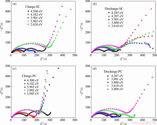
Fig. 5 Nyquist impedance during charge (a, c) and discharge (b, d) processes for SC (a, b) and PC (c, d)
According to the electrochemical impedance principle, the semi-circle in high frequency is usually defined as the interfacial film resistance (collection term Rsl) including the above (I) and (II) parts. Medium frequency semi-circle corresponds to the charge transfer resistance (Rct) [22]. The low frequency line is associated with the Warburg impedance. As the potential increases to 3.8 V (vs Li+/Li), the interfacial resistance tends to appear. At the first charge process, the electrolyte and electrode have an interfacial chemical reaction. Then, as the voltage increases, the interface between cathode and electrolyte gradually involves chemical and electrochemical reactions [23,24]. Under the collective interaction from interfacial reaction and lithium diffusion in different states of charge, the Rct changes vastly while Rsl keeps nearly constant.
The mechanism of Li+ intercalation is formally similar to the hydrogen direct absorption reaction [25]. The charge transfer resistance depends strongly on the state of charge. The Rsl semi-circles are hardly observed before 3.8 V (vs Li+/Li), which is attributed to the absence of interfacial film under the low voltage. The Rct semi-circle increases just slightly in the voltage range of 3.8-4.2 V (vs Li+/Li) due to the facile charge transfer kinetics. At the voltage of 4.3 V, the Rct impedance starts sharply growing because of the surface reconstruction induced by the high voltage [26]. During the discharge process, the interfacial resistance remains unchanged while the charge transfer resistance initially decreases and then increases. Charge transfer resistance performs a little complicated relationship with the state of charge. This suggests that electrochemical reaction renders electrode materials to perform the structural and chemical changes, which provides extra barriers for Li+ diffusion.
Furthermore, it might speculate that the combination of the solid-state electrolyte interface (SEI) and rock-salt layer dominates the unusual change of the third part. It is expected that lithium diffusion and charge transfer are different at the interface between the electrolyte and SEI layer, SEI layer and rock-salt layer, rock-salt layer and the bulk. Because the ionic conductivity is proportional to the carrier concentration multiplied by carrier mobility [27], the rock-salt layer has low Li+ diffusion due to its low lithium content, further altering the charge transfer resistance. Consequently, it could explain why the resistance of the third part is big at both low and high voltages, which is corresponding to the phenomenon experimentally observed.
The impedance spectra for PC materials during the first charge and discharge processes are shown in Figs. 5(c) and (d), respectively. According to the theoretical foundation of impedance spectroscopy, the Rct of PC materials is more than that of SC materials. The Rsl is hardly observed in the low state of charge, while Rsl is very obvious in the high state of charge. This phenomenon is attributed to the secondary aggregation structure, which provides a lower specific surface area and slower charge transportability [28]. On the other hand, when one is much larger than the other, two semi-circles of the Rsl and Rct will merge.
3.3 Crystal structure of delithiated samples
Although the prepared SC is not as good as expected, further experiments can help researchers have a better understanding of single crystals. First of all, the morphologies and structure characteristics of delithiated materials were reported to help explain why SC failed. Figures 6(a-c) show the XRD full pattern, XRD patterns of amplified (003) peak and (104) peak of SC and PC charged to 4.3 V, respectively. From the observation in Fig. 6(a), the delithiated materials of both samples can still keep layer structure, but positions of some peaks shift. The shifts of the (003) reflection for both samples are attributed to the generation of H2 phase during the charge process. However, this reflection can be deconvoluted for two phases according to the relative peak intensities of H2 and H3 phases [17], whereas both retain a substantial fraction of H2 phase. In particular, (108) and (110) peaks indicate the change of the lattice constants a and c, respectively. (108) peak tends to be weak, suggesting the unstable layered structure. (110) peak shifts to a high-angle position, suggesting the decreased lattice constants a and c. As indicated in these patterns, no significant difference for both delithiated SC and PC is observed, which means that it needs further microscopic characterization.
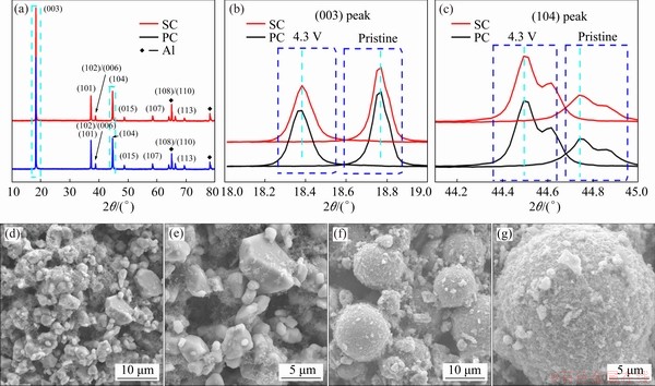
Fig. 6 XRD patterns during first cycle attest to structural stability of SC and PC at first-charge state (4.3 V) cathode (a), enlarged XRD patterns from 18�� to 19�� (b) and 44.1�� to 45�� (c), and SEM images of delithiated SC (d, e) and PC (f, g) samples
Figures 6(d-g) show the SEM images of SC and PC after being charged to 4.3 V. The materials are in the delithiation state when they are charged to 4.3 V. Compared with the pristine for SC and PC, these delithiated materials have more granules. The strain generated on the surface of these particles is higher than that of the bulk, often triggering some potential micro-cracks. Strain and tension most likely cause the agglomerates to dissociate. Figures 6(e) and (g) show images with low magnification capturing as many changes as impossible on the surface. The surfaces of both delithiated materials are wrapped by blurred materials, including acetylene black and binder, but no micro-cracks are observed.
3.4 Phase composition of samples
The phase evolution of the randomly selected particle for SC is shown in Fig. 7(a). The diffraction spots observed at the edge of the selected particle came from the layered (Z.A.=[001]L) and spinel structures (Z.A.=[111]S), corresponding to the schematically illustrations in Figs. 7(b) and (c), respectively. The rock-salt structure (Z.A.=  RS) (Fig. 7(d)) was also observed in some specific edge areas. A CdI2-like structure formed or the migration from transition metals to the Li layer or the disorder of lithium ions and vacancies yielded those forbidden spots in the delithiation process [29-31]. By the observations from diffraction patterns (Figs. 7(e-l)), the spots from the spinel phase at the edge are more obvious than those in the center, indicating that the degradation at the edge is severer than that inside. According to some related reports, this phenomenon is attributed to several factors such as preferred directions of Li+ diffusion or electrolyte wetting between the electrode and conductive materials [32-34]. The poor electrochemical performance was explained by structure degradation. The degradation was caused by the migration of transition metals (mainly Ni) to octahedral sites. And Ni cations with high oxidation states generated stronger electrostatic attraction. Consequently, the Li+ diffusion channels are contracted so that it is difficult for Li+ insertion/extraction. The phase transformation involves Li/O loss and the merger of the adjacent TMO6 layers caused by the similarity of these two structures [35].
For PC material, the high-resolution TEM (HRTEM) image in the randomly selected particle was collected, and several areas from the edge to the center were selected to perform fast Fourier transform (FFT) to observe phase change (Fig. 8).
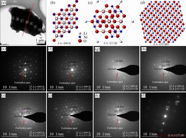
Fig. 7 Bright field TEM image for randomly selected particle of SC cathode (a), schematically illustrated diffraction patterns for layered (Z.A.=[001]L) (b), spinel (Z.A.=[111]S) (c), and rack-salt (Z.A.=RS) structure (d), series of selected area electron diffraction (SAED) patterns of selected particle from edge to center, and to edge for SC cathode (e-l) (Red spots indicate region with additional forbidden spots)
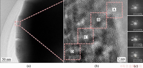
Fig. 8 TEM images (a, b) and fast Fourier transformation (FFT) patterns (c) of several regions (A, B, C and D) from surface to interior collected to analyze crystal structure change for PC material
The only spots from the layered structure  zone were observed at the edge of the PC [36]. For the interior, the spots from the layer phase and spinel phase coexisted. Under the high voltage condition, the PC material also performed phase transformation, but the surface still kept layer structure, which could prevent electrolyte into the interior. Besides, this research indicated that the crystal structures of Ni-rich materials changed from layer to spinel, then to rock-salt, and back to layer during the synthesis process. Thus, phase transformation is a normal phenomenon for SC and PC, but the reversible phase change is vital for better electrochemical performance.
4 Conclusions
(1) Single-crystal LiNi0.88Co0.09Al0.03O2 was synthesized by using the conventional solid-state calcination method, the electrochemical performance of which was inferior to that of PC material, indicating that this SC is a flawed cathode.
(2) Single-crystal Ni-rich oxides synthesized under high temperature performed cationic disordering and lithium/oxygen loss from the layered structure.
(3) The thermo-induced structural evolution within single-crystal particles revealed that synthesis process speeded up transformation and caused the existence of multiphase in single particles.
(4) Temperature could supply energy to foster the growth of primary particles, but it caused damage to the stable layered structure. Ni-rich layered oxides need a moderate temperature to synthesize single-crystal materials.
Acknowledgments
The authors are grateful for the financial supports from the National Natural Science Foundation of China (51974368) and the Fundamental Research Funds of the Central South University, China.
References
[1] NOH H, YOUN S, YOON C S, SUN Y. Comparison of the structural and electrochemical properties of layered Li[NixCoyMnz]O2 (x=1/3, 0.5, 0.6, 0.7, 0.8 and 0.85) cathode material for lithium-ion batteries [J]. Journal of Power Sources, 2013, 233: 121-123.
[2] YOON C S, CHOI M H, LIM B, LEE E, SUN Y. Review�� High-capacity Li[Ni1-xCox/2Mnx/2]O2 (x=0.1, 0.05, 0) cathodes for next-generation Li-ion battery [J]. Journal of the Electrochemical Society A, 2015, 162: 2483-2489.
[3] RYU H, PARK K, YOON C S, SUN Y. Capacity fading of Ni-rich Li[NixCoyMn1�Cx�Cy]O2 (0.6��x��0.95) cathodes for high-energy-density lithium-ion batteries: Bulk or surface degradation? [J]. Chemistry of Materials, 2018, 30: 1155-1163.
[4] KONDRAKOV A O, SCHMIDT A, XU J, GE��WEIN H, MONIG R, HARTMANN P, SOMMER H, BREZESINSKI T, JANEK J. Anisotropic lattice strain and mechanical degradation of high- and low-nickel NCM cathode materials for Li-ion batteries [J]. Journal Physical Chemistry C, 2017, 121: 3286-3294.
[5] YOON C S, JUN D, MYUNG S, SUN Y. Structural stability of LiNiO2 cycled above 4.2 V [J]. ACS Energy Letters, 2017, 2: 1150-1155.
[6] YOON C S, RYU H, PARK G T, KIM J, KIM K, SUN Y. Extracting maximum capacity from Ni-rich Li[Ni0.95Co0.025Mn0.025]O2 cathodes for high-energy-density lithium-ion batteries [J]. Journal of Material Chemistry A, 2018, 6: 4126-4132.
[7] XIE Q, LI W D, MANTHIRAM A. A Mg-doped high-nickel layered oxide cathode enabling safer, high-energy-density Li-ion batteries [J]. Chemistry of Materials, 2019, 31: 938-946.
[8] ZHENG Jun-chao, YANG Zhuo, HE Zhen-jiang, TONG Hui, YU Wan-jing, ZHANG Jia-feng. In situ formed LiNi0.8Co0.15Al0.05O2@Li4SiO4 composite cathode material with high rate capability and long cycling stability for lithium-ion batteries [J]. Nano Energy, 2018, 53: 613-621.
[9] LI J, CAMERON A R, LI H Y, GLAZIER S, XIONG D J, CHATZIDAKIS M, ALLEN J, BOTTON G A, DAHN J R. Comparison of single crystal and polycrystalline LiNi0.5Mn0.3Co0.2O2 positive electrode materials for high voltage Li-ion cells [J]. Journal of the Electrochemical Society A, 2017, 164: 1534-1544.
[10] KIMIJIMA T, ZETTSU N, TESHIMA K. Growth manner of octahedral-shaped Li(Ni1/3Co1/3Mn1/3)O2 single crystals in molten Na2SO4 [J]. Crystal Growth & Design, 2016, 16: 2618-2623.
[11] KIM Y. Lithium nickel cobalt manganese oxide synthesized using alkali chloride flux: Morphology and performance as a cathode material for lithium ion batteries [J]. ACS Applied Material Interfaces, 2012, 4: 2329-2333.
[12] ANDREW V B, DAHN J R. Analysis of the growth mechanism of coprecipitated spherical and dense nickel, manganese, and cobalt-containing hydroxides in the presence of aqueous ammonia [J]. Chemistry of Materials, 2009, 21: 1500-1503.
[13] ZHENG J C, YANG Z, DAI A, TANG L B, WEI H X, LI Y J, HE Z J, LU J. Boosting cell performance of LiNi0.8Co0.15Al0.05O2 via surface structure design [J]. Small, 2019, 15: 1904854.
[14] LIU Yang, TANG Lin-bo, WEI Han-xin, ZHANG Xia-hui, HE Zhen-jiang, LI Yun-jiao, ZHENG Jun-chao. Enhancement on structural stability of Ni-rich cathode materials by in-situ fabricating dual-modified layer for lithium-ion batteries [J]. Nano Energy, 2019: 65: 104043.
[15] KIM J, RYU H, KIM S J, YOON C S, SUN Y. Degradation mechanism of highly Ni-rich Li[NixCoyMn1�Cx�Cy]O2 cathodes with x>0.9 [J]. ACS Applied Material Interfaces, 2019, 11: 30936-30942.
[16] YANG Shu-qi, WANG Peng-bo, WEI Han-xin, TANG Lin-bo, ZHANG Xia-hui, HE Zhen-jiang, LI Yun-jiao, TONG Hui, ZHENG Jun-chao. Li4V2Mn(PO4)4-stablized Li[Li0.2Mn0.54Ni0.13Co0.13]O2 cathode materials for lithium ion batteries [J]. Nano Energy, 2019, 63: 103889.
[17] LI W, REIMERS J N, DAHN J R. In situ X-ray diffraction and electrochemical studies of Li1-xNiO2 [J]. Solid State Ionics, 1993, 67: 123-130.
[18] OHZUKU T, UEDA A, NAGAYAMA M. Electrochemistry and structural chemistry of LiNiO2  for 4 volt secondary lithium cells [J]. Journal of the Electrochemical Society, 1993, 140: 1862-1870.
[19] LI H Y, LIU A, ZHANG N, WANG Y Q, YIN S, WU H H, DAHN J R. An unavoidable challenge for Ni-rich positive electrode materials for lithium-ion batteries [J]. Chemistry of Materials, 2019, 31: 7574-7583.
[20] LANDESFEIND J, PRITZL D, GASTEIGER H A. An analysis protocol for three-electrode Li-ion battery impedance spectra: Part I. Analysis of a high-voltage positive electrode [J]. Journal of the Electrochemical Society A, 2017, 164: 1773-1783.
[21] RADIN M D, HY S, SINA M, FANG C C, LIU H D, VINCKEVICIUTE J, ZHANG M H, WHITTINGHAM M S, MENG Y S, van der VEN A. Narrowing the gap between theoretical and practical capacities in Li-ion layered oxide cathode materials [J]. Advanced Energy Material, 2017, 7: 1602888.
[22] ZHANG S S, XU K, JOW T R. Electrochemical impedance study on the low temperature of Li-ion batteries [J]. Electrochimica Acta, 2004, 49: 1057-1061.
[23] SHEN Chong-heng, WANG Qi, CHEN Hong-jiang, SHI Chen-guang, ZHANG Hui-yi, HUANG Ling, LI Jun-tao, SUN Shi-gang. In situ multitechnical investigation into capacity fading of high-voltage LiNi0.5Co0.2Mn0.3O2 [J]. ACS Applied Material Interfaces, 2016, 8: 35323-35335.
[24] JUNG R, METZGER M, MAGLIA F, STINNER C, GASTEIGER H A. Chemical versus electrochemical electrolyte oxidation on NMC111, NMC622, NMC811, LNMO, and conductive carbon [J]. Journal of Physical Chemistry Letter, 2017, 8: 4820-4825.
[25] LASIA A. Impedance spectroscopy and its applications [M]. New York: Springer, 2014.
[26] LIU Si-yang, WANG Lei, ZHANG Cong-cong, CHU Bin-bin, WANG Chun-peng, HUANG Tao-yu, YU Ai-shui. Dynamic evolution of cathode-electrolyte interface of LiNi0.6Co0.2Mn0.2O2 during the initial charge-discharge process [J]. Journal of Power Sources, 2019: 438: 226979.
[27] WEBER R, LOULI A J, PLUCKNETT K P, DAHN J R. Resistance growth in lithium-ion pouch cells with LiNi0.80Co0.15Al0.05O2 positive electrodes and proposed mechanism for voltage dependent charge-transfer resistance [J]. Journal of the Electrochemical Society A, 2019, 166: 1779-1784.
[28] KIM U H, KIM J H, RYU J Y, YOON H H, YOON C S, SUN Y K. Compositionally and structurally redesigned high-energy Ni-rich layered cathode for next-generation lithium batteries [J]. Materials Today, 2019, 23: 26-36.
[29] ATES M N, MUKERJEE S, ABRAHAM K M. A high rate Li-rich layered MNC cathode material for lithium-ion batteries [J]. RSC Advances, 2015, 5: 27375-27386.
[30] FAENZA N V, PEREIRA N, HALAT D M, VINCKEVICIUTE J, BRUCE L, RADIN M D, MUKHERJEE P, BADWAY F, HALAJKO A, COSANDEY F, GREY C P, VAN DER VEN A, AMATUCCI G G. Phase evolution and degradation modes of LixNi1�Cy�CzCoyAlzO2 electrodes cycled near complete delithiation [J]. Chemistry of Materials, 2018, 30: 7545-7574.
[31] SHAOHORN Y, LEVASSEUR S, WEILL F, DELMAS C. Probing lithium and vacancy ordering in O3 layered LixCoO2 (x��0.5): An electron diffraction study [J]. Journal of the Electrochemical Society A, 2003, 150: 366-373.
[32] LEE H, JO E, CHUNG K Y, BYUN D, KIM S M, CHANG W. In-depth tem investigation on structural inhomogeneity within a primary LixNi0.835Co0.15Al0.015O2 particle: Origin of capacity decay during high-rate discharge [J]. Angewandte Chemie (International Edition), 2019, 59: 2385.
[33] SUN H H, MANTHIRAM A. Impact of microcrack generation and surface degradation on a nickel-rich layered Li[Ni0.9Co0.05Mn0.05]O2 cathode for lithium-ion batteries [J]. Chemistry of Materials, 2017, 29: 8486-8493.
[34] KIM N Y, YIM T, SONG J H, YU J S, LEE Z. Microstructural study on degradation mechanism of layered LiNi0.6Co0.2Mn0.2O2 cathode materials by analytical transmission electron microscopy [J]. Journal of Power Sources, 2016, 307: 641-648.
[35] KONG De-fei, ZHANG Ming-jian, XIAO Yin-guo, HU Jiang-tao, ZHAO Wen-guang, HAN Lei, PAN Feng. Insights into the structural evolution and Li/O loss in high-Ni layered oxide cathodes [J]. Nano Energy, 2019, 59: 327-335.
[36] TANG Lin-bo, LIU Yang, WEI Han-xin, YAN Cheng, HE Zhen-jiang, LI Yun-jiao, ZHENG Jun-chao. Boosting cell performance of LiNi0.8Co0.1Mn0.1O2 cathode material via structure design [J]. Journal of Energy Chemistry, 2021, 55: 114-123.
����ӵ�ظ��������������ϵĺϳ�������
·ʿ��1,2,3���� ��1,2,3������1,2,3�������1,2,3��֣����1,2,3��ë ��4�����˻�5
1. ���ϴ�ѧ ұ���뻷��ѧԺ����ɳ 410083��
2. ���ϴ�ѧ ��ұ��ɫ������Դ��Ч���ù��ҹ���ʵ���ң���ɳ 410083��
3. ���ϴ�ѧ �Ƚ���ز��Ͻ����������о����ģ���ɳ 410083��
4. ֣�ݴ�ѧ ���Ͽ�ѧ�빤��ѧԺ��֣�� 450001��
5. ���ʦ����ѧ ��ѧѧԺ����� 300387
ժ Ҫ��ͨ�����¹��౺�շ��ϳɸ���������������LiNi0.88Co0.09Al0.03O2������XRD��XPS��TEM�ȼ����о���ʼ��Ʒ����﮻������������ϵ�������ѧ���ܣ����ó�ѭ�����ԡ�ѭ����������ԭλ�迹����������绯ѧ���ܡ��о�����������ڸ��´��������У���Ʒ���ڲ��ͱ��淢�������ʧ����ת���������ڹ���ϳɷ�Ӧ�����л�Ӿ���ת�䣬���ڵ�һ�������γɶ����״̬�����¿��Դٽ�һ�ο������������Ե����������ȶ���״�ṹ��һ������
�ؼ��ʣ�����ӵ�أ��������ϣ��������绯ѧ���ܣ���ת��
(Edited by Wei-ping CHEN)
Corresponding author: Jun-chao ZHENG; E-mail: jczheng@csu.edu.cn
DOI: 10.1016/S1003-6326(21)65562-0
1003-6326/ 2021 The Nonferrous Metals Society of China. Published by Elsevier Ltd & Science Press
Abstract: Single-crystal Ni-rich cathode material LiNi0.88Co0.09Al0.03O2 (SC) was synthesized by a high-temperature solid-state calcination method. Physicochemical properties of primary and delithiated SC samples were investigated by X-ray diffractometry, X-ray photoelectron spectroscopy, and transmission electron microscopy. Electrochemical performance was characterized by long-term cycling, cyclic voltammetry, and in-situ impedance spectroscopy. The results indicated that high temperature rendered layered oxides to lose lithium/oxygen in the interior and exterior, and induced cationic disordering. Besides, the solid-phase synthesis process promoted phase transformation for electrode materials, causing the coexisting multi-phase in a single particle. High temperature can foster the growth of single particles, but it caused unstable structure of layered phase.
