
J. Cent. South Univ. (2017) 24: 1133-1143
DOI: 10.1007/s11771-017-3516-7

Innovative design and motion mechanism analysis for a multi-moving state autonomous underwater vehicles
GAO Fu-dong(�߸���)1, HAN Yan-yan(������)2, WANG Hai-dong(������)1, JI Gang(��)1
1. Department of Shipboard Aviation Security and Station Management, Naval Aeronautical Engineering Academy,
Qingdao 266041, China;
2. SANY Heavy Industry Co. Ltd., Changsha 410100, China
 Central South University Press and Springer-Verlag Berlin Heidelberg 2017
Abstract:
In order to achieve the functional requirements of multi-moving state, a new autonomous underwater vehicle (AUV) provided with the functions such as the submarine vectorial thrust, landing on the sea bottom, wheel driving on the ground and crawling on the ground was designed. Then five new theories and methods were proposed about the motion mechanism of the AUV such as vectorial thruster technology, design of a new wheel propeller, kinematics and dynamics, navigation control and the ambient flow field in complex sea conditions, which can all conquer conventional technique shortages and predict the multi-moving state performance under wave disturbance. The theoretical research can realize the results such as a vectorial transmission shaft with the characteristics of spatial deflexion and continual circumgyratetion, parameterized design of the new wheel propeller with preferable open-water performance and intensity characteristics satisfying multi-moving state requirements, motion computation and kinetic analysis of AUV��s arbitrary postures under wave disturbance, a second-order sliding mode controller with double-loop structure based on dynamic boundary layer that ensures AUV��s trajectory high-precision tracking performance under wave disturbance, fast and exact prediction of the ambient flow field characteristics and the interaction mechanism between AUV hull and wheel propellers. The elaborate data obtained from the theoretical research can provide an important theoretical guidance and technical support for the manufacture of experimental prototype.
Key words:
1 Introduction
In order to better meet the scientific research, military and commercial applications demand, all countries in the world are turning their attention toward the research and development of multi-functional new autonomous underwater vehicle (AUV) for the full development and utilization of marine resources. With the mission needs of increasingly complex and diverse, the AUV is developing in the direction of systematism, multifunction and clustering technology. Modern AUV with artificial intelligence, target recognition, data fusion, and navigation subsystems is an intelligent unmanned platform, which can perform a variety of military and civilian tasks in complex marine environment [1, 2]. The first task is the overall design and corresponding key technical issues to develop a new AUV, which provides important theoretical basis and technical guidance for the further production of experimental prototype.
The international development forefront of the AUV is closely followed in this work. The smallness, modularity, economization and reliability are the design goals of a new AUV. A multi-moving state AUV provided with the functions such as the submarine vectorial thrust, landing on the sea bottom, wheel driving on the ground and crawling on the ground is developed. The corresponding key theoretical issues such as kinematics and dynamics, navigation control and the ambient flow field in complex sea conditions are studied systematically.
2 Overall design for a multi-moving state AUV
The main goal of this system design is a multi- moving state AUV provided with the functions such as the submarine vectorial thrust, landing on the sea bottom, wheel driving on the ground and crawling on the ground. In addition, the system should follow the design principles of smallness, modularity, economization and reliability. The new AUV system includes heave subsystem, vectorial thrusters, measurement and communication module, manipulation module and control subsystem, in which the vectorial thrusters are the key institutions to achieve the multi-moving states of the new AUV. A new wheel propeller is installed on the terminal of a vectorial thruster. The whole equipment can achieve four functions, such as wheels, legs, thrust, and course control depending on the characteristics of spatial deflexion and continual circumgyratetion of the flexible transmission shaft [3]. The rudders and vectored thrusters are used to control the course at high speed and low speed in complex sea conditions, respectively. The typical motions of the AUV are shown in Fig. 1. A left-handed wheel propeller is installed on the left side of the AUV body, and a right-handed wheel propeller is installed on the right side of the AUV body. This design has two purposes, one is to offset the torque between left-handed wheel propellers and right-handed wheel propellers generated during the rotation of propellers, the other is to ensure consistent positive direction of propellers in left and right sides when the AUV traveling with wheels.
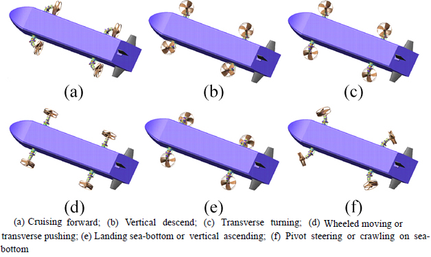
Fig. 1 Typical motions of vectored thruster AUV:
In order to clearly describe the multi-moving state functional requirements of the new AUV, the working process is divided into eight stages, which includes high-speed navigation, low-speed navigation, diving stage, incumbent measurement, wheel travel, seabed crawl, float upwards and communications, as shown in Fig. 2. The order of work process can be changed arbitrarily in accordance with the movement needs. The AUV can exhaust quickly the water in heave system to go up for the safety in case of emergency.
2.1 Design of piston type heave subsystem
The piston type heave subsystem can complete the distribution and adjustment of gravity and buoyancy, which plays an important role in the work-stage conversion from the working process of the new AUV. In the initial stage of AUV cruising and dive, the gravity is substantially equal to the buoyancy. The center of buoyancy is just above the center of gravity at 0.027 m to ensure a certain rotational torque. When the AUV is landing, measuring in stable reign and maneuvering in the seabed, the system gravity needs to be greater than buoyancy, so as to maintain the stability of the AUV. When the AUV needs to go up for communication, the system buoyancy needs to be greater than gravity, so as to make the body go up. At present, the heave manners of domestic and foreign existing AUVs depend on the rudder or ballast tanks basically, which not only need the strict weight requirements for the system, but also have difficultly in adjusting the distribution of the gravity and buoyancy during the voyage of the AUV. So it can not be applied to the new AUV.
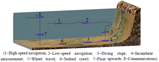
Fig. 2 Working process of new AUV
The piston type heave system designed in this work is composed by housing, hydraulic cylinders, pistons, injection/drainage, drive shaft, slide rails, and two linear motors, as shown in Fig. 3. The housing of piston type heave system is connected by bolts and nuts in a central position on the bottom of the AUV fixedly. The hydraulic cylinder is connected with the external water environment by injection/drainage tube. The lower surface of the slide rail is fixed on the housing of piston type heave system by bolts and nuts. The hydraulic cylinder and a second linear motor are fixed on the upper surface of the sliding guide by screws. The second linear motor is connected to the piston through the shaft to drive the piston in the hydraulic cylinder to reciprocate, which changes the cavity volume of the hydraulic cylinder. Therefore, the entire buoyancy of the AUV is changed [4]. The first linear motor is fixed to the housing of the piston type heave system by bolts and nuts and connected with the housing of the hydraulic cylinder through the shaft. The AUV reaches a suspended state, maintains the relative position of the piston and the cylinder, but moves the whole through the first linear motor to change the AUV��s center of gravity, which can adjust the pitch attitude of AUV in static state.
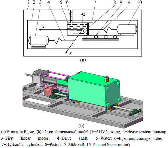
Fig. 3 Piston type heave system:
2.2 Design of a vectorial thruster
According to the designing goals of the new AUV, the vector thruster should have the features of a power drive, attitude realization and spin with holding posture. The vectorial thruster designed in this work is made of a flexible drive shaft and a wheel propeller, as shown in Fig. 4.
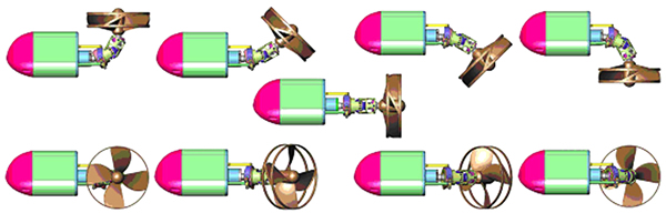
Fig. 4 Attitudes of vectorial thruster based on ball gear
Flexible drive shaft is formed by the spherical gears and the universal joint [5], as shown in Fig. 5(a), the internal structure is shown in Fig. 5(b). The posture of the flexible drive shaft is adjusted and maintained by linear motor No.1 and linear motor No. 2. The spin of flexible drive shaft under current posture is achieved by the main drive motor, which drives the propeller��s rotation in the current space posture and produces the vector propulsion. The flexible drive shaft can be used as wheel-leg function actuators, which can realize two different forms of exercise. One is full range yaw movement of the leg mechanism; the other is rotational movement of the wheel mechanism. When the three motors work simultaneously, the flexible drive shaft can also realize wheel-leg complex functions. This wheel-leg mechanism overcomes some shortcomings of the traditional hybrid mechanism of wheel and leg in structure, which avoids some structural problems and the potential impact on performance [6]. The main advantage is reflected in three aspects, first is the wheel and leg mechanism integrate fully, the second is it works without any auxiliary device, and the third is the drive layout is optimized.
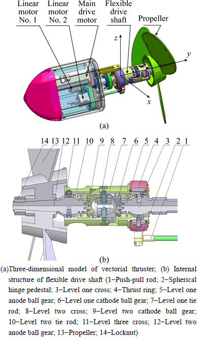
Fig. 5 Vectorial thruster model based on ball gear:
The ducted propeller with a pre-swirl stator or with a stator behind the propeller can be used when only considering the realization of wheel function. However, due to the uniaxial characteristic of the flexible drive shaft mechanism, it can not achieve different shaft drives of a stator and blades. Therefore, a new wheel propeller with the characteristics of large thrust, high structural strength, stable hydrodynamic performance and low blade flutter is designed to achieve the wheel function of propellers based on the characteristics analysis of contracted and loaded tip (CLT) propellers and ducted propellers, as shown in Fig. 6 (R2 is the radius of D4-70 propeller), which breaks design bottleneck of thepropellers with a single function [7]. The flexible drive shaft and the wheel propeller are assembled to complete the vectorial thruster design of the new AUV.
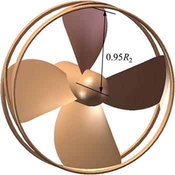
Fig. 6 Geometrical model of WPD4-70 propeller
2.3 Design of measurement and communication module
Measurement and communication module is installed in the new AUV header, which is mainly composed by satellite terminals, navigation and measurement sensor module and its regulation mechanism. Since the sensors account for an important part of the new AUV��s costs, in order to achieve the goals of economic development, the adjustment mechanism is used to achieve sensors�� reuse. Since the new AUV should float to the sea surface to complete communication tasks, the module should be designed to the minimize weight.
According to the design objectives, a rotary motor is used to drive gear mechanism, which drives the measurement sensor module to rotate around the longitudinal axis of the AUV��s body. Simultaneously, the pendulum is used to complete the passive adjust of the measurement sensor module around the swung axis (y axis), which achieves sensors�� reuse, as shown in Fig. 7. When the new AUV sails, the sensor module keeps straight down to complete the pose control such as speed, heading, range, and inclination. When the new AUV lands on the complex seabed surface, the sensor module keeps vertically upwards under double adjust of the gear transmission mechanism and the pendulum. As the measurement sensor is always up during operation, the impact of seabed topography condition on the AUV��s attitude is eliminated.
2.4 Design of manipulation module
Rudder system is the main control mechanism of heading control when the new AUV navigates at high speed. According to the functional requirements of themulti-moving state AUV, the vertical rudder on the lower side should have a retractable function, which is suitable for the new AUV��s landing and submarine maneuver. The typical transmission methods of conventional rudder system design are belt drive, chain drive, wire drive, gear drive, etc, the steering system of the new AUV uses a gear transmission mechanism through comprehensive comparison, which has significant advantages of high transmission efficiency and high precision movement.
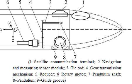
Fig. 7 Schematic diagram of measurement and communication module
The rudder system includes vertical rudder mechanism and horizontal rudder mechanism. Since the horizontal rudder and the vertical rudder are orthogonal to each other. Both rudder shaft axes are arranged in the same cross-section perpendicular to the tail of the new AUV��s body. Therefore, the two rudder shaft axes can not be designed to be a through shaft, only independent of each other. The rotary motors drive the two same gear mechanisms to control the left and right horizontal rudders respectively, which can guarantee the same swung angle on both sides. The self-locking performance of worm gear maintains the existing angle after the rudders on both sides swung at a certain angle, which reduces the energy consumption of the motors. The vertical rudders use two rotary motors to control the rudders�� swung on the both sides and the rudder��s fold on the lower side. A rotary motor is used to control the swung angle of rudders on both sides when the new AUV is sailing, which achieves the purpose of heading control. When new AUV is landing or moving on the seabed, the other rotary motor is used to control the rudder��s fold on the lower side, which can avoid clashing with the seabed. The rudder system is shown in Fig. 8.
2.5 Layout and design of control system
The layout and design of the new AUV��s control system is not only necessary to meet the functional requirements of multi-moving state, but also fits sensor to complete data measurement and communications. The heave system, drive system, measurement system and steering rudder system have been designed previously.The overall layout of the new AUV��s control system is designed as shown in Fig. 9 combined with the structural characteristics of each subsystem and the functional requirements of multi-moving state.
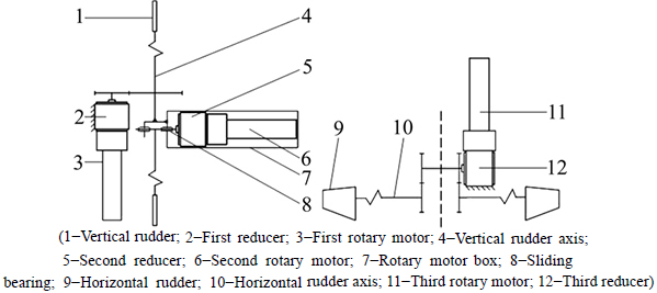
Fig. 8 Schematic diagram of rudder system
In order to achieve modular, sub-cabin design and functional expansion of the new AUV, the overall structure of the control system is designed as distributed architecture, as shown in Fig. 10. The control system is divided into five nodes as follows: 1) main control node which completes the task coordination and planning of the new AUV; 2) navigation sensor nodes which mainly complete the measurement and processing of the new AUV��s navigational status information; 3) task sensor nodes which complete task measurements and data storage of the new AUV; 4) implementation control nodes which complete overall control functions of the new AUV such as driving and attitude adjustment of vectorial thrusters, injection and drainage of piston heave system, AUV��s center of gravity adjustment, measurement module adjustment, swung and fold of steering rudders; 5) troubleshooting nodes which complete monitoring and diagnosis of the sensor information. If an accident permanent fault affects the safety of the AUV, the piston type heave system can complete the implementation of automatic drainage, so that the body floats up.
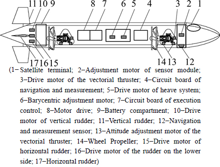
Fig. 9 Schematic diagram of control system layout
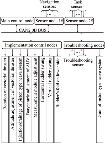
Fig. 10 Schematic diagram of system control module
The AUV��s actuators are controlled by brushless DC servo motors which differ in control mode and parameters of each subsystem. The motor is driven by a three-phase pulse width modulation, the Hall feedback achieves commutation, and the encoder feedback achieves the closed loop of speed or position. The main factors selecting brushless DC servo motors are as follows: 1) this motor has small size and light weight; 2) this motor has no mechanical commutation, which has low noise and can overcome interference of radio generated by commutators and brushes; 3) this motor has certain moisture-resistant and temperature-resistant capability.
3 Theoretical analysis and computation of key technologies
3.1 Performance computation and analysis of vectorial thruster
The kinematics model of the flexible drive shaft is established through coordinate conversion method based on thrust vectoring technology. When the sliding length value or range of two linear motors are given, the posture of flexible drive shaft and the spatial motion range of output terminal can be obtained, as shown in Figs. 11 and 12. Therefore, the vectorial thruster can generatecontrollable vectorial thrust in magnitude and spatial orientation and achieve more than traditional propeller propulsion in order to achieve the same effect of traditional plurality of propeller working together, which greatly simplifies the complexity of the control system and propulsion system [8].
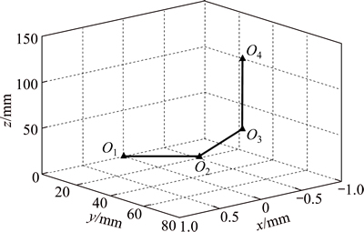
Fig. 11 Space attitude of flexible drive shaft
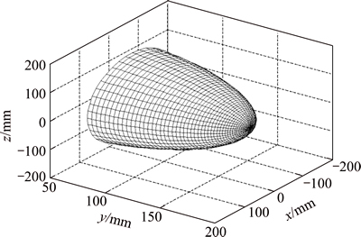
Fig. 12 Space trajectory of flexible shaft��s output end
In order to test stability and spatial attitude adjustments of the vectorial thrusters in hydrostatic propulsion and prevent motors damage, hydraulic drive system and control system are used to make the underwater test in the test pool. Firstly, the attitude control test of the vectorial thruster vector was made, as shown in Fig. 13. The test results show that the vectorial thrusters can complete a full range of yaw motion according to the control command, and the process of attitude adjustment is continuous and stable. In order to further verify the effect of the vectorial thruster in the pool, the yaw and rotation tests were made, as shown in Fig. 14. The test results show that the vectorial thrusters can generate stable thrust in desired direction, and the vectorial thrust transits smoothly in the process of attitude adjustment, which can meet the new AUV��s design requirements.
The propeller is a special kind of complex surface parts. The computational fluid dynamics (CFD) method is applied to explore the numerical methods of the propeller open-water performance by using the RANS equation and three different turbulence models including standard k-e, standard k-w and RSM based on sub- domains hybrid meshes. The governing equations are written for the mass and momentum conservation as
 (1)
(1)

 (2)
(2)
where �� is density, t is time, ui and uj are velocity in the Cartesian coordinate system, is Reynolds stress, �� is molecular viscosity, and p is static pressure.
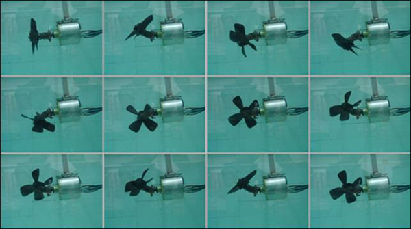
Fig. 13 Attitude control test of vectorial thruster
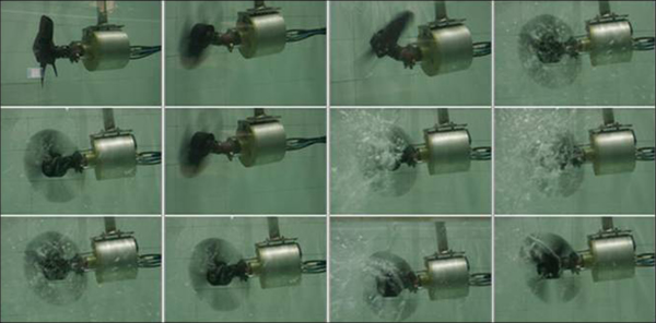
Fig. 14 Underwater test of vectorial thruster
The computational open-water performances of the propellers including DTMB4119, DTRC3745 and D4-70 are in good agreement with the experimental data, which verifies the correctness of solid modeling and numerical methods.The maximum errors of RSM, standard k-e and standard k-w in the computational results of DTMB4119 open-water performance are 5.47%, 7.41% and 11.21%, respectively, which shows that the numerical method using RSM has good accuracy in the prediction of propeller open-water performance. This conclusion may guide the selection of turbulence models in viscous flow computation around complex rotating machine. Some important viscous flow characteristics of the propeller such as flow separation, tip vortex and trailing wake are got, which provides an effective reference for the design of new efficient thruster [9]. A new wheel propeller (WPD4-70) with the advantages of a large thrust, high structural strength, stable hydrodynamic performance and anti-blade flutter is present through a series of propeller open-water performance computation and comparison under the guidance of the characteristic analysis of the ducted propeller and CLT propeller. The open-water performance of the wheel propeller at positive and reversing rotation state is shown in Fig. 15. In order to ensure the security and stability of the AUV when it is moving on the ground, nonlinear buckling analysis based on finite element method is used to compute the maximum allowable load of WPD4-70, the computational result is 3975 N, as shown in Fig. 16 (�� is the angle of the line from landing point to the origin and the y-axis). Meanwhile, the natural frequencies and vibration modes are got through the modal analysis of WPD4-70, each natural frequency is less than the corresponding value of model IV, which indicates that the ability of its vibration insulation in the driving state is enhanced. The past four vibration modes show that the first vibration mode (main vibration mode) is thedistortion of the blades and the remaining modes are the radial stretching the edge of the wheel. The final WPD4-70 has preferable open-water performance and intensity characteristics, which can realize the functional requirements of the multi-moving state AUV [10].
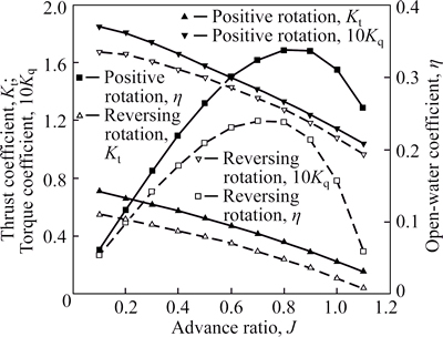
Fig. 15 Open-water performance of wheel propeller at positive and reversing rotation state
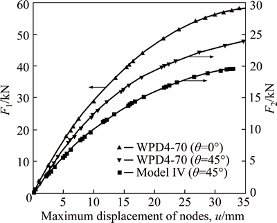
Fig. 16 Relation curve between load and maximum displacement of nodes
3.2 Dynamics analysis of new AUV
Euler angles representation is applied to establish six-DOF nonlinear kinematic model according to the structural characteristics and motion characteristics of the new AUV. The dynamic equations in the inertial coordinate system can be expressed as

 (3)
(3)
where 


 J(��) is the transformation matrix between the body-fixed coordinate system and the inertial coordinate system, M is the mass matrix, C(v) is the Coriolis and centripetal matrix, D(v) is the hydrodynamic damping matrix, fT is the control forces and moments, fC is the ocean currents forces and moments, fW is the waves forces and moments and g(��) is the subtractive restoring forces and moments vector.
In order to achieve the satisfactory performance with arbitrary angles, the quaternion method is used to solve the especial singularities when the pitch angles are ��90o, as shown in Fig. 17. The Newton second law and Lagrangian approach are used to deduce the vectored thruster AUV��s nonlinear dynamic equations with six degrees of freedom (DOF) respectively in complex sea conditions based on the random wave theory, the dynamic models of the two methods are the same, which shows that the dynamic model of the vectored thruster AUV is accurate [11]. On this basis, the mathematical model of the new AUV��s low-frequency motion and high-frequency motion in complex sea conditions are established. The Runge-Kutta arithmetic is used to solve the dynamic equations, which not only can simulate the motions such as cruise and hover but also can describe the vehicle��s low-frequency and high-frequency motion, so this method clears up the difficulties of computation and display of the coupled nonlinear motion equations in complex sea conditions. The kinematic model and dynamic model are proved to be valid through the computation and analysis of its spatial motion��s performance in interference-free environment and the analysis of the integrated signals including low- frequency motion signal and high-frequency motion signal in environmental interference, as shown in Figs. 18 and 19, which shows that the maneuverability of the vectored thruster AUV equipped with rudders and vectored thrusters is enhanced. Furthermore, it is necessary to filter the measurement of the new AUV��s position and orientation signal in complex sea conditions, and the low-frequency motion signal control can effectively avoid the problem of energy waste and propeller wear [12].
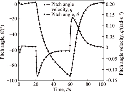
Fig. 17 Curves of pitch angle �� and pitch angle velocity q
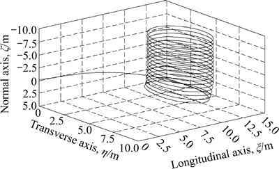
Fig. 18 Motion trajectory of spiral ascending process
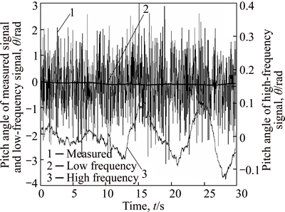
Fig. 19 Curves of pitch angle �� in complex sea condition
3.3 Controller performance analysis of new AUV
The fastness and stability of the new AUV in complex sea conditions need the control system with strong robustness to complete. In order to solve the nonlinear term and unmodeled dynamics existing in the new AUV��s attitude control and the disturbances caused by the external marine environment, a second-order sliding mode controller with double-loop structure considering the dynamic characteristics of the rudder actuators is designed. Then Lyapunov stability theory is used to verify the stability of the controller. The impacts of system parameters, rudder actuator��s constraints and boundary layer on the sliding mode controller are computed and analyzed to verify that the sliding mode controller based on dynamic boundary layer can effectively resolve sliding mode loss in the attitude control caused by the rudder actuator amplitude and rate limiting and avoid the control failure caused by that the design theory does not match with the actual application conditions [13]. According to the submarine theory, six-DOF motion equations of the new AUV are decomposed into two mutually non-coupled subsystems, namely the horizontal plane subsystem and the vertical plane subsystem. As the yaw angle and yaw angle rate rather than the displacement of the new AUV can be measured directly in the horizontal plane, the sliding mode control algorithm combining cross track error method and line of sight method is used to fulfill its high-precision trajectory tracking control in different sea conditions, which ensures the robustness and accuracy of the sliding mode controller when the heading error is too large, as shown in Fig. 20.
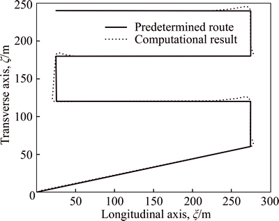
Fig. 20 Trajectory tracking result in random currents
The control law of the sliding mode controller based on the line of sight method is designed as
 (4)
(4)
where  is the reaching law of the sliding surface, ��2 is the maximum of the reaching law, f2 determines the decay law of the sliding surface when its amplitude decreases, r(t) is the angular velocity of the yaw angle and ��2(t) is the slide surface, and K1 is the adjustable coefficient.
As the vertical displacement of the new AUV can be measured, a stable sliding mode controller is designed based on the single-input multi-states system��which takes into account the characteristic of the hydroplane and the amplitude and rate constraints of the hydroplane angle. Moreover, the using of dynamic boundary layer improves the robustness and control accuracy of the system, which realizes the accurate tracking of time-varying depth signal with the desired attitude in different sea conditions, as shown in Fig. 21. The impacts of currents and waves on the sliding mode controller of the new AUV are analyzed qualitatively and quantitatively by comparing the trajectory tracking performance of the new AUV in different sea conditions, which provides an effective theoretical guidance for the control system design of the new AUV in real complex environment [14].
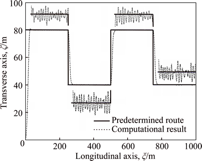
Fig. 21 Depth tracking result in random waves
3.4 Flow field characteristics analysis of new AUV
The hydrodynamic characteristics of the viscous flow field around the new AUV in complex sea conditions are studied. The CFD method is used to simulate numerically the unsteady viscous flow around the new AUV with propellers in non-environmental interference conditions by using the RANS equations, SST k-w model and pressure implicit with splitting of operators (PISO) algorithm based on sliding mesh. The SST k-w turbulence model can be written in Cartesian tensor form as
 (5)
(5)
where k is turbulence kinetic energy, w is specific dissipation rate, Gk is effective diffusivity of k, Gw is effective diffusivity of w, Gk is generation term of k due to mean velocity gradient, Gw is generation term of w due to mean velocity gradient, Yk is dissipation term of k due to turbulence, Yw is dissipation term of w due to turbulence, and Dw is the cross-diffusion term.
The computational results have good convergence, which reflects well the real ambient flow field of the new AUV with propellers, as shown in Figs. 22 and 23. The interaction between AUV hull and wheel propellers is predicted qualitatively and quantitatively by comparing the hydrodynamic parameters such as resistance, pressure and velocity that from integral computation and partial computation of the viscous flow around the AUVwith propellers in non-environmental interference conditions, which provides an effective reference to the optimization design, vibration and noise of the AUV hull and propellers in real environment [15]. The communication tasks usually require the new AUV to navigate on the sea surface in complex sea conditions. Therefore, the movement forms and flow field characteristics of the new AUV navigating in head sea at high speed are necessary to be studied. The mathematical model of the high-speed AUV in head sea is established considering the hydrodynamic lift based on strip theory according to the motion characteristics of the new AUV in waves, which is solved to get the heave and pitch of the AUV by Gaussian elimination method. Then the motion processes of the AUV��s heave and pitch are realized in the numerical computation of the flow field around the AUV based on the dynamic mesh that driven by the UDF function source code compiled with DEFINE_CG_MOTION macro. According to the coordinate transformation principle of AUV��s longitudinal motion theory and the technique of purely numerical wave based on the UDF function source code compiled with DEFINE macro, the three-dimensional numerical wave of the computational field is realized through defining the unsteady inlet boundary condition. On this basis, the CFD theory is used to establish the mathematical model of the unsteady viscous flow around the AUV considering free surface effort by using the RANS equations, SST k-w model and VOF model. The hydrodynamic parameters of the AUV such as drag, lift, pitch torque, velocity, pressure and wave profile are gotten by numerical computation, which predicts well the real flow field around the high-speed AUV in head sea. The computational wake of the AUV is in good agreement with the experimental phenomenon of a wave-piercing surface vehicle, as shown in Fig. 24, which verifies effectively the correctness of the numerical method [16].
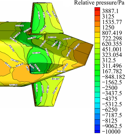
Fig. 22 Relative pressure of AUV with propellers
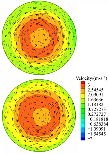
Fig. 23 Computational velocity field at 0.25D behind propeller plane
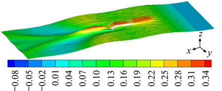
Fig. 24 Wave profiles of free surface (Unit: m)
4 Conclusions
1) In order to achieve multi-moving state functions of the new AUV, the main and accessory structures adopt the separable form. The heave system, vectorial thruster, measurement and communication module, manipulation module and control system are designed. The structure and working principle of each system are made a detailed analysis.
2) The numerical methods of open-water performance and strength characteristics for propellers are explored based on finite volume method and finite element method, and then a new wheel propeller is designed.
3) The kinematic model and dynamic model of the new AUV are established, and the dynamic characteristics of the AUV in interference and interference-free environment are computed and analyzed, which verifies the validity mathematical models.
4) In order to meet design requirements of the control system in complex sea conditions, a sliding mode controller with high stability is designed, and the trajectory tracking performance is computed and analyzed.
5) Numerical method of the new AUV��s viscous flow in complex sea conditions were studied, and its hydrodynamic characteristics in interference and interference-free environment are computed and analyzed.
References
[1] PAULL L, SAEEDI S, SETO M, LI H. AUV navigation and localization: A review [J]. Ocean Engineering, 2014, 39(1): 131-149.
[2] LUDVIGSEN M, JOHNSEN G, LAGSTAD P A, SRENSEN A J, DEGARD Y. Scientific operations combining ROV and AUV in the Trondheim Fjord [J]. Oceans, 2013, 48(2): 1-7.
[3] PAN Cun-yun, WEN Xi-shen. Research on transmission principle and kinematic analysis for involut spherical gear [J]. Chinese Journal of Mechanical Engineering, 2005, 41(5): 1-9. (in Chinese)
[4] XU Han-jun, PAN Cun-yun, XIE Hai-bin, ZHANG Dai-bing. Dynamics modeling and simulation of a bionic swim bladder system in underwater robotics[J]. Journal of Bionic Engineering, 2008, 5: s66-s71.
[5] ZHANG Li-jie, PAN Cun-yun, LI Ming-yu, LI Ting. Kinematics analysis and simulation of the omni-directional deflection joint [J]. Machine Design and Research, 2007, 23(3): 27-36. (in Chinese)
[6] ZHANG Li-jie, PAN Cun-yun, LI Ming-yu, LI Ting. A new wheel-legged locomotive system composed of bionic joints [J]. China Mechanical Engineering, 2009, 20(18): 2142-2148. (in Chinese)
[7] GAO Fu-dong, PAN Cun-yun. Parameterized design and analysis of the complicated curved-surface propeller in solid modeling [J]. Mechanical Science and Technology for Aerospace Engineering, 2011, 30(1): 1-5. (in Chinese)
[8] XU Hai-jun, PAN Cun-yun, FANG Shi-peng, DENG Hao. Solution and analysis on the orientation of the screw propeller in the flexible-axis thruster [J]. Journal of Mechanical Transmission, 2009, 33(3): 4-10. (in Chinese)
[9] GAO Fu-dong, PAN Cun-yun, YANG Zheng. Numerical analysis and validation of propeller open-water performance based on CFD [J]. Journal of Mechanical Engineering, 2010, 46(8): 133-139. (in Chinese)
[10] GAO Fu-dong, PAN Cun-yun, XU Hai-jun, ZUO Xiao-bo. Design and mechanical performance analysis of a new wheel propeller [J]. Chinese Journal of Mechanical Engineering, 2011, 24(5): 805-812.
[11] GAO Fu-dong, PAN Cun-yun, YANG Zheng, FENG Qing-tao. Nonlinear mathematics modeling and analysis of the vectored thruster autonomous underwater vehicle in 6-DOF motions [J]. Journal of Mechanical Engineering, 2011, 47(5): 93-100. (in Chinese)
[12] GAO Fu-dong, PAN Cun-yun, XU Xiao-jun, ZHANG Xiang. Nonlinear dynamic characteristics of the vectored thruster AUV in complex sea conditions [J]. Chinese Journal of Mechanical Engineering, 2011, 24(6): 935-946.
[13] GAO Fu-dong, PAN Cun-yun, HAN Yan-yan. Design and analysis of a new AUV��s sliding control system based on dynamic boundary layer [J]. Chinese Journal of Mechanical Engineering, 2013, 26(1): 35-45.
[14] GAO Fu-dong, PAN Cun-yun, HAN Yan-yan, ZHANG Xiang. Nonlinear trajectory tracking control of a new AUV in complex sea conditions [J]. Journal of Central South University, 2012, 19(7): 1859-1868.
[15] GAO Fu-dong, PAN Cun-yun, HAN Yan-yan. Numerical computation and analysis of unsteady viscous flow around the AUV with propellers based on sliding mesh [J]. Journal of Central South University, 2012, 19(4): 944-952.
[16] GAO Fu-dong, PAN Cun-yun, XU Xiao-jun, HAN Yan-yan. Numerical computation and analysis of high-speed AUV moving in head sea based on dynamic mesh [J]. Journal of Central South University, 2012: 19(11): 3084-3093.
(Edited by FANG Jing-hua)
Cite this article as:
GAO Fu-dong, HAN Yan-yan, WANG Hai-dong, JI Gang. Innovative design and motion mechanism analysis for a multi-moving state autonomous underwater vehicle [J]. Journal of Central South University, 2017, 24(5): 1133-1143.
DOI:https://dx.doi.org/10.1007/s11771-017-3516-7Foundation item: Project(51505491) supported by the National Natural Science Foundation of China; Project(ZR2014EEP019) supported by the Natural Science Foundation of Shandong Province, China
Received date: 2015-10-06; Accepted date: 2015-12-13
Corresponding author: GAO Fu-dong, Lecturer, PhD; Tel: +86-532-58833378; E-mail: gaofudong2005@163.com
Abstract: In order to achieve the functional requirements of multi-moving state, a new autonomous underwater vehicle (AUV) provided with the functions such as the submarine vectorial thrust, landing on the sea bottom, wheel driving on the ground and crawling on the ground was designed. Then five new theories and methods were proposed about the motion mechanism of the AUV such as vectorial thruster technology, design of a new wheel propeller, kinematics and dynamics, navigation control and the ambient flow field in complex sea conditions, which can all conquer conventional technique shortages and predict the multi-moving state performance under wave disturbance. The theoretical research can realize the results such as a vectorial transmission shaft with the characteristics of spatial deflexion and continual circumgyratetion, parameterized design of the new wheel propeller with preferable open-water performance and intensity characteristics satisfying multi-moving state requirements, motion computation and kinetic analysis of AUV��s arbitrary postures under wave disturbance, a second-order sliding mode controller with double-loop structure based on dynamic boundary layer that ensures AUV��s trajectory high-precision tracking performance under wave disturbance, fast and exact prediction of the ambient flow field characteristics and the interaction mechanism between AUV hull and wheel propellers. The elaborate data obtained from the theoretical research can provide an important theoretical guidance and technical support for the manufacture of experimental prototype.
