
Trans. Nonferrous Met. Soc. China 27(2017) 1273-1284
Development of processing windows for friction stir spot welding of aluminium Al5052 /copper C27200 dissimilar materials
S. SIDDHARTH, T. SENTHILKUMAR, M. CHANDRASEKAR
Department of Mechanical Engineering, University College of Engineering, Anna University-Tiruchirappalli, Tiruchirappalli 620 024, India
Received 25 April 2016; accepted 7 September 2016
Abstract:
Friction stir spot welding technique was used to join dissimilar combinations of aluminium alloy (Al5052) with copper alloy (C27200) and friction stir spot welding windows such as tool rotational speed�Cdwell time and tool rotational speed-plunge depth diagrams for effective joining of these materials were developed. Using a central composite design model, empirical relations were developed to predict the changes in tensile shear failure load values and interface hardness of the joints with three process parameters such as tool rotational speed, plunge depth and dwell time. The adequacy of the developed model was verified using ANOVA analysis at 95% confidence level. Response surface methodology was used to optimize the developed model to maximize tensile strength and minimize interface hardness. A high tensile shear failure load value of 3850 N and low interface hardness value of HV 81 was observed for joints made under optimum conditions, and validation experiments confirmed the high predictability of the developed model with error less than 2%. The operating windows developed shall act as reference maps for future design engineers in choosing appropriate friction stir spot welding process parameter values to obtain good joints.
Key words:
friction stir spot welding; dissimilar materials; aluminium; copper; processing windows; response surface methodology;
1 Introduction
Copper and brass find an important place in industrial applications owing to their superior fatigue and corrosion resistance, high strength, good electrical and thermal conductivities [1]. Aluminum and its alloys find importance as light weight components with improved mechanical response. Dissimilar aluminum and copper joints are preferred in many practical applications like heat transfer equipment, electrical industries and electronics [2]. Conventional fusion welding processes for joining aluminium and copper poses to be difficult as it leads to formation of hard and undesirable intermetallic phases at the joint interface, leading to cracks [3]. Friction stir welding, a solid state joining process patented by The Welding Institute in 1991 [4], has been widely used for joining dissimilar materials having differences in mechanical and metallurgical properties. Friction stir spot welding (FSSW) is its linear variant used for spot joining applications, poses to be a better option for joining dissimilar materials than resistance spot welding [5].
FSSW is a three step process that involves first, plunging of a non-consumable rotating tool into the job, next a period of dwell during which the tool is allowed to induce frictional heat for a specific time duration and finally drawing out, when the rotating tool is removed from the weld zone allowing the region to cool [6]. The schematic diagram is shown in Fig. 1. Researchers recommend friction stir spot welding to spot weld dissimilar materials rather than toggle locking, clinching and riveted joining processes [7,8].
The selection of friction stir spot welding process variables affecting the spot weld morphology plays an important role in determining the quality of the joints [9]. The predominant process parameters determining the strength and surface finish of the friction stir spot welded joints are tool rotational speed, dwell time and tool plunge depth [6]. Literatures reported on friction stir spot welding of dissimilar aluminum-copper materials are very few [10-12]. OZDEMIR et al [10] investigated the grain modifications in weld region, HEIDEMAN et al [11] investigated the metallurgical aspects at joint interface and MUBIAYI and AKINLABI [12] evaluated the microstructures of the joints of aluminium-copper FSSW joints. LAKSHMINARAYANAN et al [13] developed friction stir welding windows for joining AA2219 aluminium alloy. Very few research works are available relating optimization of friction stir spot welding process parameters.
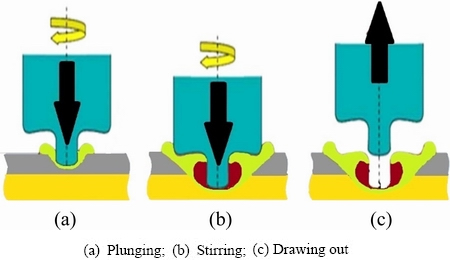
Fig. 1 Three step FSSW process
LAKSHMINARAYANAN et al [9] used response surface methodology and TUTAR et al [14] used Taguchi orthogonal array techniques for optimization of friction stir spot welds. Different prediction techniques can be used for defining the desired output variables, by development of mathematical models and thereby determining the relationship between the input parameters and output variables. Response surface methodology (RSM) is useful in development of a suitable approximation, for determining the relationship between independent and response variables which can effectively characterize the joints [15]. Efficient use of statistical design of the experimental techniques enables the development of empirical methods, thereby enabling incorporation of a scientific and rational approach in solid state joining procedures such as friction stir spot welding [9,14].
In the current investigation, an attempt has been made to develop friction stir spot welding windows such as rotational speed�Cdwell time and rotational speed�C plunge depth diagrams for effective friction stir spot welding of Al5052 aluminium alloy and C27200 copper alloy. Moreover, in this research, optimization of friction stir spot welding process parameters for obtaining maximum tensile shear failure load and minimum interface hardness of Al 5052-C27200 joints using RSM, was attempted.
2 Experimental
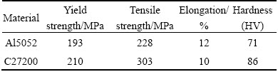
The base materials used in this investigation were aluminium alloy Al5052 (1.5 mm thick) and (ASTM B-111) copper alloy C27200 (1.6 mm thick). They were sized to 100 mm in length and 30 mm in breadth. The chemical composition and important mechanical properties of the base materials are given in Tables 1 and 2, respectively.
Table 1 Nominal chemical compositions of base materials (mass fraction, %)
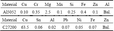
Table 2 Important mechanical properties of base materials
The welding surfaces of the samples were cleaned to remove dirt and impurities and the surfaces were cleaned with acetone before clamping in the fixture for spot welding. Lap configuration was used and Al5052 was made to be on the top side with the lap configuration directly coming under contact with the tool. The non-consumable tool was made with hardened tool steel H13 material [12]. Cylindrical straight profile was chosen for tool nomenclature and the tool was made with an overall length of 125 mm, with a geometry of 16 mm shoulder diameter, 6 mm pin diameter and 1 mm length (Fig. 2).
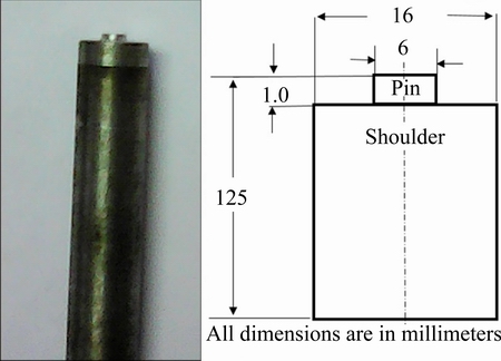
Fig. 2 FSSW tool nomenclature
The schematic representation of the friction stir spot welding setup is shown in Fig. 3(a), and the CNC controlled heavy type vertical milling machine used for performing the experiments is shown in Fig. 3(b).
The non-consumable high speed rotating tool is made to plunge with a very slow feed rate of 25 mm/min so as to eliminate impact contact between the tool and the jobs. From the friction stir spot welding process parameters the three important process parameters which affected the joint quality were tool rotational speed, plunge depth and dwell time [6]. FSSW joints were fabricated by varying the three important process parameters. After completion of the spot welding, the specimens were tested for their tensile strength using an electro-pneumatically controlled universal testing machine. The size of the tensile test specimens as per ASTM standards is shown in Fig. 4.
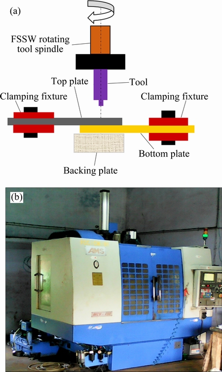
Fig. 3 Schematic representation of FSSW setup (a) and equipment used for FSSW experiments (b)
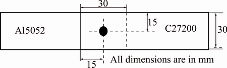
Fig. 4 Tensile test specimens as per ASTM standards
As per standard specifications of ASTM, the samples were loaded at a uniform rate of 1.5 kN/min till fracture of the specimens.
3 Development of friction stir spot welding windows
The selection of friction stir spot welding process variables affecting the joint interface, structural morphology, extent of flash formation, keyhole size, appearance of the spot weld are critical for attainment of good quality spot welds. The friction stir spot welds were fabricated by varying the important process parameters such as tool rotational speed, dwell time and plunge depth as given in Table 3. To evaluate the weld strength, lap shear tensile tests were conducted and the corresponding tensile shear failure load values were tabulated and presented in Table 3. From the results the following inferences were tabulated.
1) When the tool rotational speed was lower than 1000 r/min, no welding occurred between Al and Cu alloy and this was attributed to low heat generation in the weld region (Fig. 5(a)).
2) When the tool rotational speed was greater than 1600 r/min, the welding did not take place properly due to the excessive heat generated in the weld zone and melting of Al alloy (Fig. 5(b)).
3) When the plunge depth was less than 0.75 mm, due to lack of penetration of the tool into the bottom sheet, stirring effect was not enough to produce proper welds (Fig. 5(c)).
4) When the plunge depth was greater than 2.25 mm, excessive penetration of the sheets by the tool caused deformation of the weld zone, increasing the keyhole size drastically, thus resulting in improper welds (Fig. 5(c)).
5) When the dwell time was less than 10 s, the heat generated during the entire process was not enough to soften the weld zone and did not weld the plates (Fig. 5(d))
6) When the dwell time was greater than 18 s, the excessive heat generated due to the excessive stirring of the tool melted the plates and resulted in improper welds (Fig. 5(e)).
Within the limits, above 1000 r/min and below 1600 r/min of the tool rotational speed, greater than 0.75 mm and less than 2.25 mm plunge depth, and a period of dwell between 10 and 18 s, the friction stir spot welds of Al5052 and C27200 were of good quality. Friction stir spot welding windows of two types were constructed for Al5052-C27200 joints.
First sets were prepared by plotting the variation of tool rotational speed, which was taken in Y axis and dwell time taken in X axis. At a constant plunge depth of 1.25 mm, tool rotational speed in r/min and dwell time in second were varied to plot the working (processing) limits and the friction stir spot welding window (FSSWW) was constructed. Similarly, experiments were conducted to find out the working limits for the plunge depths of 1.75 mm and 2.25 mm, respectively. These points were used for construction of tool rotational speed�Cdwell time operating limit diagram, for the three plunge depths and displayed in Fig. 6. The selection of friction stir spot welding process parameters within the operating windows yielded good spot welds between Al-Cu joints and it was validated by conducting few more experiments.
Table 3 Experimental values with their corresponding lap shear tensile failure loads
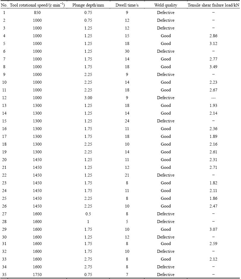
Tool rotational speed�Cplunge depth operating limit diagrams were constructed by keeping tool rotational speed in Y axis and plunge depth in X axis. At a constant dwell time of 10 s, the tool rotational speed and plunge depth were varied to find out the working limits. Similarly, experiments were conducted to find out the working limits for dwell time of 14 and 18 s, respectively. These points were used for construction of tool rotational speed �Cplunge depth operating windows for the three dwell time and they are shown in Fig. 7. The selection of friction stir spot welding process parameters within the tool rotational speed-plunge depth diagrams yielded good quality spot welds between Al5052-C27200 dissimilar joints. These were validated by conducting few more experiments, selecting process parameters within the windows.
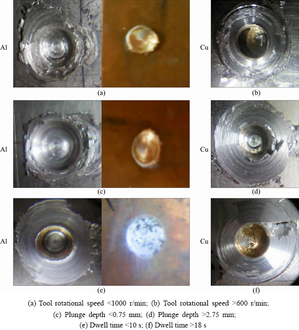
Fig. 5 Photographs of Al 5052�CC27200 joints fabricated above upper limit and below lower limits of process parameters
4 Development of empirical relationships
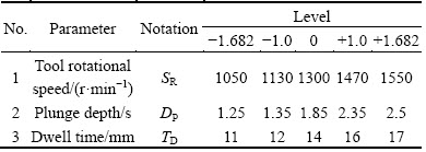
In this investigation, an attempt was made for prediction of tensile shear failure load of friction stir spot welded dissimilar joints of Al5052 and C27200 alloys, incorporating friction stir spot welding process parameters using statistical analysis techniques such as design of experiments (DOE), analysis of variance (ANOVA). The objective was to attain high value of tensile shear failure load values and low interface hardness values (at the spot joint interface of Al-Cu joints). To attain this objective, the feasible limits of spot joining process parameters were chosen from the developed FSSW operating limit diagrams, in such a way that the friction stir spot welds were free from visual cracks and defects. The important factors that influence the tensile shear failure load and interface hardness of the friction stir spot joints and the working range of the dissimilar combination of Al5052/C27200 were identified and they are presented in Table 4.
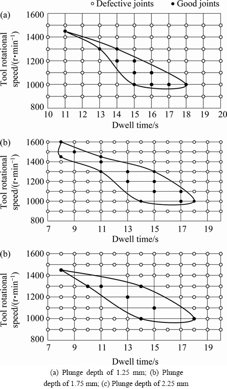
Fig. 6 Tool rotational speed�Cdwell time friction stir spot welding windows
As the ranges of the individual factors were wide, a three factor central composite design matrix was chosen, and five levels were chosen. With eight design points, six star and center points were used for the construction of the central composite design. The matrix was designed as per the method discussed by MONTOGOMERY [16], and listed in Table 5. +1.68 and -1.68 were coded as the upper and lower limits for the design matrix. The intermediate values of the process parameters were found by using the relationship given by MONTGOMERY [16].
Xi=1.682[2X-(Xmax+Xmin)]/(Xmax+Xmin) (1)
In the equation given above, the coded value of the variable X is Xi. From Xmin to Xmax, X assumes any value of the variable. The lowest variable level is denoted as Xmin and the highest level is taken as Xmax. Friction stir spot welds were made as per the process parameter conditions dictated by the design matrix (Table 5). 20 such joints were fabricated and a few are shown in Fig. 8.
Universal testing machine (Electro-mechanically controlled) was used for finding the tensile shear failure load values and Vickers micro hardness testing equipment was used for finding out the microhardness at the interface of the dissimilar joints. The results were recorded and listed in Table 5.
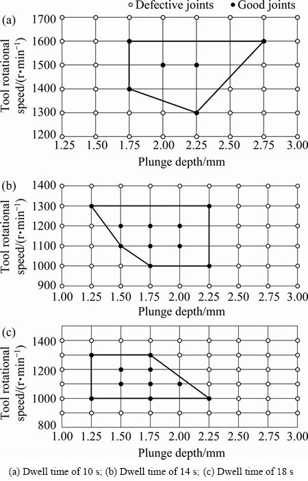
Fig. 7 Tool rotational speed�Cplunge depth friction stir spot welding window
Table 4 Feasible working limits of friction stir spot welding parameters for Al5052/C27200 alloys
Tensile shear failure load of the dissimilar friction stir spot welded joints (LTSF), interface microhardness (HI) are represented as a function of tool rotational speed (SR), plunge depth (DP) and dwell time (TD). According to the methodology suggested by PAVENTHAN et al [17], its relationship is expressed as given below:
LTSF=f{SR, DP, TD} (2)
HI=f{SR, DP, TD} (3)
The response surface M of tensile shear failure load (LTSF) or interface hardness (HI) is represented by second order polynomial regression equation [16]:
 (4)
(4)
For the tool rotational speed (SR), dwell time (TD) and plunge depth (DP), the expression of the polynomial can be given as
LTSF or HI={b0+b1SR+b2DP+b3TD+b12SR��TD+b13SR��DP+b23TD��DP+b11SR2+b22TD2+b33DP2} (5)
The average of responses is given by b0, b1, b2, b3, ��, b33 are the regression coefficients that depend upon linear term, interaction and squared terms of factors [16]. Using design expert software, the coefficients were calculated, whose significance was determined using Student��s t test and p values. Analyses of variance (ANOVA) results were obtained for the tensile shear failure load model for Al5052/C27200 combination and tabulated in Table 6. Similarly, the ANOVA results for the interface hardness values were tabulated in Table 7. ��Prob>F�� values determine that the terms of the model are significant at 95% confidence level as it is less than 0.0500. When the values are greater than 0.10, the model terms are not significant. For the construction of empirical relationships for tensile shear failure load and interface hardness of Al5052/C27200 joints the coefficients were used.
Table 5 Central composite design matrix and experimental results
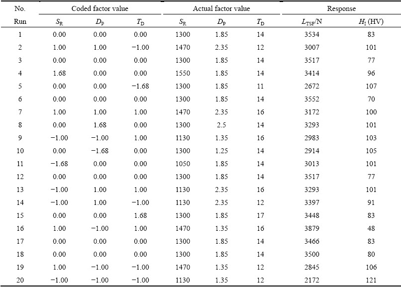
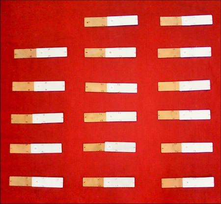
Fig. 8 Photograph of friction stir spot welded Al 5052/C27200 joints
After determination of the significant coefficients at 95% confidence level, the final model developed was developed with the obtained coefficients, and the final empirical relationship for estimation of tensile shear failure load values of the friction stir spot welded Al5052-C27200 dissimilar joints is given in the following.
LTSF={+3514.59+127.96SR+118.67DP+235.67TD�C260.77SR��DP+62.50SR��TD-221.98TD��DP�C110.22SR2-146.79TD2-162.03DP2} (6)
Similarly, the empirical relationships for estimation of interface hardness of the dissimilar Al-Cu alloy joints is given by
HI={+78.45-5.08SR+0.60DP-7.86TD+9.87SR��DP-6.37SR��TD+10.62TD��DP+6.35SR2+7.93TD2+162.03DP2} (7)
Table 6 Analysis of variance results for tensile shear failure load model
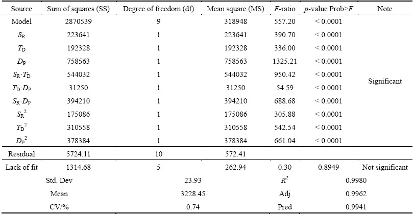
Table 7 Analysis of variance results for interface hardness model
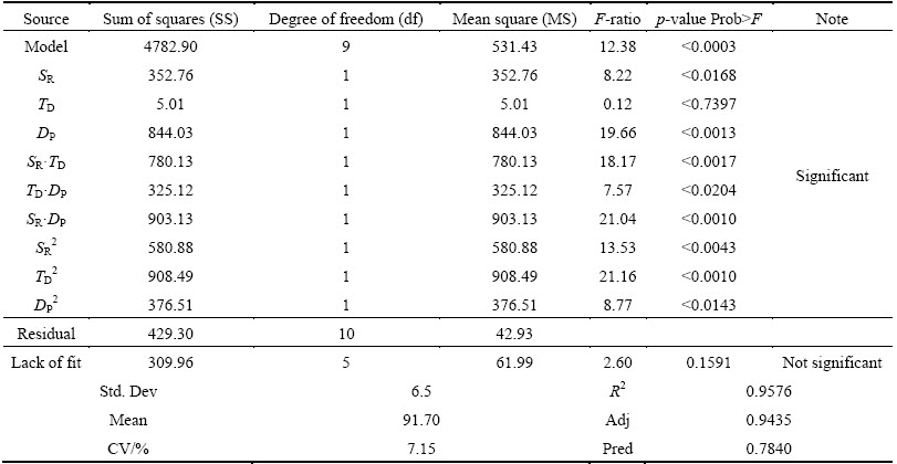
Analysis of variance (ANOVA) method was used for evaluating the relationships that were developed and the adequacy was also checked. From the second order response surface model developed, the results were obtained. The fitted values for evaluation of the tensile shear failure loads and interface hardness are given in Table 6 and Table 7.
R2 is the determination coefficient for the analysis setup which determines the goodness of fit for LTSF and HI model. In this developed model, the obtained determination coefficient R2 indicates that only 5% of the variations are left unexplained [18]. The values of adjusted determination coefficient (adjusted R2) should be high, which plays an important role in clarification of highest level of significance for the developed model. The agreement with the adjusted determination coefficient is observed with predicted R2 values. Comparison of predicted values according to the design points corresponding to the average prediction error is given by adequate precision. The values of determination coefficient was found to be high, which gives a clear indication that a very high correlation exists between the experimental values and the predicted results. The correlation between predicted and actual values of tensile shear failure load values for Al5052/C27200 joints is shown in Fig. 9(a) and that of interface hardness is shown in Fig. 9(b)
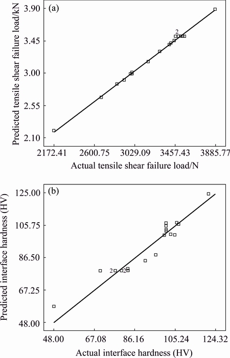
Fig. 9 Correlation between predicted and actual tensile shear failure load values (a) and interface hardness (b)
5 Optimization of friction stir spot welding parameters
Response surface methodology (RSM) was used for optimization of the dissimilar friction stir spot welding process parameters. RSM is a collection of statistics and mathematical analysis techniques that are used for development of mathematical model that can be used for analyzing the optimum combinations of input parameters and expressing the values in graphical format [19]. For prediction of the influence of the optimized conditions of the process variables on tensile shear failure load values and interface hardness, the surface and contour plots were developed for the proposed empirical relationship. The response contours are helpful for predicting the response for any zone within the experimental domain [20]. The apex of the response contours helps in indicating the maximum achievable values. The contour plots were developed to display the regions of optimal factors. The complexity of second-order responses is more pronounced than simple first order models. After the identification of the stationary point, the characterization of response surface in the immediate vicinity of the point is necessary. Identification whether the stationary point is for minimum response, maximum response or saddle point, is the major aspect of its characterization. For classification, it is required to examine the contour plots. Figure 10 shows the contour plots for tensile shear failure load model and Fig. 11 displays the contour plots for interface hardness model.
Response plots for achieving the maximum tensile shear failure load values and minimum interface hardness were developed. In Fig. 12, the surface response plots for tensile shear failure loads are shown.
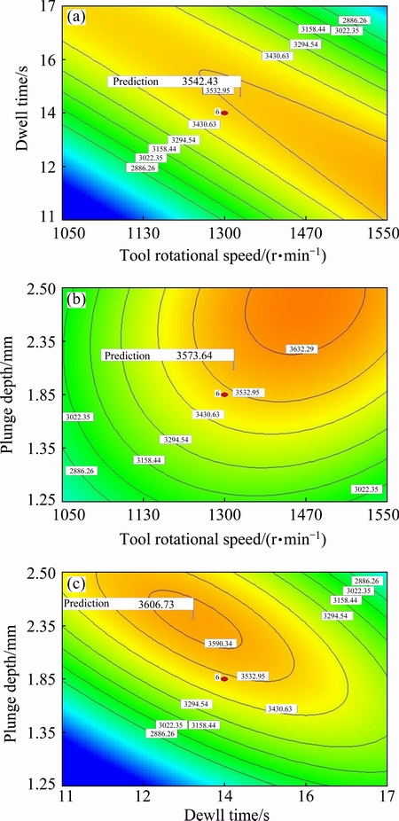
Fig. 10 Contour plots for tensile shear failure load
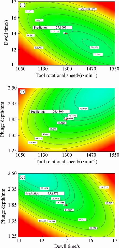
Fig. 11 Contour plots for interface hardness
There is an increase in tensile shear failure load value with the increase in tool rotational speed, dwell time and plunge depth for a certain range and then it decreases. In Fig. 13, the surface response plots for achieving minimum interface hardness are shown.
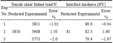
After analyzing and evaluating the contour and response plots, the maximum tensile shear failure load of the Al5052 and C27200 joints was found to be 3850 N and the minimum hardness value was found to be HV 81. The corresponding friction stir spot welding process parameters were, tool rotational speed of 1350 r/min, plunge depth of 1.95 mm, dwell time of 13.5 s. For confirming the predicted values of tensile shear failure load and interface hardness values, by response surface methodology, validation experiments were conducted. Three experiments were conducted with the optimized process parameter values and the errors between the predicted values and the obtained results were recorded and given in Table 8. The maximum errors were found to be 2%, which indicates the soundness of the prediction capability of the optimization model developed.
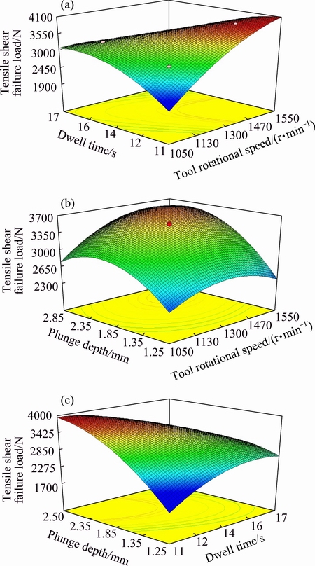
Fig. 12 Surface plots for tensile shear failure load model
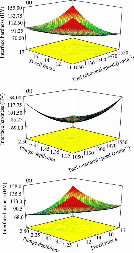
Fig. 13 Surface plots for interface hardness model
Table 8 Results of confirming experiments
6 Conclusions
1) The friction stir spot welding windows were developed, tool rotation speed-plunge depth diagrams and tool rotational speed-dwell time diagrams were developed for identifying the processing regions to join Al5052 aluminium alloy with C27200 copper alloy. These operating limit diagrams were prepared to act as reference maps for future design and welding engineers for selecting appropriate friction stir spot welding process parameters for obtaining good quality dissimilar Al-Cu spot joints.
2) A central composite design matrix was chosen for development of empirical relationship between the important process parameters affecting the tensile strength of the joints such as tool rotational speed, dwell time and plunge depth.
3) Empirical relationships were developed for prediction of maximum tensile shear failure load value and minimum interface hardness for the dissimilar friction stir spot welded Al5083-C27200 joints.
4) Using response surface methodology, the optimized values of input process parameters were found to be tool rotational speed of 1350 r/min, plunge depth of 1.95 mm, and dwell time of 13.5 s.
5) The maximum tensile shear failure load value was 3850 N and the minimum hardness value was found to be HV 81 for the Al5052 and C27200 joints, predicted using the developed optimization model.
References
[1] MUBIAYI M P, AKINLABI E T. Evolving properties of friction stir spot welds between AA1060 and commercially pure copper C11000 [J]. Transactions of Nonferrous Metals Society of China, 2016, 26(7): 1852-1862.
[2] MUBIAYI M P, AKINLABI E T. Friction stir welding of dissimilar materials between aluminium alloys and copper��An overview [C]// Proc World Congress on Engineering 2013. London, U.K: WCE, 2013: 1990-1996.
[3] AKINLABI E T. Effect of shoulder size on weld properties of dissimilar metal friction stir welds [J]. Journal of Materials Engineering Performance, 2012, 21: 1514-1519.
[4] THOMAS W M, NICHOLAS E D, NEEDHAM J C, MURCH M G, TEMPLESMITH P, DAWES C J. Improvements relating to friction welding: TWI Patent, EP0653265 A2 [P]. 1995-05-17.
[5] KHAN I, KUNTZ M L, SU P, GERLICH A, NORTH T H, ZHOU Y. Resistance and friction stir spot welding of DP600: A comparative study [J]. Sci and Tech of Welding and Joining, 2007, 12(2): 175-182.
[6] BADARINARAYAN H. Fundamentals of friction stir spot welding [D]. Missouri University of Science and Technology Doctoral Dissertations 2009.
[7] MALFAIA A M S, MILAN M T, OLIVEIRA M F, SPINELLI D. Fatigue behavior of friction stir spot welding and riveted joints in an Al alloy [J]. Procedia Engineering, 2010, 2(1): 1815-1821.
[8] BRISKHAM P, BLUNDELL N, HAN L, HEWITT R, YOUNG K, BOOMER D. Comparison of self-pierce riveting, resistance spot welding and spot friction joining for aluminium automotive sheet [J]. SAE Technical Paper, 2006, 1: 774-789.
[9] LAKSHMINARAYANAN A K, ANNAMALAI V E, ELANGOVAN K. Identification of optimum friction stir spot welding process parameters controlling the properties of low carbon automotive steel joints [J]. Journal of Materials Research and Technology, 2015, 4(3): 262-272.
[10] OZDEMIR U, SAYER S, YENI C, IZMIR B. Effect of pin penetration depth on the mechanical properties of friction stir spot welded aluminum and copper [J]. Materials Testing in Joining Technology, 2012, 54(4): 233-239.
[11] HEIDEMAN R, JOHNSON C, KOU S. Metallurgical analysis of Al/Cu friction stir spot welding [J]. Science and Technology of Welding and Joining, 2010, 15(7): 597-604.
[12] MUBIAYI M P, AKINLABI E T. Friction stir spot welding between copper and aluminium: Microstructural evolution [C]//Proc International Multi-Conference of Engineers and Computer Scientists 2015. Hong Kong: IMECS 2015: 819-823.
[13] LAKSHMINARAYANAN A K, MALARVIZHI S, BALASUBRAMANIAN V. Developing friction stir welding window for AA2219 aluminium alloy [J]. Transactions of Nonferrous Metals Society of China, 2011, 21: 2339-2347.
[14] TUTAR M, AYDIN H, YUCE C, YAVUZ N, BAYRAM A. The optimization of process parameters for friction stir spot-welded AA3003-H12 aluminium alloy using a Taguchi orthogonal array [J]. Materials & Design, 2014, 63: 789-97.
[15] GRUM J, SLABE J M. The use of factorial design and response surface methodology for fast determination of optimal heat treatment conditions of different Ni-Co-Mo surfaced layers [J]. Journal of Materials Processing Technology, 2004, 155: 2026-2032.
[16] MONTGOMERY D C. Design and analysis of experiments [M]. 4th ed. New York: John Wiley & Sons, 2001.
[17] PAVENTHAN R, LAKSHMINARAYANAN P R, BALASUBRAMANIAN V. Prediction and optimization of friction welding parameters for joining aluminium alloy and stainless steel [J]. Transactions of Nonferrous Metals Society of China, 2011, 21(7), 1480-1485.
[18] FREUND M J E, JOHNSON R. Probability and statistics for engineers [M]. Vol.5. New Delhi (India): Prentice Hall, 1996.
[19] GUNARAJ V, MURUGAN N. Application of response surface methodology for predicting weld bead quality in submerged arc welding of pipes [J]. Journal of Materials Processing Technology, 1999, 88: 266-275.
[20] TIEN C L, LIN S W. Optimization of process parameters of titanium dioxide films by response surface methodology [J]. Optics Communications 2006, 266: 574-581.
Al5052���Ͻ�/C27200ͭ�Ͻ����ֲ��Ͻ���Ħ���㺸�Ĺ��մ���
S. SIDDHARTH, T. SENTHILKUMAR, M. CHANDRASEKAR
Department of Mechanical Engineering, University College of Engineering, Anna University-Tiruchirappalli, Tiruchirappalli 620 024, India
ժ Ҫ�����ý���Ħ���㺸��Al5052���Ͻ��C27200ͭ�Ͻ�������ֲ��Ϻ��ӣ����о�������Ч���ӵĹ��մ�������ת����-ͣ��ʱ��ͼ����ת����-�������ͼ���������ĸ������ģ�ͣ�������Ԥ���������ʧЧ�غɺͽ���Ӳ������ת���ʡ�������Ⱥ�ͣ��ʱ��仯�ľ���ģ�͡�����95%���Ŷȵ�ANOVA������ģ�ͽ�����֤��������Ӧ���淨������ģ�ͽ����Ż����Եõ��������ǿ�Ⱥ���С����Ӳ�ȡ�����������£����ӽ�ͷ������������ʧЧ�غ�Ϊ3850 N����С����Ӳ��Ϊ HV81����֤ʵ���������ģ�͵�Ԥ�����С��2%�����ù��մ��ڿ�Ϊ��ƹ���ʦѡ�����Ħ���㺸���ղ����ṩ�ο����Ի�����õĽ�ͷ��
�ؼ��ʣ�����Ħ���㺸�����ֲ��ϣ�����ͭ�����մ��ڣ���Ӧ���淽��
(Edited by Yun-bin HE)
Corresponding author: S. SIDDHARTH; Tel: +91-431-2511342; Cell: +91-7598651342; E-mail: sksmsiddharth1@yahoo.in
DOI: 10.1016/S1003-6326(17)60148-1
Abstract: Friction stir spot welding technique was used to join dissimilar combinations of aluminium alloy (Al5052) with copper alloy (C27200) and friction stir spot welding windows such as tool rotational speed�Cdwell time and tool rotational speed-plunge depth diagrams for effective joining of these materials were developed. Using a central composite design model, empirical relations were developed to predict the changes in tensile shear failure load values and interface hardness of the joints with three process parameters such as tool rotational speed, plunge depth and dwell time. The adequacy of the developed model was verified using ANOVA analysis at 95% confidence level. Response surface methodology was used to optimize the developed model to maximize tensile strength and minimize interface hardness. A high tensile shear failure load value of 3850 N and low interface hardness value of HV 81 was observed for joints made under optimum conditions, and validation experiments confirmed the high predictability of the developed model with error less than 2%. The operating windows developed shall act as reference maps for future design engineers in choosing appropriate friction stir spot welding process parameter values to obtain good joints.
