

Influence of nitrogen doping on thermal stability of fluorinated amorphous carbon thin films
LIU Xiong-fei(���۷�), ZHOU Xin(�� �), GAO Jin-ding(�߽�)
School of Physics Science and Technology, Central South University, Changsha 410083, China
Received 10 June 2005; accepted 2 September 2005
Abstract:
Nitrogen doping fluorinated amorphous carbon (a-C��F) films were deposited using radio frequency plasma enhanced chemical vapor deposition (RF-PECVD) and annealed in Ar environment in order to investigate their thermal stability. Surface morphology and the thickness of the films before and after annealing were characterized by AFM and ellipsometer. Raman spectra and FTIR were used to analyze the chemical structure of the films. The results show that the surface of the films becomes more homogeneous either by the addition of N2 or after annealing. Deposition rate of the films increases a little at first and then decreases sharply with the increase of N2 source gas flux. It is also found that the fraction of aromatic rings structure increases and the thermal stability of the films is strengthened with the increase of N2 flux. Nitrogen doping is a feasible approach to improve the thermal stability of a-C��F films.
Key words:
fluorinated amorphous carbon films; nitrogen doping; thermal stability;
1 Introduction
The fast development of semiconductor integrate circuit technology have promoted the progress of new materials and new technique. With decreasing device design rules and rising transistor density, more and more attentions are paid to the applications of low dielectric constant materials in ultra large-scale integration(ULSI). Fluorinated amorphous carbon (a-C��F) films become the most promising inter- connections materials due to its excellent electric character and mechanical properties[1��5].
Whereas, the poor thermal stability of a-C��F thin film confine the films�� application in industry. The thermal stability means the variety ratio of electricity or optics properties of film after calefaction in atmos- phere with high temperature for some time. This target shows more importance to electric medium thin films especially which need received subsequence techno- logy of high temperature. To improve the thermal stability of a-C��F film, many methods can be used, such as changing the kind of source gases[2], annealing the film[4], ion bombarding the substrates and increasing the cross-linked structure by nitrogen doping[6��8].
In this paper, nitrogen doped a-C��F films were deposited using CF4, CH4 and N2 as source gases. The effects of nitrogen incorporation on the thermal stabi- lity of a-C��F film were mainly discussed.
2 Experimental
The films were deposited by radio frequency plasma enhanced chemical vapor deposition (RF- PECVD). The experimental equipment was described in details in Ref.[9].
The films were grown on P type (111) mono- crystal silicon substrates. The films were deposited under the following conditions: radio frequency power 200 W, deposition temperature 100 �� and deposition time 1 h. Prior to deposition, the vacuum chamber was evacuated to 3��10��3 Pa. Then CF4, CH4 and N2 gases controlled by quality gas meter and sent to the vacuum chamber. The total flux was 50 mL/min. Gas flux ratio to CF4 to CH4 was fixed at 3��1. The ratio of N2 flux to total gas flux (r) was varied from 0 to 68%. That is, the N2 gas flux was varied from 0 to 34 mL/min. By this method, films of different nitrogen content were gained.
In order to investigate thermal stability of the films, the deposited films were annealed in Ar environment for 1 h at 300 and 500 ��. They were taken out of the vacuum chamber after normal cooling to room temperature. The surface morphology of the films was observed by NT-MDT type atomic force microscopy (AFM). The thickness of the films was measured by ELLI-B type ellipsometer. The deposition rate and the variety ratio of the films thickness before and after annealing were obtained. Raman spectroscopy measurements were carried out with an Ar+ laser of 514.5 nm. The chemical bonding configurations were evaluated by a NEXUS 470 Fourier-transformed infrared spectrometer (FTIR).
3 Results and discussion
3.1 Deposition rate and variety ratio of films thickness before and after annealing
The problem of the deposition rate has aroused much concern. The magnitude of the deposition rate is related to large-scale production of the films and their commercial application. Furthermore, it can reflect the deposition condition of the plasma radicals, thereby affects the chemical structure of the films. We calculated the deposition rate of the films according to the thickness of the films combining with the deposition time. Fig.1 shows deposition rate of the films at varied N2 source gas flux ratios (r).
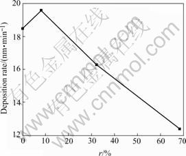
Fig.1 Deposition rate as function of N2 source gas flux ratio(r)
The deposition rate of the film increases a little at first and then decreases sharply with an increase of N2 source gas flux ratio(r). The reason for the increase is likely to be attributed to the decrease of F radicals etching effects. When N2 source gas flux increases, nevertheless the total gas flux holds the line, CF4 contents decrease in source gases and F radicals reduce in the chamber. For the ions�� etching to the films reduces, the deposition rate of the films increases. Subsequently, the reason of deposition rate decrease is related to the following aspects. Firstly, increase of N2 source gas flux ratio(r) enhances the density of nitrogenous radicals in the chamber. It will surely increase the collision probability of nitrogenous radicals and other radicals, thus more CN radicals are produced in the plasma radicals and the density of other radicals decreases. Moreover, CN radicals have no direct effect on growth of film[10]. Consequently the increase of N2 source gas flux ratio dilutes concentration of radicals of growing film, which results in the decrease of deposition rate. Secondly, with the increase of nitrogen source gas, abundant N2 and N ions exist in the chamber. Due to the bombardment of nitrogen ions, the weak bonds on the growing surfaces are broken and the ions combined unstably with films deviate from the films surface tie and go to the vacuum chamber. Furthermore, superfluous H or F ions will deviate from the films, which causes the deposition rate decrease. At the same time, it could eliminate some weak bonds and interstices and accordingly improve the quality of films.
We can use the variety ratio of the films thickness before and after annealing ?d/d(?d is the margin of the films thickness before and after annealing; d is the films thickness before annealing) to show the thermal stability of films. At different annealing temperatures, the effects of N2 source gas flux ratio on the thickness of the films are reported in Fig.2, which shows that the higher annealing temperature is, the more variety ratio of the films thickness is. In addition, after thermal annealing, films grown without N2 addition shows a distinct change. It demonstrates that the structure of films grown without N2 addition is loose and the thermal stability is poor. On the contrary, the variety ratio of the nitrogen doping a-C: F films thickness decreases after annealing. The ?d/d value of nitrogenous films (r=32%) is only 10% after 500 �� annealing. It is obvious that the thermal stability of a-C: F film is improved after nitrogen doping.
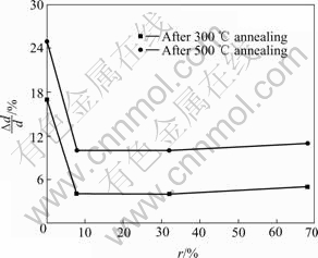
Fig.2 Thickness variety ratio of films versus r at different annealing temperatures
3.2 AFM analysis of films before and after annealing
In order to investigate the surface morphology the bidimensional (1��m��1��m) AFM images of the films grown with r=0% and r=32% before and after the thermal annealing are shown in Fig.3.
We can know the following characters from the AFM images. On the one hand, before thermal annealing, a-C��F films(r=0%) surface undulation is greater than those of a-C��F��N films(r=32%), and their peaks are 54.4 nm, 22.5 nm, respectively. Moreover, the films surface roughness minishes with increasing N2 source gas flux. The surface roughness of different films which deposited with r=0%, r=32%, r=68% are 7.180 nm, 2.057 nm, 1.685 nm, respectively. On the other hand, all film samples surface morphology gets improved after thermal annealing. Besides, the higher annealing temperature is, the smaller surface roughness is. For example, the surface roughness of films with N2 concentration values of 8% is 5.831 nm before annealing, and changes to 5.831 nm at 300 �� annealing, and drops to 2.882 nm at 500 �� annealing. This is because the increase of deposition temperature leads to an augment of transference rate of films surface atoms. The result of transference of surface atoms is the fluctuant vales and peaks of the surface are leveled off, thus the surface energy and roughness decrease.
The above conclusions all demonstrate that nitrogen doping and thermal annealing can make the films surface become more homogeneous and thus improve the films surface morphology.
3.3 Raman analysis of films
Raman spectrum is an effective means to investigate carbon materials structural and bonding mode. Different materials possess apparent different Micro-Raman spectra. Typical Raman spectra of the a-C��F films include the G band (1 575 cm��1) and the D (1 355 cm��1) band. The G band corresponds with aromatic rings and Olefin structure, while the D band associates with disorder degree in graphite and it only origins from the stretching vibrations mode of aromatic rings structure. Raman spectra of films deposited with different N2 source gases before and after 500 �� annealing are shown in Fig.3. In order to analyze the influence of flux ratio on Raman spectra, the spectra of Fig.3 are dealed with Gaussian fittings.
We obtained the films peak value of the G and D bands via Gaussian fittings, and then calculated integrated intensity ratio ID/IG between the D and G bands. Fig.4 shows ID/IG value as a function of N2 source gas flux ratio. As N2 source gas increases, the G peaks position shifts gradually to higher wave- numbers and ID/IG value increases. These all means sp2 carbon phase in films increases[11], namely,sp2/sp3 ratio ascends. That is, aromatic rings structure ratio augment and olefin structure ratio descends. According to the model of Beeman[12], peak position contains information of bond angel disorder and bond structure. Bond angel disorder and some four-coordinated bonds can make the D and G bands shift to the lower frequencies. Raman spectra shifting to the higher frequencies means that several bond angel disorders are eliminated and that the four-coordinated bonds (sp3) are broken and then translate to three-coordinated bonds (sp2). The reason of this translation is that the N atoms�� coordination number is 3, whereas C atoms�� coordination number is 4, thus the substitution of a C atoms with N atoms makes the average coordination number decrease. In addition, thermal annealing also make ID/IG value and sp2 clusters increase and relative content rings structure decrease. Due to thermal annealing, the sp3 clusters are changed to sp2 clusters, thus leads to increase of sp2 sites[13].
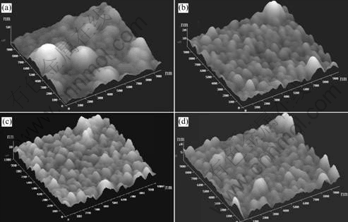
Fig.3 AFM images of films prepared under different conditions: (a) r=0%, before annealing; (b) r=32%, before annealing; (c)r=0%, after 300�� annealing; (d) r=32%, after 500 �� annealing
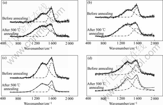
Fig.4 Raman spectra and Gaussian fittings of films deposited at different values of r: (a) r=0; (b) r=8%; (c) r=32%; (d) r=68%
It is well known that the polyimide is a compound polymer with the best thermal stability in practical applications in industry up to now. There are nitrogen atoms in polyimide which raise its thermal stability by forming hard carbon-to-nitrogen bond and imide ring. So people believe that ring structure can lead to argument of films thermal stability. ENDO and TATSUMI[14] and WANG et al[15] once pointed the relations between a-C��F film and its thermal stability. There must be more ring structures in the films in order to make the films thermal stability above 400 ��. Consequently, the increase of thermal stability partially attributes to the ring structures ratio increase after nitrogen doping. It is consistent with the conclusions of Refs.[11] and [16].
3.4 FTIR analysis of films
In order to investigate the effect of nitrogen doping on film structure, thus reveal the inherent reason of increasing thermal stability, the FTIR spectra of films before and after nitrogen doping are presented in Fig.5.
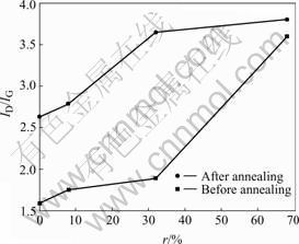
Fig.5 ID/IG ratio versus r before and after annealing
It can be seen that the FTIR spectra changs after nitrogen doping on a-C��F film, as follows: 1) after nitrogen doping, there appeared an absorption peak which was assigned to the C��N (2 200 cm��1) bond in the a-C��F��N films. This indicates that nitrogen element is not only doped effectively to the a-C��F films, but also formed chemical bonds with C atoms; 2) the absorption peaks which are assigned CFx(x=1, 2, 3) vibrations(950��1 500 cm��1) shift wholly to lower wavenumbers because of the decreasing of F element which possesses strong electronegative properties in the film; 3) the absorption peaks at 750��950 cm��1 become stronger after nitrogen doping. This demonstrates that there exists high concentration sp2 C[17], namely the quantity of carbon cross-linked structures increases. The thermal stability of a-C��F film lies in the quantity of carbon cross-linked structures in the film, thus the more cross-linked structures are, the higher thermal stability is; 4) the absorption peak at 1 570 cm��1 which correspond to Raman G band is not observed, but the absorption peak at 1 340 cm��1 corresponding to Raman D band become stronger after nitrogen doping. This illuminates that aromatic rings structure increases, thus correspond to the results of Raman spectra.

Fig.6 FTIR spectra of films deposited at variable N2 flux ratio
From all above, the obtained results demonstrates that the increase of thermal stability can be related to nitrogen incorporation which form the C��N chemical bonds of stable structure[11]. In addition, CF4 flux rate reduces with N2 flux rate increase, thus decomposable F atoms decrease in the chamber and the coupling effects between F and C atoms weaken. The cross- linked structure increased due to decrease of nitrogen content which can form only terminating bonds with carbon atoms and restrain cross-linked production, thus the thermal stability of films enhanced.
References
[1] Biloiu C, Biloiu I A. Amorphous fluorocarbon polymer films obtained by plasma enhanced chemical vapor deposition from perfluoro-octane vapor 1: Deposition, morphology, structural and chemical properties [J]. J Vac Sci Technol, 2000, A22(1): 13��19.
[2] ENDO K, Shinoda K, Tatsumi T. Plasma deposition of low-dielectric- constant fluorinated amorphous carbon [J]. J Appl Phys, 1999, 86(5): 2739��2745.
[3] ARIEL N, Eizenberg M, WANG Y, et al. Deposition temperature effect on thermal stability of fluorinated amorphous carbon films utilized as low-K dielectrics[J]. Materials Science in Semiconductor Processing, 2001, 4: 383��391.
[4] NING Zhao-yuan, CHANG Shan-hua, YANG Shen-dong. Influence of thermal annealing on bonding structure and dielectric properties of fluorinated amorphous carbon film[J]. Current Applied Physics, 2002(2): 439��443.
[5] Yi J W, Lee Y H, Farouk B. Annealing effects on structural and electrical properties of fluorinated amorphous carbon films deposited by plasma enhanced chemical vapor deposition[J]. Thin Solid Films, 2003, 423: 97��102.
[6] ENDO K, Tatsumi T. Nitrogen doped fluorinated amorphous carbon thin films grown by plasma enhanced chemical vapor deposition for low dielectric constant interlayer dielectrics[J]. Appl Phys Lett, 1996, 68: 3656��3658.
[7] Valentini l, Kenny J M. Influence of nitrogen and temperature on the plasma deposition of fluorinated amorphous carbon films[J]. J Vac Sci Technol, A20(4): 1210��1215.
[8] Yokomichi H, Masuda A. Effects of nitrogen incorporation on structural properties of fluorinated amorphous carbon films[J]. Journal of Non-Crystalline Solids, 2000, 271: 147��151.
[9] LIU Xiong-fei, XIAO Jian-rong, JIAN Xian-zhong, et al. Films prepared by PECVD[J]. Trans Nonferrous Met Soc China, 2004, 14(3): 426��429.
[10] ZHANG M, Nakayama Y, Miyazaki T, et al. Growth of amorphous hydrogenated carbon nitride films in radio-frequency plasma[J]. J Appl Phys, 1999, 85(5): 2904��2908.
[11] Valentini L, Kenny J M, Montereali R M, et al. Structural changes of fluorinated amorphous carbon films by nitrogen incorporation[J]. Materials Science in Semiconductor Processing, 2003, 5: 271��277.
[12] Beeman D, Silverman J, lynds R, ANDERSON M R. Modeling studies of amorphous carbon[J]. Phys Rev B, 1984, 30: 870��875.
[13] Bounouh Y, Theye M L, Dehbi-Aluoni A. Influence of �ШCbonded clusters on the electronic properties of diamond-like carbon films[J]. Diamond and Related Materials, 1993, 2: 259.
[14] Endo K, Tatsumi T. Amorphous carbon thin films containing benzene rings for use as low-dielectric-constant interlayer dielectrics[J]. Appl Phys Lett, 1997, 70: 2616��2618.
[15] WANG X, HARRIS H R, Bouldin K, GANGOPADHYA Y S, TEM H, STRATHMAN D D, WEST M. Structural properties of fluorinated amorphous carbon films [J]. J Appl Phys, 2000, 87(1): 621��624.
[16] Sanchez C M T, Maia da Costa M E H, Zamora R R M, PRIOLI R, FREIRE F L Jr. Nitrogen incorporation into hard fluorinated carbon films: nanoscale friction and structural modifications [J]. Diamond and Related Materials, 2004, 13: 1366��1370.
[17] Somnath B, Cardinaud C, Turban G. Spectroscopic determination of the structure of amorphous nitrogenated carbon films[J]. J Appl Phys, 1998, 83(8): 4491��4499.
Corresponding author: ZHOU Xin; Tel: +86-13874951284; E-mail: xzhou522@yahoo.com.cn
(Edited by LONG Huai-zhong)
