
Trans. Nonferrous Met. Soc. China 29(2019) 1560-1568
CFD modelling and optimization of oxygen supply mode in KIVCET smelting process
Jia-dong LI1, Ping ZHOU1, Zhou LIAO2, Li-yuan CHAI3, Chenn Q. ZHOU4, Ling ZHANG5
1. School of Energy Science and Engineering, Central South University, Changsha 410083, China;
2. Zhuzhou Smelter Group Company Limited, Zhuzhou 412004, China;
3. School of Metallurgy and Environment, Central South University, Changsha 410083, China;
4. Center for Innovation through Visualization and Simulation, Purdue University Northwest, 2200 169th Street, Hammond, IN 46323, USA;
5. Changsha Nonferrous Metallurgy Design and Research Institute Company Limited, Changsha 410019, China
Received 20 October 2018; accepted 17 May 2019
Abstract:
The influence of oxygen supply mode on the KIVCET (a Russian acronym for flash-cyclone-oxygen-electric-smelting) process was investigated using numerical simulation. The mass rate ratio (MRR) of central oxygen to lateral oxygen of the central jet distributor (CJD) burner was defined to express the oxygen supply mode, and the KIVCET process with an MRR ranging from 0.09 to 0.39 was simulated. The results show that there are four efficient reaction regions that correspond to four CJD burners. A higher central oxygen flow improves the mixing between particles and oxygen, thus enhancing reactions and shortening the reaction regions. However, a higher dust rate is induced due to the spread of the particle columns. The optimal MRR for a KIVCET furnace with a smelting capacity of 50000 kg/h is suggested to be 0.31. In this case, the chemical reactions associated with the feed are completed with an acceptable dust rate.
Key words:
KIVCET furnace; central jet distributor (CJD) burner; computational fluid dynamics (CFD); central oxygen; lateral oxygen; optimization;
1 Introduction
KIVCET (a Russian acronym for flash-cyclone-oxygen-electric-smelting) is used in many services as a modern, direct smelting process [1], in which oxygen, electric power, and fluid are efficiently combined [2]. KIVCET technology has been used in China for many years, and it enables the clean production and comprehensive utilization of waste slag in lead-zinc joint enterprises. The KIVCET furnace treats a dried mixture of lead concentrates, fluxes and Zn leaching residues [3]. The feed mixture and processed oxygen, including central and lateral oxygen, are fed into the smelting shaft through the corresponding passages of four top central jet distributor (CJD) burners, which are then ignited, oxidized and smelted in a suspended state. The molten mixture then passes through a coke checker that floats at bottom of the smelting shaft, causing a reduction in oxides, such as PbO, and the formation of lead bullion and slag. The lead/slag mixture travels under a partitioning wall to enter the electric furnace for phase disengagement, settling and the further reduction. The SO2-rich flue gas in the smelting shaft is hindered by the partitioning wall and escapes from the uptake shaft.
In the KIVCET process, the central oxygen flow of the CJD burner, which offers the lateral force only, has a great influence on the movement direction of feed particles [4]. A rational oxygen supply mode can help to achieve uniform mixing and complete reactions between particles and oxygen, and can constrain the accretion and corrosion of the water wall caused by high-temperature particle flow [5]. For instance, high central oxygen flow can enhance the horizontal movement of particles and improve their dispersion. However, more particles move toward the water wall, and the accretion and corrosion of the water wall can become severe due to particle-wall collision. If the central oxygen flow is too low, particles mainly move downward, causing poor dispersion and mixing, which is an adverse environment for chemical reactions in the furnace and will cause un-smelted material to pile up under the smelting shaft. Therefore, the oxygen supply mode of the CJD burner is significant in promoting the operation efficiency of the KIVCET furnace.
Experiments and numerical simulations have been widely used to evaluate the effect of the oxygen supply mode on copper [6-9] and nickel [10,11] smelting processes. Laboratory scale and pilot experiments can provide fundamental and accurate information of the smelting process, which is helpful for developing numerical models and mechanism studies, but the experimental research is expensive and time-consuming. With the development of computer technology, detailed physical fields and particle trajectories in flash smelting furnaces of copper/nickel can be obtained by using computational fluid dynamics (CFD) technology, leading to improved understanding [12], design and optimization of the CJD burner [13,14]. However, these results cannot be applied directly to the KIVCET furnace because there are differences in the structure and smelting mechanism between the KIVCET furnace and copper/nickel flash smelting furnaces [15-17]. Furthermore, few studies regarding the oxygen supply mode of CJD burners in the KIVCET furnace have been reported.
To improve the operation efficiency of the KIVCET furnace, it is necessary to explore the optimal oxygen supply mode of the CJD burner. In this work, a three- dimensional mathematical model has been developed to describe the KIVCET flash smelting process, and the optimal oxygen supply mode is obtained by numerically studying the effects of central and lateral oxygen flows on the smelting process.
2 Numerical methodology
2.1 Physical model
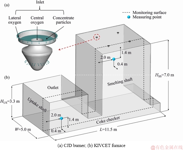
Fig. 1 Geometry of simulated KIVCET furnace
The KIVCET furnace with an average smelting capacity of 1200 t/d is taken as a simulated model, and its schematic diagram and dimensions are shown in Fig. 1. The computational domain includes the smelting shaft, CJD burner, coke checker, and uptake shaft. Four CJD burners are located on the roof of the smelting shaft, providing passages for the feed mixture and processed oxygen into the furnace. The lateral oxygen occupies the outermost annular channel and is vertically transported into the furnace. The central oxygen enters the burner from the central channel and further feeds into the furnace through 24 inclined holes to form dispersed oxygen. The channel for the feed particles is located between the two oxygen flows. The orientations of the particles that first flow freely downward are almost horizontal in an outward direction, caused by the effect of the curved surface in the burner and the dispersed oxygen. The geometry and smelting mechanism of the KIVCET furnace are further simplified as follows:
(1) The coke checker is assumed to be a stationary thin-wall, and the fluctuation that is induced by the impact of the smelting gas and products is ignored.
(2) The PbSO4 in the furnace charge is not considered because its content is less than 3% according to phase identification by X-ray diffraction (XRD) analysis.
(3) The PbSO4 formed by the oxidation reaction of PbS near burners is ignored because when the temperature exceeds 1033 K, PbSO4 tends to quickly decompose into PbO and O2 [18]; the lowest temperature of the KIVCET furnace occurs at the outlet of the uptake shaft, where the temperature ranges from 1523.15 to 1553.15 K [19].
A grid-independence validation with the grid numbers of 1.5��106, 2.3��106, and 3.1��106 is performed. The average gas temperature of the monitoring surface is used as the criterion of the mesh sensitivity. It is found that the result of the medium grid is similar to the fine mesh. Considering the computing cost and accuracy, the grid number of 2.3��106 is applied in this study (Fig. 2). During grid generation, a high degree of fineness is needed in regions where the structure is complex, such as the CJD burners and the area around the burners.
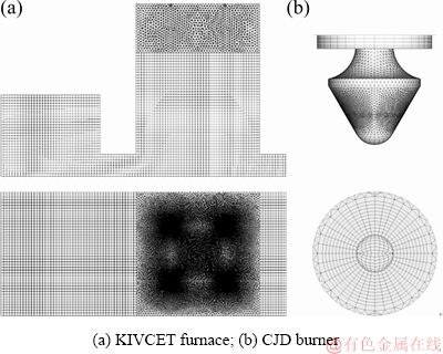
Fig. 2 Computational grid of simulated KIVCET furnace
2.2 Mathematical model
The processes of mass and heat transfer for both the gas and particle phases are considered by developing appropriate mathematical models. The Euler method is used to describe the gas phase, while the particle phase model is based on the Lagrangian method. The interactions between gas and concentrate particles are coupled through the source terms of the conservation equations of the gas phase.
2.2.1 Governing equations
The governing equation of the gas phase can be formulated in a general form:
 (1)
(1)
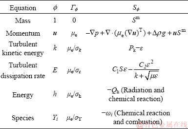
where  is a dependent variable, �� is the gas density, u is the velocity vector, �� is the diffusivity, and S is the source term generated by the interaction between gas and particle phases. The conservations of mass, momentum, energy, and species of the gas phase can be described by replacing the general terms �� and in Eq. (1) with the relevant variables listed in Table 1, where Sm is the mass source term, ��e is the effective viscosity, k is the turbulent kinetic energy, �� is the dissipation rate of the turbulent kinetic energy, Pk is the turbulent kinetic energy production, Qh is the heat source due to chemical reaction and radiation, and ��i is the source of gas species. The coupling method of the source terms is described in the following section. The turbulence of the gas phase is solved with the realizable k-�� model [20], which involves the solutions of the equations for turbulent kinetic energy and turbulent dissipation rate (Table 1). The values of the turbulence constants in this work are as
follows:
 C2=1.9,
 , ��k=1 and ����=1.2.
Table 1 Replaceable variables in general form of governing equation
2.2.2 Chemical reaction model
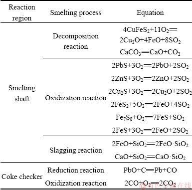
Based on previous work [21-23], the main smelting reactions involved in the decomposition, oxidization, slagging, and reduction of the feed particles are listed in Table 2.
(1) Gas phase chemical reaction model
The reaction rate of the gas phase, which is assumed to be controlled by turbulence, can be solved by the Eddy-Dissipation model (EDM) [24] as follows:
 (2)
(2)
 (3)
(3)
where ��i,r is the reaction rate of species i in reaction r,  is the stoichiometric coefficient for reactant i in reaction r, N is the number of species in reaction r, Mw,i is the relative molecular mass of species i, �� and �� are adjustable parameters equal to 4.0 and 0.5, respectively, YR is the mass fraction of a particular reactant R, YP is the mass fraction of the product specie P, and NR is the number of the chemical reaction.
Table 2 Chemical reactions used in simulation of KIVCET process
(2) Coke checker reaction model
The reduction reactions of lead and zinc oxide are mainly concentrated on the coke checker. In this work, the coke checker is considered as a wall surface reaction, the reaction rate of which is governed by both chemical kinetics and diffusion to and from the surface of the coke checker. On the reacting surface, the reaction rate is
 (4)
(4)
where Ji is the diffusion flux of the species i, n is the unit vector perpendicular to the surface of the coke checker, mdep is the net rate of mass deposition as a result of surface reactions, and Yi,wall is the mass fraction of species i on the wall.
The net mass transferred between the gas and particle phases is determined by
 (5)
(5)
where NI is the number of the species.
The energy source term from chemical reaction is
 (6)
(6)
where ��Hr is the reaction heat, which can be calculated based on specific enthalpy of formation at the given referenced temperature. The heat source due to radiation, Qrad, can be included in the energy equation in the form of the divergence of the radiative flux [25], and the P-1 radiation model is used to solve the radiation process [26].
2.2.3 Particle phase model
The particle phase is described by the Lagrangian method, and the interactions among particles are negligible because the volume fraction of the particle in the smelting furnace is less than 10%. The Rosin-Rammler distribution function is used to represent the particle size distribution. In addition, only drag force and body force are considered in this work.
The particle trajectory and temperature are determined by solving the momentum and energy equations as follows:
 (7)
(7)

 (8)
(8)
 (9)
(9)
 (10)
(10)
 (11)
(11)
where mp is the mass of a particle, up and u are the velocity vectors of the particle and gas phases, ��p and �� are the densities of the particle and gas phases, respectively, dp is the particle diameter, Tg and Tp are the temperatures of the gas and particle, respectively, Hreac is the heat released by the particle reaction, Ap is the surface area of particle, ��p is the particle emissivity, I is the local radiative heat flux, ��B is the Stefan-Boltzmann constant, Re is the Reynolds number, FD is the drag force, CD is the drag coefficient, and cp is the specific heat capacity of particles. �� is the gas thermal conductivity and Nu is the Nusselt number, evaluated using the correlation of RANZ and MARSHALL [27,28]:
 (12)
(12)
 (13)
(13)
where h is the heat transfer coefficient, Pr is the Prandtl number of the gas phase, ��g is the gas viscosity, and cp,g is the specific heat capacity of gas.
2.3 Simulation results and analysis
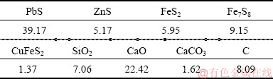
The smelting process in the KIVCET furnace is simulated by using ANSYS Fluent. Basic and operating parameters of the KIVCET furnace are determined by industrial measurements. The chemical composition of the feed mixture is given in Table 3.
Table 3 Chemical composition of feed mixture (wt.%)
The burner inlets of the oxygen and feed mixture are prescribed according to the measured flow rates. The outlet of the uptake shaft is set as a pressure outlet. The wall of the KIVCET furnace is assumed to be no-slip, and the temperatures of the furnace wall, burner wall, and coke checker are 1573, 1573, and 1523 K, respectively, based on the industrial measurements. The detailed boundary conditions in the basic test with the smelting capacity of 44670 kg/h are summarized in Table 4.
Considering the symmetry of the KIVCET furnace in its width direction, the simulation results presented in the following discussion are based on one monitoring surface, as shown in Fig. 1. The gas velocity distribution of the monitoring surface is shown in Fig. 3(a). The oxygen flow is found to expand after being into the smelting shaft, forming gas columns under burners. The gas columns slightly lean toward the centre of the smelting shaft due to pressure differences. Most of the gas exits the furnace from the outlet of the uptake shaft, whereas the remainder rebounds from the coke checker to the furnace to form recirculation zones, which can constrain the expansion of the gas columns and carry hot gases and particles from the bottom to the top of the shaft. The high-velocity region where the velocity exceeds 100 m/s is mainly located at the exit of the burners.
Table 4 Detailed description of boundary conditions of CJD burners
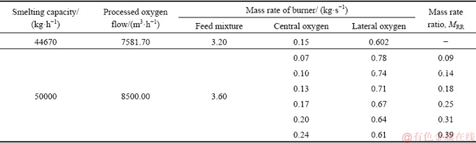
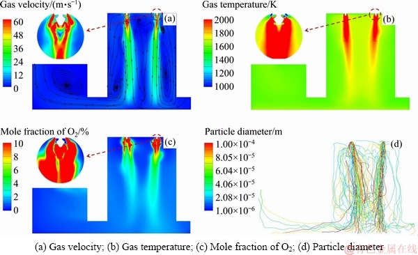
Fig. 3 Distribution of physical field
Figure 3(b) shows a contour map of the gas temperature of the monitoring surface. The high- temperature centralization regions under burners gradually become narrow due to the effect of recirculation zones. The maximum temperatures along the axes of the left and right burners are 2338.24 and 2395.33 K at a height of 6.5 m along the smelting shaft. The mole fraction of O2 rapidly decreases after leaving the burners and is the lowest at a height of approximately 6.6 m and then gradually increases. As shown in Figs. 3(b) and (c), a relatively uniform distribution of the gas temperature and the O2 concentration is apparent in the middle to lower part of the smelting shaft.
The particle trajectories, shown in Fig. 3(d), are also calculated. The particle columns that are often referred to as concentrate cones, with a high density of particles, are observed under four burners. The shapes of the particle columns are similar to those of the gas columns. However, there are a number of particles that travel outward beyond the gas columns. This effect is caused by the flow of central oxygen, which produces a lateral push on the particles to make them remove out of the gas columns. This is especially true for particles with diameters smaller than 5.05��10-5 m. Therefore, the flow field of the gas phase has an important influence on particle motion.
Although four efficient reaction regions with high temperature, oxygen consumption, and particle concentration are present under four CJD burners, the reactions in the remaining regions, such as the central region of the smelting shaft, are poor due to low particle population density and low oxygen concentration.
3 Model verification
The proposed numerical methodology should be verified by comparing the results to actual production data. The gas temperatures inside the smelting shaft are obtained by an industrial measurement. After the KIVCET furnace is run steadily, two S-type thermocouples are installed to measure the gas temperature near the furnace wall. The position of the measuring points is shown in Fig. 1. The operation condition of the KIVCET furnace is consistent with the initial simulation condition that is presented in Section 2.3.
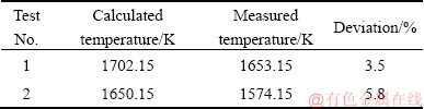
Table 5 shows the simulated and measured results for gas temperature. The calculated temperature is higher than the measured temperature because there is no consideration of the decomposition reaction for PbSO4 in the simulation, which is an endothermic reaction and has an impact on the reduction of the furnace temperature. The numerical model in this work is indicated to be correct and reliable.
Table 5 Comparison between calculated and measured gas temperatures
4 Optimization experiment
Rational matching of the central and lateral oxygen is significant when the smelting capacity increases. The effect of processed oxygen on the smelting process under different oxygen supply modes is simulated.
4.1 Oxygen supply mode
To express the oxygen supply mode, a parameter is first defined as the mass rate ratio (MRR) of the central oxygen to the lateral oxygen at a burner exit as
 (14)
(14)
where qc and ql are the mass rates of the central oxygen and the lateral oxygen, respectively. Then, numerical simulations with MRR from 0.09 to 0.39 are performed, as shown in Table 4, and the effects of the oxygen supply mode on flow, particle dispersion, and chemical reaction in the KIVCET furnace are studied. It is notable that the smelting capacity increases from 44670 to 50000 kg/h. The remaining boundary condition and initial condition are the same as those described in Section 2.3.
4.2 Results and discussion
The average distribution of temperature and O2 concentrations along the axes of four burners are shown in Fig. 4. A higher gas temperature and lower O2 concentration are apparent at a distance of approximately 0.5 m away from the roof of the smelting shaft as the MRR increases. At the tops of the four efficient reaction regions, increasing the central oxygen is beneficial for the oxidation reactions because a larger central oxygen flow can promote particle dispersion, as shown in Fig. 5(a), therefore improving the mixing between particles and oxygen. The reduction reaction in the coke checker can also be improved with an increase in central oxygen flow because more PbO is formed. However, the positive correlation between central oxygen flow and chemical reactions is no longer effective when the MRR is higher than 0.31. In the middle to lower part of the smelting shaft, the temperature decreases as the MRR increases. This is because under a larger central oxygen flow, most feed particles react with oxygen at a higher position due to good dispersion and mixing, ultimately shortening the reaction region, as shown in Fig. 5(b). In contrast, a smaller central oxygen flow lengthens the reaction regions.
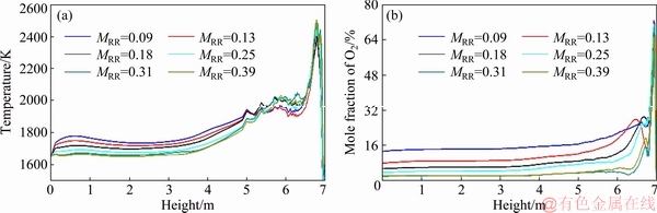
Fig. 4 Average distribution of temperature (a) and O2 concentration (b) along axes of four burners
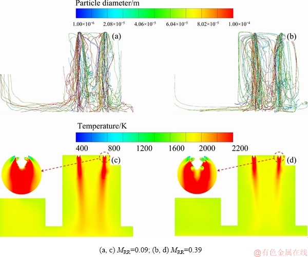
Fig. 5 Particle diameter (a, b) and temperature distribution (c, d)
Figure 6 presents the average distribution of the PbS concentration along the axes of four burners. For all cases, PbS is rapidly consumed after being fed into the furnace due to the oxidization reaction. Here, we assume that the oxidization reaction is finished when the PbS concentration is less than 0.002 kg/m3, i.e., 0.15% of the initial PbS concentration. For MRR=0.09, oxidization reactions continue until 0.20 m above the coke checker, stretching the reaction region, which can result in an incomplete reaction and more un-smelted material piled up under the smelting shaft. In contrast, increasing MRR to 0.39 leads to the termination of the oxidization reaction at a height of 4.31 m, which does not make full use of the smelting shaft. Therefore, MRR=0.31 is considered to be relatively reasonable because nearly half of the smelting shaft is in service and the extent of chemical reactions is acceptable.
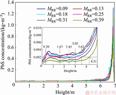
Fig. 6 Average distribution of PbS concentration along axes of four burners
The dust rate and SO2 content at the outlet are shown in Fig. 7. The dust rate, which is defined as the mass flux ratio of the dust to the feed mixture, increases with MRR, indicating that enhancing the central oxygen flow results in a higher dust yield. This is because the central oxygen flow enhances the irregular motion of the particles and makes them float inside the furnace instead of falling into the coke checker. These particles that are suspended in the smelting shaft are carried out of the uptake shaft by the gas flow, and finally become dust. A similar trend is found in the mole fraction of SO2, which demonstrates a larger central oxygen flow that corresponds to a higher desulfurization efficiency, but the variation is not obvious when the MRR exceeds 0.31.
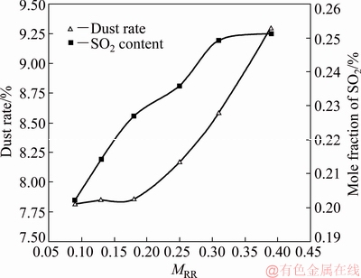
Fig. 7 Dust rate and SO2 content of outlet
In conclusion, changing the flow rate of the central and lateral oxygen is an effective approach to intensify the KIVCET process, in which problems such as incomplete chemical reactions, un-smelted material, and high dust rate should be solved. Therefore, the oxygen supply mode must carefully be optimized with the consideration of the gas flow, particle dispersion, and chemical reactions. In addition, the central reaction region is indispensable for intensifying the KIVCET process, and the effective utilization of this area should be promoted.
5 Conclusions
(1) A three-dimensional mathematical model for the KIVCET process is developed, and the model is validated by a comparison between simulated and industrial measured data.
(2) Four efficient reaction regions are found to correspond to four CJD burners, and the central region of the smelting shaft, with a lower temperature and particle concentration, is underutilized.
(3) Increasing the central oxygen flow causes more particles to exit the particle columns, promoting the mixing between particles and oxygen and resulting in better chemical reactions and shorter reaction regions.
(4) For a KIVCET furnace with a smelting capacity of 50000 kg/h, MRR=0.31 is considered to be the optimal oxygen supply mode because the chemical reactions in this case are completed with an acceptable dust rate.
References
[1] ZAHRANI E M, ALFANTAZI A M. Molten salt induced corrosion of Inconel 625 superalloy in PbSO4-Pb3O4-PbCl2-Fe2O3-ZnO environment [J]. Corrosion Science, 2012, 65: 340-359.
[2] SLOVIKOVSKII V V, GULYAEVA A V. Effective linings for KIVCET furnaces [J]. Refractories and Industrial Ceramics, 2014, 54(5): 350-352.
[3] GREGUREK D, REINHARTER K, MAJCENOVIC C, WENZL C, SPANRING A. Overview of wear phenomena in lead processing furnaces [J]. Journal of the European Ceramic Society, 2015, 35(6): 1683-1698.
[4] ZHOU Jun, ZHOU Jie-min, CHEN Zhuo, MAO Yong-ning. Influence analysis of air flow momentum on concentrate dispersion and combustion in copper flash smelting furnace by CFD simulation [J]. JOM, 2014, 66(9): 1629-1637.
[5] MEI Chi, PENG Xiao-qi, ZHOU Ping, ZHOU Jie-min, ZHOU Nai-jun. Simulation and optimization of furnaces and kilns for nonferrous metallurgical engineering [M]. Berlin: Springer-Verlag, 2010.
[6] HIGGINS D R, GRAY N B, DAVIDSON M R. Simulating particle agglomeration in the flash smelting reaction shaft [J]. Minerals Engineering, 2009, 22(14): 1251-1265.
[7] CHEN Hong-rong, MEI Chi, XIE Kai, LI Xing-fen, ZHOU Jun, WANG Xiao-hua, GE Ze-ling. Operation optimization of concentrate burner in copper flash smelting furnace [J]. Transactions of Nonferrous Metals Society of China, 2004, 14(3): 631-636.
[8] WANG Qin-meng, GUO Xue-yi, WANG Song-song, LIAO Li-le, TIAN Qing-hua. Multiphase equilibrium modelling of oxygen bottom-blown copper smelting process [J]. Transactions of Nonferrous Metals Society of China, 2017, 27(11): 2503-2511.
[9] WANG Qin-meng, GUO Xue-yi, TIAN Qing-hua. Copper smelting mechanism in oxygen bottom-blown furnace [J]. Transactions of Nonferrous Metals Society of China, 2017, 27(4): 946-953.
[10] KOH P T L, JORGENSEN F R A, ELLIOT B J. Solids falling in flash furnace burner concentrate chutes [J]. International Journal of Mineral Processing, 2007, 83(3-4): 81-88.
[11] SUTALO I D, JORGENSEN F R A, GRAY N B. Experimental and mathematical investigation of the fluid flow inside and below a 1/4 scale air model of a flash smelting burner [J]. Metallurgical and Materials Transactions B, 1998, 29(5): 993-1006.
[12] ZHOU Jun, CHEN Zhuo, ZHOU Ping, YU Jian-ping, LIU Ai-ming. Numerical simulation of flow characteristics in settler of flash furnace [J]. Transactions of Nonferrous Metals Society of China, 2012, 22(6): 1517-1525.
[13] SOLNORDAL C B, JORGENSEN F R A, KOH P T L, HUNT A. CFD modelling of the flow and reactions in the Olympic Dam flash furnace smelter reaction shaft [J]. Applied Mathematical Modelling, 2006, 30(11): 1310-1325.
[14] NIJDAM J J, LANGRISH T A G, FLETCHER D F. Assessment of an eulerian CFD model for prediction of dilute droplet dispersion in a turbulent jet [J]. Applied Mathematical Modelling, 2008, 32(12): 2686-2705.
[15] KOJO I, STORCH H. Copper production with Outokumpu flash smelting: an update [C]// KONGOLI F, REDDY R G. Sohn international symposium: Advanced processing of metals and materials. volume 8-International symposium on sulfide smelting. Warrendale, PA: The Minerals, Metals & Materials Society, 2006: 225-238.
[16] MELCHER D L G, MULLER D L E, WEIGEL D L H. The KIVCET cyclone smelting process for impure copper concentrates [J]. JOM, 1976, 28(7): 4-8.
[17] LAKSHMANAN V I, RAMACHANDRAN R. Innovative case study processes in extractive metallurgy [M]. Cham: Springer International Publishing, 2016.
[18] MALINOWSKI C, MALINOWSKA K, MALECKI S. Analysis of the chemical processes occurring in the system PbSO4-ZnS [J]. Thermochimica Acta, 1996, 275(1): 117-130.
[19] ZHANG Le-ru. Modern lead metallurgy [M]. Changsha: Central South University Press, 2013. (in Chinese)
[20] LATEB M, MASSON C, STATHOPOULOS T, BEDARD C. Comparison of various types of k-�� models for pollutant emissions around a two-building configuration [J]. Journal of Wind Engineering and Industrial Aerodynamics, 2013, 115: 9-21.
[21] LI Yan-chun, LIU Zhi-lou, LIU Hui, PENG Bing. Clean strengthening reduction of lead and zinc from smelting waste slag by iron oxide [J]. Journal of Cleaner Production, 2017, 143: 311-318.
[22] BAI Lu, XIE Ming-hui, ZHANG Yue, QIAO Qi. Pollution prevention and control measures for the bottom blowing furnace of a lead-smelting process, based on a mathematical model and simulation [J]. Journal of Cleaner Production, 2017, 159: 432-445.
[23] WANG Jin-liang, WEN Xiao-chun, ZHANG Chuan-fu. Thermodynamic model of lead oxide activity in PbO-CaO-SiO2- FeO-Fe2O3 slag system [J]. Transactions of Nonferrous Metals Society of China, 2015, 25(5): 1633-1639.
[24] HALOUANE Y, DEHBI A. CFD simulations of premixed hydrogen combustion using the eddy dissipation and the turbulent flame closure models [J]. International Journal of Hydrogen Energy, 2017, 42(34): 21990-22004.
[25] YANG Xin, CLEMENTS A, SZUHANSZKI J, HUANG Xiao-hong, FARIAS MOGUEL O, LI Jia, GIBBINS J, LIU Zhao-hui, ZHENG Chu-guang, INGHAM D, MA Lin, NIMMO B, POURKASHANIAN M. Prediction of the radiative heat transfer in small and large scale oxy-coal furnaces [J]. Applied Energy, 2018, 211: 523-537.
[26] CHENG Ping. Two-dimensional radiating gas flow by a moment method [J]. AIAA Journal, 1964, 2: 1662-1664.
[27] RANZ W E, MARSHALL W R. Evaporation from drops: Part I [J]. Chemical Engineering Progress, 1952, 48: 141-146.
[28] RANZ W E, MARSHALL W R. Evaporation from drops: Part II [J]. Chemical Engineering Progress, 1952, 48: 173-180.
�����������������й�����ʽ��CFDģ�����Ż�
��Ҷ�1���� Ƽ1���� ��2������Ԫ3��Chenn Q. ZHOU4���� ��5
1. ���ϴ�ѧ ��Դ��ѧ�빤��ѧԺ����ɳ 410083��
2. ����ұ�����Źɷ�����˾������ 412004��
3. ���ϴ�ѧ ұ���뻷��ѧԺ����ɳ 410083��
4. Center for Innovation through Visualization and Simulation, Purdue University Northwest, 2200 169th Street, Hammond, IN 46323, USA;
5. ��ɳ��ɫұ������о�Ժ����˾����ɳ 410019
ժ Ҫ��ͨ����ֵģ���о�������ʽ�Ի��������������̵�Ӱ�졣��������������������������������������ȱ�ʾ������ʽ��ģ��������������0.09~0.39��Χ�ڵĻ�������¯�������̡����������4������������������·�����Ϊ��Ч��Ӧ���������������������Ը��ƿ���������Ļ��״�����Ӷ��ٽ���ѧ��Ӧ�Ľ��У�ͬʱ�����̸�Ч��Ӧ�������ǣ����������¿������ķ�ɢ��ʹ�̳������ӡ�������������Ϊ50000 kg/h�Ļ�������¯�������ŵĹ�����ʽΪ����������ȡ0.31���ڸù����£�¯�ϵĻ�ѧ��Ӧ���Գ�ֽ��У�ͬʱҲ��֤�ϵ͵��̳��ʡ�
�ؼ��ʣ���������¯�����������ɢ���죻����������ѧ�������������������Ż�
(Edited by Bing YANG)
Foundation item: Project (61621062) supported by the Foundation for Innovative Research Groups of the National Natural Science Foundation of China
Corresponding author: Ping ZHOU; Tel: +86-13975804856; E-mail: zhoup@csu.edu.cn
DOI: 10.1016/S1003-6326(19)65063-6
Abstract: The influence of oxygen supply mode on the KIVCET (a Russian acronym for flash-cyclone-oxygen-electric-smelting) process was investigated using numerical simulation. The mass rate ratio (MRR) of central oxygen to lateral oxygen of the central jet distributor (CJD) burner was defined to express the oxygen supply mode, and the KIVCET process with an MRR ranging from 0.09 to 0.39 was simulated. The results show that there are four efficient reaction regions that correspond to four CJD burners. A higher central oxygen flow improves the mixing between particles and oxygen, thus enhancing reactions and shortening the reaction regions. However, a higher dust rate is induced due to the spread of the particle columns. The optimal MRR for a KIVCET furnace with a smelting capacity of 50000 kg/h is suggested to be 0.31. In this case, the chemical reactions associated with the feed are completed with an acceptable dust rate.
