
J. Cent. South Univ. (2012) 19: 1753-1763
DOI: 10.1007/s11771-012-1202-3![]()
Design parameter optimization of beam foundation on soft soil layer with nonlinear finite element
WEI Hong-wei(���)1, WU Ya-zhong(������)2, YU Ze-hong(�����)1
1. School of Civil Engineering, Central South University, Changsha 410075, China;
2. Transportation Department of Hunan Province, Changsha 410000, China
? Central South University Press and Springer-Verlag Berlin Heidelberg 2012
Abstract:
Finite element method was performed to investigate the influences of beam stiffness, foundation width and cushion thickness on the bearing capacity of beam foundation on underlying weak laminated clay. The comparison between numerical results and results from field test including plate-bearing test and foundation settlement observation shows reasonable agreement. According to the numerical results, the beam width, length, cross section and cushion thickness were optimized. The results show that the stresses in subgrade soil decrease greatly with increasing the cushion thickness and width of foundation. However, the foundation settlement and influencing depth of displacement also increase correspondingly under conditions of relatively thinner cushion thickness. For the foundations on underlying weak layer, increasing foundation width merely might be inadequate for improving the bearing capacity, and the appropriate width and cushion thickness depend on the response of subgrade. A comparison between rigid and flexible beams was also discussed. The influence of a flexible beam foundation on subgrade is relatively smaller under the same loading conditions, and the flexible beam foundation appears more adaptable to various subgrades. The proposed flexible beam foundation was adopted in engineering. According to the calculation results, beam width of 2.4 m and cushion thickness of 0.8 m are proposed, and a flexible beam foundation is applied in the optimized design, which is confirmed reasonable by the actual engineering.
Key words:
beam foundation; design optimization; soft soil; soil-beam interaction; nonlinear analysis��
1 Introduction
Bearing capacity of foundation was predicted currently by the depth of plastic zone under foundation, Terzaghi theoretical equations and specification methods. However, these calculation results generally tended to be too conservative relatively. Determination of the bearing capacity directly by the static load test resulting in the field was believed to be reliable, but its representative was inadequate obviously. Unfortunately, in most designs, the permissible bearing capacity values were still determined by the minimal characteristic values of the field or laboratory test results. Since the homogeneous soils were very seldom, the physical properties and distributions of soil changed greatly at random, and led to different foundation failure modes. Consequently, the application of finite element method to calculate the whole foundation and combining the calculation results with test results, might be more feasible to put forward the reliable capacity evaluation for engineering.
Finite element method are adopted widely in slope stability and earth pressure analyses, to calculate stresses and strains in soil structures under working conditions [1-6], and a great number of useful results had been obtained. In contrast, such analyses were applied in fewer literatures in prediction of foundation bearing capacity [7-12]. A probabilistic study on the bearing capacity of a rough rigid strip footing on a weightless cohesive soil was carried out by GRIFFITHS and GORDON [7]. In this work, a nonlinear finite element method combined with random field theory in conjunction with a Monte Carlo model had been used to investigate the influence of the spatial variation of shear strength on the mean bearing capacity, and the effect of rough and smooth footing on failure mechanisms. KUMAR [8] employed finite elements to study the variation of the bearing capacity factor with changes in friction angle of the footing/soil interface, and the demonstrated assumption of a perfectly rough footing would lead to an unsafe prediction of the collapse load. Other similar studies were also carried out by some researchers [13-22].
In this work, the foundation-track beam system finite element model was set up to analyze the bearing capacity of beam foundation, and the interaction between beam foundations and subgrade. The six-noded triangle was used to model foundation soil, and beam element was incorporated to model beam foundation. A four-noded quadrilateral element developed by Goodman et al [3, 13-15] was adopted in order to model the interface between beam and foundation soil, and a viscoplastic algorithm and the Tresca yield criterion was applied in analysis. According to calculation results, design parameters optimization of the beam foundation on weak soil layer was carried out including cushion thickness, width of foundation and beam stiffness, and the influences of various parameters on subgrade were also discussed. The comparison of calculation results with the field test results from plate-bearing test, foundation settlement observation, and results from related literatures was conducted.
2 Engineer outline and design information
2.1 Engineering background
The box girder prefabricated plant of Tai-Zhong-Yin Railway Engineering is situated in Qingxu County of Shanxi Province, China. The foundation soil layers in 30 m depth range from top to bottom are: the late Quaternary Holocene alluvium layer, demarcated at the bottom of the second silty clay layer; the early or middle Quaternary Holocene alluvium layer, demarcated at the bottom of the fourth silty clay layer; the Quaternary Pleistocene alluvium layers.
The proposed buildings rested heavily on the first silt and silty clay layer, and silt and silty sand layer acted as the first underlying layer, whose rock characteristics varied greatly in the horizontal direction. According to soil distribution and the variability analysis of physical and mechanical index, the building foundations were inhomogeneous ground, whose hard shell layer was 1.5-3.0 m thick, and the underlying weak laminated arch clay appeared mud and plastic flow, with thickness of 2.5-6.0 m.
Under this field conditions, a large-scale gantry crane system of lifting weight of 180 t and self-weight of 130 t was planned to be erected, with two arranged in parallel within 10 m. The preliminary design and subgrade treatment are shown in Fig. 1. The width of beam foundation was 2.6 m with 0.1 m-thick concrete and 0.5 m-thick crushed stone cushions, and the subgrade treatment applied 8 m-long gravel piles.
With poor drainage conditions and constraints by local laws and regulations that the field must be rehabilitated to cultivate after the completion of engineering, the application of gravel piles was infeasible, and the bearing capacity and stability of the natural soil needed reliable safety evaluation. Meanwhile, an alternative foundation treatment scheme and corresponding structure design of track beam should be put forward prudently. The definition of problem can be illustrated in Fig. 2.
2.2 Soil layer distribution, physical and mechanical properties
According to the geological prospecting report, the formations of subgrade soil layers were as follows:
Layer 1: Silty clay. The thickness is 0.8-2.10 m, with the average thickness of 1.62 m; SPT (standard penetration test) blow counts are in the range of 2.0-4.0, with an average of 3.0. Compression coefficient a1-2 is in the range of 0.23-0.63 MPa-1, with an average of 0.40 MPa-1;
Layer 2: Silt and silty sand. The thickness is 1.9- 6.60 m, with the average thickness of 4.15 m; SPT blow counts are in the range of 1.0-4.5, with an average of 2.2. Compression coefficient a1-2 is in the range of 0.12- 0.40 MPa-1, with an average of 0.20 MPa-1;
Layer 3: Firstly, silt. The thickness is 1.1-8.70 m, with the average thickness of 5.71 m; compression coefficient a1-2 is in the range of 0.10-0.31 MPa-1, with an average of 0.16 MPa-1; SPT blow counts are in the range of 4.0-12.0, with an averaging of 6.4. Secondly, silty sand. The thickness is 1.1-11.1 m, with an average thickness of 4.88 m; SPT blow counts are in the range of 6.0-16.0, with an average of 12.5.
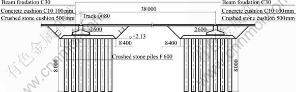
Fig. 1 Preliminary design and subgrade treatment (Unit: mm)
Layer 4: Silty clay. The thickness is 3.6-8.0 m, with the average thickness of 5.76 m; compression coefficient a1-2 is in the range of 0.14-0.65 MPa-1, with an average of 0.43 MPa-1; SPT blow count is in the range of 6.0-16.0, with an average of 9.9.
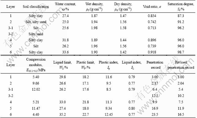
Soil physical and mechanical properties are listed in Table 1.
2.3 Standard penetration test results
Eighteen geotechnical drilling exploration points were carried out in the field, in which nine holes were used in soil sampling and others were used in SPT. The drilling depths were 15.0-30.0 m with a cumulative depth of 360 m. 106 undisturbed soil specimens and 67 disturbed soil specimens were obtained with heavy hammer method, and 118 standard penetration tests were run on with drop hammer method.
A SH-30 engineering driller was used in drilling exploration. Dry drilling and drilling with casing coupling were used, respectively, above and below ground water elevation. The test procedure was complied with exploration standard specification for geotechnical engineering (GB 50021��2001) and soil test method standard (GB/T 50123��1999).
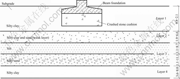
Fig. 2 Sketch of problem (Unit: m)
Table 1 Soil physical and mechanical properties
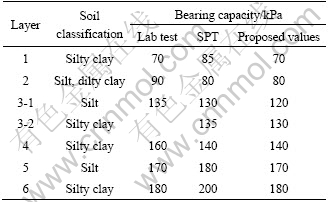
Based on laboratory soil tests and standard penetration test results, the empirical formula associated with the regional building experience was used to evaluate the bearing capacity of soil layers. The evaluation results are listed in Table 2.
Table 2 Characteristic bearing capacity values of soil layers
Considering the lifting weight and self-weight of the gantry crane system, the basement pressure of gantry crane was about 150 kPa. Under natural field conditions, the calculated bearing capacity values varying with various foundation embedded depths (reversed by depth) are listed in Table 3.
Supposing the embedded depth of foundation was 3.0 m, the second silt and silty clay layer would act as the bearing layer, and the natural field would meet the loading requirements of the upper structure. The raft foundation was applicable. As a result of heterogeneous distributions in longitudinal and vertical directions, the ground treatment should be still required.
2.4 Static bearing capacity test results
The bearing capacity tests were divided into three groups of A, B and C, and three points with a distance of about 2-3 m were measured in each group. Groups A and B were situated in the vicinity of the 6th and 9th holes drilled previously, which were limited in the scope of the gantry crane foundation (the width of 5 m considered). While group C was arranged between the 10th and 11th holes, which was limited under beam deposit (distance between center lines of 3.5 m). Three groups spanned the space of 400 m.
The distribution of static bearing capacity test is shown in Fig. 3.
Two working situations were simulated in bearing capacity tests. The first was in accordance with the situation that excavating 1 m in the original ground, then filling 70-80 cm, and compacting to about thickness of 50 cm (the data calculated by 1.0 m high-beam). For group A, the original ground elevation was +758.856 m, after excavation and backfill compaction, the south elevation was +757.932 m, and the north was +757.995 m; For group B, the original ground elevation was +758.840 m, and after excavation and backfill compaction, the south and north elevations were +758.343 and +758.327 m, respectively. In the second situation (group C), tests were run on after roller compaction. The south elevations of original and rolling were 758.983 and 758.979 m, and the north were 758.905 and 758.775 m, respectively. The request of the bearing capacity characteristics value must be more than 250 kPa after the subgrade treatment.
Table 3 Natural field bearing capacity revised with embedded depth
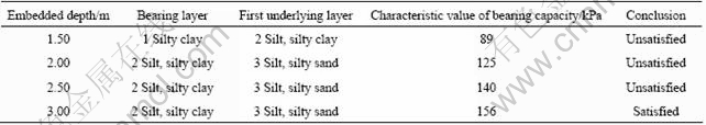

Fig. 3 Static bearing capacity test distribution (Unit: m)
Table 4 Static bearing capacity tests results
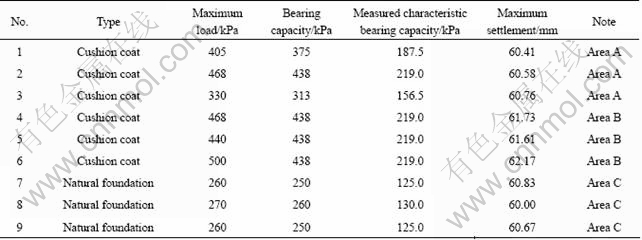
The bearing capacity tests of filling cushion layers had three groups in area A and the other three in area B. The bearing capacity characteristics value was 156.5 kPa for A, and 219 kPa for B. Both could not meet design requirements (design characteristic values no less than 250 kPa).
Test-bearing capacity characteristic value:
Area A: No.1, 187.5 kPa; No.2, 219 kPa; No.3, 156.5 kPa; the area bearing capacity characteristic value, 156.5 kPa.
Area B: No.4, 219 kPa; No.5, 219 kPa; No.6, 219 kPa; the bearing capacity characteristics value, 219 kPa.
Area C: No.7, 125 kPa; No.8, 130 kPa; No.9, 125 kPa; the bearing capacity characteristics value, 125 kPa, which could not satisfy design requirements.
3 Design parameters optimization of beam foundation
3.1 Finite element method
In current methods to estimate the bearing capacity of foundation, two idealized situations were usually involved: perfectly smooth or perfectly rough footings, which means no horizontal shear stresses allowed at the foundation base or no relative horizontal sliding between foundation and soil. In reality, beam foundations were usually constructed by pouring concrete directly on underlying soil, and the beam/soil interface was rough enough to resist the slip tendency. In finite element analyses, beam foundation was assumed to be extensible, satisfying no slip and compatibility conditions at the interface between the beam foundation and the neighboring soil.
Soil and beam foundation were discretized to viscoplastic plate units and beam units, respectively. The six-noded linear strain triangle was used to model foundation soil. This element was capable of correctly modeling collapse behavior under undrained conditions for plane stain problems. The bearing capacity analyses were carried out by finite element method using a viscoplastic algorithm and the elastic-perfectly plastic Tresca yield criterion.
A four-noded quadrilateral element developed by Goodman et al [3, 13-15] was adopted in order to model the interface between beam and subgrade soil. This element had been used to simulate the interface between soil and geosynthetics in analysis of reinforced embankment approach bridge abutment by YU and HAN et al [13]. The maximum shear resistance of this element was equal to soil shear strength.
In undrained conditions, a large volume of shear modulus should be used as possible in analysis, but the parameters were too large, and the numerical problem might occur. The bulk modulus of 5.6?105 kPa was found to be satisfactory. To limit the relative displacements prior to slip and normal to interface, the stiffness parameters were set to high values, ks=6.5? 103 kPa/m, and kn=106 kPa/m. The beam stiffness of 2.05?107 kPa/m was used, and adjacent soil strength was chosen by test information, as summarized in Table 5.
The boundary conditions were given as vertical rollers on the left and right boundaries, full fixity at the base, and free boundary at the rest. The calculation width was adopted to be 5 times of beam width, and the calculation depth was 10 times of beam height.
Table 5 Soil strength parameters

3.2 Stress in subgrade soil and foundation settlement
A gravel cushion thickness of 0.5 m was proposed tentatively, entering the calculation parameters to calculate stresses in subgrade soil and displacement of beam foundation with various widths under upper loads of 28 t.
Under beam foundation of 1.8 m in width, the calculation vertical stress in subgrade was 236 kPa, the vertical displacement of foundation was 6.5 cm, and the plastic shear zone went completely through the subgrade, as illustrated in Fig. 4. Increasing the beam foundation width to 2.8 m, the calculated stress was reduced to 146 kPa, while the vertical displacement increased to 7.9 cm. The plastic failure zone also went completely through the foundation, as shown in Fig. 5. It could be seen that the stress in subgrade soil decreased greatly with increasing the width of foundation. However, the foundation settlement and influencing depth of displacement would also increase correspondingly in such subgrade with soft layers. Consequently, increasing foundation width merely might be inadequate for improving the bearing capacity, especially in the foundations on underlying weak laminated arch clay.
Increasing cushion thickness and reducing the foundation width progressively were applied to calculating the various stresses in subgrade soil and displacements of beam foundations. When the cushion thickness and beam width increased up to 0.8 m and decreased to 2.4 m, respectively, under load of 28 t, only some of the plastic deformation emerged in subgrade soil, as illustrated in Fig. 6. The calculated vertical stress was 132 kPa, the displacement was 4.7 cm, and the bearing capacity was improved. The vertical stress state cloud under beam cross-section, as shown in Fig. 7. The design of beam foundation-subgrade system appeared reasonable relatively.
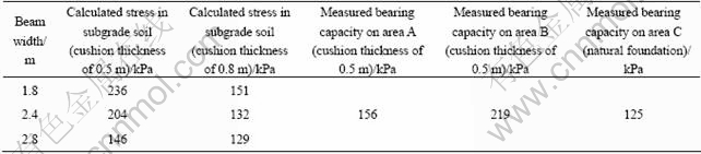
3.3 Comparison of calculated and measured results
As to the crushed stone cushion thickness of 0.5 m and track beam width of 1.8, 2.4 and 2.8 m, the calculated stresses in subgrade soils were 236, 204, 146 kPa, respectively, less than or close to the measured bearing capacity value of 219 kPa in area B, but greater or close to the measured value of 156 kPa in area A, as given in Table 6.
Such consequences were mainly attributed to two facts as follows:
Area A was situated in the vicinity of the 6th hole. The original geological cross-section showed that the Layer 1 was silty clay with the thickness of 1.5 m, and SPT blow count was in the range of 2.0-4.0 with an average of 3.0. The compression coefficient fluctuated in the range of 0.23-0.63 MPa-1, with an average of 0.40 MPa-1. Layer 2 was silt, silty sand, with the thickness of 5.0 m; SPT blow counts were in the range of 1.0-4.5, with an average of 2.2; compression coefficient changed in the range of 0.12-0.40 MPa-1, with an average of 0.20 MPa-1. The soil is classified in typical weak laminated arch clay.
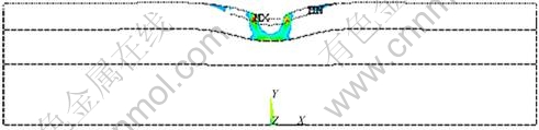
Fig. 4 Subgrade plastic failure zone under 1.8 m width beam (cushion thickness of 0.5 m)
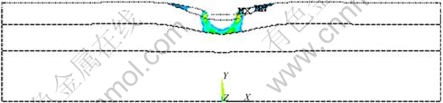
Fig. 5 Subgrade plastic failure zone under 2.8 m width beam (cushion thickness of 0.5 m)
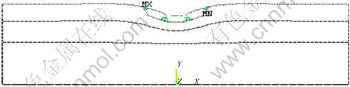
Fig. 6 Subgrade plastic deformation under 2.4 m width beam (cushion thickness of 0.8 m)
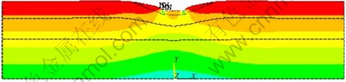
Fig. 7 Vertical stress state in subgrade under 2.4 m width beam (cushion thickness of 0.8 m)
Table 6 Calculated and measured values of bearing capacity
Area B in the vicinity of the previously drilled 9th hole. The original geological cross-section showed that Layer 1 was silty clay layer, with the thickness is of 1.3 m; Layer 2 was silt and silty clay, with the thickness is of 4.3 m. The observed laminated soft soil appeared completely plastic flow in field. Due to the weak soil thickness was increased up to 1.9-6.60 m, with the average of 4.15 m, the measured bearing capacities in areas A and B were influenced greatly by the second layer.
The calculated results could be accepted in the light of engineering accuracy. The comparisons of the measured data and calculation results also showed that the FEM calculation model and method in the work were acceptable.
Soil column charts in the vicinity of the 6th and 9th holes are shown in Figs. 8 and 9.
3.4 Determination of foundation width and cushion thickness
Considering heterogeneity of the soil mechanical properties in the vertical and horizontal directions, the 2.4 m-wide track beam and 0.8 m-thick crushed stone cushion were used in engineering. The calculated stress of 132 kPa by finite element was still less than the measured stress of 156 kPa in area A. The project had been put into operation since March, 2007, and the measured settlements were within 0.8-2.1 cm, less than the calculated displacement of 4.7 cm. This showed that track beam foundation did not approach the ultimate bearing state, and the alternative design of track beam width and ground treatment programs were reasonable. The calculated displacement values appeared slightly higher than the measured one, mainly due to the application of higher interfacial parameters between the beam foundation and subgrade soil, as previously described that the foundation was rough enough. For a larger roughness, the influences of foundation on settlement tended to be greater, and the designs in accordance with such calculation results would benefit the structure security, which met well with the results from Refs. [4, 8, 10]. The alternative design of track beam width and ground treatment are shown in Fig. 10.
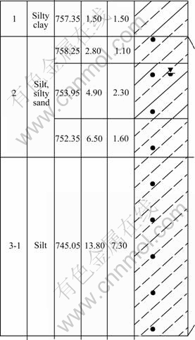
Fig. 8 Soil column chart in 6th hole (Area A)
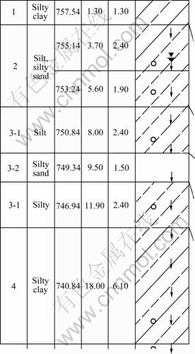
Fig. 9 Soil column chart in 9th hole (area B)
3.5 Determination of foundation length and cross- section
Under the same conditions of upper load of 28 t, beam width of 2.4 m and cushion thickness of 0.8 m, beam foundations would still appear different characteristics with various lengths, and the failure modes of subgrade soil differed correspondingly.
Constrained by the construction conditions (template length, etc.), the 21 m-wide poured-in-place concrete track beam was adopted in engineering, other beam section parameters were given in Table 7, and subgrade soil modulus of 5��104 kPa was used.
According to the classical structure principle of beam foundation, for a plate problem, the characteristics length of beam can be expressed as
![]() (1)
(1)
where EI means section stiffness, and E0 means subgrade modulus.
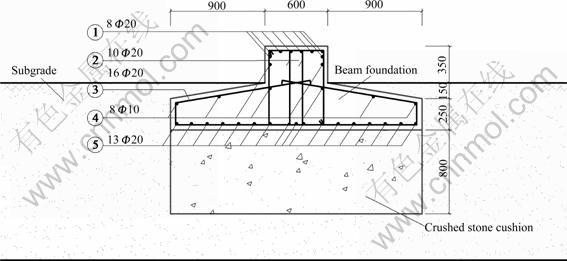
Fig. 10 Alterative design and subgrade treatment (Unit: mm)
Table 7 Basic parameters of track beam
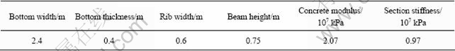
Substitute Eq. (1) with the parameters in Table 7, calculated characteristic length of beam was L=9.18 m.
The flexibility coefficient t of beam can be expressed as
![]() (2)
(2)
where l means half length of beam.
The beams are generally divided into two categories including short beams and long ones with 0��t��10 and t>10, respectively. When the flexibility coefficient t<1, it can be regarded as an absolute rigid beam.
For a single-track beam with 21 m in width, the calculated flexibility coefficient t1 is 4.7/m, and it belongs to a rigid beam.
When the crane load is applied on the beam edges, the plastic shear zone in subgrade soil goes through the whole calculation depth, as shown in Fig. 11. The bearing capacity of subgrade could not satisfy the design requirement. The track beam bending moment is shown in Fig. 12. The maximum positive moment is 1 276 kN��m, and the negative moment is 341.8 kN��m.
Dowelled track beams with 4 beams of 21 m-long were proposed tentatively in order to change the beam foundation characteristics. The calculated flexibility coefficient t2 was 300.6 m-1, and it turned into a flexible beam. In addition, to ensure track beam in flexible beam working state, any crane load position should be not less than a distance of 2L=18.36 m to the beam edge. Two stoppers had been installed on the beam foundation.
The plastic yield zone under the proposed track beam foundation is illustrated in Fig. 13. The plastic zone did not go through the subgrade. Compared with rigid beam, the influence of a flexible track beam on subgrade was relatively smaller under the same loading conditions, and appeared more adaptable to various subgrades, especially for the soil with weak layers.
The bending moment of the flexible beam is shown in Fig. 14. The maximum positive and negative moments were 236.5 and 208.5 kN��m, respectively. The internal forces of beam section appeared relatively more reasonable. According to the calculated results, the arrangement of reinforcement is illustrated in Fig. 10. The reinforcement ratio was decreased greatly compared with the initial design.
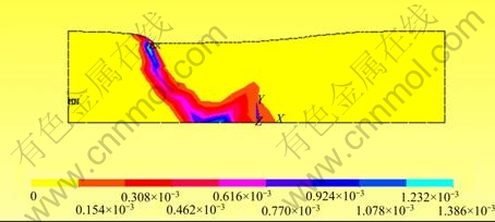
Fig. 11 Shear zone under rigid beam foundation
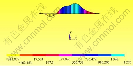
Fig. 12 Bending moment of rigid beam (Unit: kN��m)
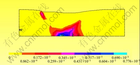
Fig. 13 Shear zone under a flexible beam foundation

Fig. 14 Bending moment of flexible beam (Unit: kN��m)
Therefore, by means of adjusting the longitudinal and vertical section design parameters of beam foundation, the performance of beam-subgrade system was varied significantly, and the impact of crane load on the soft ground was reduced effectively. Since the project was put into operation, track beam foundation showed sufficient bearing capacity, and the effectiveness of the alternative design was confirmed.
4 Conclusions
1) The finite element method has been used successfully to predict the beam foundation bearing capacity and settlement. The calculation results agree well with the measured results in the field. The reliability and feasibility of design parameters optimization of beam foundation on soft soil layers are confirmed.
2) The bearing capacity is influenced by beam width and cushion thickness, and the stresses in subgrade soil decrease greatly with increasing the cushion thickness and width of foundation. However, for a relatively thinner cushion thickness, the foundation settlement and influencing depth of displacement also increase correspondingly. For the foundations on underlying soft laminated clay, increasing foundation width merely might be inadequate for improving the bearing capacity. The appropriate width of foundation depends on the response of the subgrade soil. According to the calculation results, beam width of 2.4 m and cushion thickness of 0.8 m are proposed.
3) Compared with a rigid beam, the influence on subgrade of a flexible track beam is relatively smaller under the same loading conditions, and the flexible beam appears more adaptable to various subgrades, especially for the foundations on weak soil layers. A flexible beam foundation is applied in the optimized design, which is confirmed to be reasonable by the actual engineering.
References
[1] KUMAR J, KHATRI V N. Effect of footing width on bearing capacity factor N? for smooth strip footings [J]. Journal of Geotechnical and Geoenvironmental Engineering, 2008, 134(9): 1299-1310.
[2] HIRD C C, PYRAH I C, RUSSELL D. Finite element analysis of the collapse of reinforced embankments on soft ground [J]. Geotechnique, 1990, 40(3): 633-640.
[3] GRIFFITHS D V. Computation of bearing capacity factors using finite elements [J]. Geotechnique, 1982, 32(3): 195-202.
[4] YANG X L, YIN J H. Slope stability analysis with nonlinear failure criterion [J]. Journal of Engineering Mechanics, 2004, 130(3): 267-273.
[5] YANG X L. Upper bound limit analysis of active earth pressure with different fracture surface and nonlinear yield criterion [J]. Theoretical and Applied Fracture Mechanics, 2007, 47(1): 46-56.
[6] KUMAR J, KOUZER K M. Effect of footing roughness on bearing capacity factor N? [J]. Journal of Geotechnical and Geoenvironmental Engineering, 2007, 133(5): 502-511.
[7] GRIFFITHS D V, GORDON A F. Bearing capacity of rough rigid strip footing on cohesive soil: probabilistic study [J]. Journal of Geotechnical and Geoenvironmental Engineering, 2002, 128(9): 743-755.
[8] KUMAR J. Effect of footing-soil interface friction on bearing capacity factor N? [J]. Geotechnique, 2004, 54(10): 677-680.
[9] LONG Y Q. Calculation Method in Elastic Beam Foundation [M]. Beijing: The People��s Education Press, 1981: 103-148. (in Chinese)
[10] SOUBRA A H. Upper-bound solutions for bearing capacity of foundation [J]. Journal of Geotechnical and Geoenvironmental Engineering, 1999, 125(1): 59-68.
[11] YANG X L, YIN J H. Estimation of seismic passive earth pressures with nonlinear failure criterion [J]. Engineering Structures, 2006, 28(3): 342-348.
[12] UKRITCHON B, WHITTLE A J. Calculation of bearing capacity factor N? using numerical limit analysis [J]. Journal of Geotechnical and Geoenvironmental Engineering, 2003, 129(6): 468-474.
[13] YU Z H, HAN L A. Finite element analysis of alleviating bridge approach settlement with geonet [J]. Chinese Journal of geotechnical engineering, 1996, 16(6): 24-30. (in Chinese)
[14] YU Z H, ZHANG Q S. Finite element analysis for interaction mechanism between soil and geonet [J]. Chinese Journal of Geotechnical Engineering, 1997, 19(3):76-82. (in Chinese)
[15] WEI H W, YU Z H, ZOU Y S. Performances of shear zones and failure modes in Geosynthetic reinforced slopes [J]. Engineering Mechanics, 2006, 23(4): 104-108. (in Chinese)
[16] YANG X L. Seismic bearing capacity of a strip footing on rock slopes [J]. Canadian Geotechnical Journal, 2009, 46(8): 943-954.
[17] YANG X L, YIN J H. Upper bound solution for ultimate bearing capacity with a modified Hoek-Brown failure criterion [J]. International Journal of Rock Mechanics and Mining Sciences, 2005, 42(4): 550-560.
[18] BURD H J, FRYDMAN S. Bearing capacity of plane-strain footings on layered soils [J]. Canadian Geotechnical Journal 1997, 34(2): 241-253.
[19] SARAMA S K, IOSSIFELIS I S. Seismic bearing capacity factors of shallow strip footings [J]. Geotechnique, 1990, 40(2): 265-273.
[20] YANG X L, HUANG F. Collapse mechanism of shallow tunnel based on nonlinear Hoek-Brown failure criterion [J]. Tunneling and Underground Space Technology, 2011, 26(6): 686-691.
[21] YANG X L. Seismic passive pressures of earth structures by nonlinear optimization [J]. Archive of Applied Mechanics, 2011, 81(9): 1195-1202.
[22] YANG X L, WANG J M. Ground movement prediction for tunnels using simplified procedure [J]. Tunneling and Underground Space Technology, 2011, 26(3): 462-471.
(Edited by DENG L��-xiang)
Foundation item: Projects(50778181, 51178472) supported by the National Natural Science Foundation of China; Project(2007045) supported by the Transportation Department of Hunan Province, China
Received date: 2011-03-18; Accepted date: 2011-07-13
Corresponding author: YU Ze-Hong, Professor; Tel: +86-13807319849; E-mail: yzh.edu@163.com
Abstract: Finite element method was performed to investigate the influences of beam stiffness, foundation width and cushion thickness on the bearing capacity of beam foundation on underlying weak laminated clay. The comparison between numerical results and results from field test including plate-bearing test and foundation settlement observation shows reasonable agreement. According to the numerical results, the beam width, length, cross section and cushion thickness were optimized. The results show that the stresses in subgrade soil decrease greatly with increasing the cushion thickness and width of foundation. However, the foundation settlement and influencing depth of displacement also increase correspondingly under conditions of relatively thinner cushion thickness. For the foundations on underlying weak layer, increasing foundation width merely might be inadequate for improving the bearing capacity, and the appropriate width and cushion thickness depend on the response of subgrade. A comparison between rigid and flexible beams was also discussed. The influence of a flexible beam foundation on subgrade is relatively smaller under the same loading conditions, and the flexible beam foundation appears more adaptable to various subgrades. The proposed flexible beam foundation was adopted in engineering. According to the calculation results, beam width of 2.4 m and cushion thickness of 0.8 m are proposed, and a flexible beam foundation is applied in the optimized design, which is confirmed reasonable by the actual engineering.
