
Trans. Nonferrous Met. Soc. China 24(2014) 292-301
Design and fabrication of sintered wick for miniature cylindrical heat pipe
Le-lun JIANG1, Yong TANG2, Wei ZHOU1, Lin-zhen JIANG3, Tan XIAO1, Yan LI1, Jin-wu GAO1
1. School of Engineering, Sun Yat-sen University, Guangzhou 510006, China;
2. School of Mechanical and Automotive Engineering, South China University of Technology, Guangzhou 510640, China;
3. School of Foreign Studies, Yiwu Industrial and Commercial College, Yiwu 322000, China
Received 3 December 2012; accepted 9 June 2013
Abstract:
Miniature cylindrical metal powder sintered wick heat pipe (sintered heat pipe) is an ideal component with super-high thermal efficiency for high heat flux electronics cooling. The sintering process for sintered wick is important for its quality. The sintering process was optimally designed based on the equation of the heat transfer limit of sintered heat pipe. Four-step sintering process was proposed to fabricate sintered wick. The sintering parameters including sintering temperature, sintering time, sintering atmosphere and sintering position were discussed. The experimental results showed that the proper sintering temperature was 950 ��C for Cu powder of 159 ��m and 900 ��C for Cu powders of 81 and 38 ��m, respectively, while the wick thickness was 0.45 mm and sintering time was 3 h. The optimized sintering time was 3 h for 0.45 and 0.6 mm wick thickness and 1 h for 0.75 mm wick thickness, respectively, when copper powder diameter was 159 ��m and sintering temperature was 950 ��C. Redox reduction reaction between H2 and CuO during sintering could produce segmentation cracks in Cu powders as a second structure. Sintering at vertical position can effectively avoid the generation of gap between wick and the inner wall of pipe.
Key words:
heat pipe; wick; sintering; porosity; shrinkage;
1 Introduction
Heat pipe has been widely used in applications ranging from cooling high heat flux electronics to temperature regulation in satellites due to its high heat conductivity, high reliability, fast thermal response, and no extra electric power [1]. As a heat transfer component based on phase change, heat pipe essentially consists of 3 parts: sealed container, working fluid and wick. The wick structure provides the necessary capillary driving force to maintain a closed circulation of working fluid and thus facilitate heat transfer. The property of wick structure is mainly characterized by porosity, effective pore radius and permeability. To maximize the function of cylindrical heat pipe, the wick structure is expected to be with high permeability and high capillary pumping force. Sintered heat pipe has relatively high capillary pumping ability and good anti-gravity ability, compared to grooved wick heat pipe and screen wick heat pipe [2]. The fabrication process of sintered wick in miniature heat pipe for electronics cooling is worth studying.
Current research on sintered wick heat pipe is mainly focused on its heat transfer mechanism and thermal performance [3-14], but less on fabrication process of sintered wick for heat pipe. Solid-state sintered method is always adapted to fabricate sintered wick for flat plate heat pipe, loop heat pipe, micro heat pipe, and grooved-sintered heat pipe. LEONG et al [15] fabricated rectangular sintered wicks with copper powders (63 ��m) for flat plate heat pipes at sintering temperatures of 800 and 1000 ��C. The size of most pores was obtained in the range of 30-40 ��m. CHIU et al [16] fabricated oxide-reduced and water-atomized copper powder sintered wicks at temperatures of 800-1000 ��C in a reduction stream of 10% hydrogen and 90% argon. The results showed that 900 ��C was a recommended sintering temperature for producing wicks with lower volume shrinkage and higher permeability. XIN et al [17] fabricated capillary wicks for loop heat pipes by cold-pressing sintering method and direct loose sintering method. It was found that the optimal capillary wick with 90% nickel and 10% copper was obtained by sintering at 650 ��C for 30 min with direct and loose sintering technique. LI et al [18,19] investigated the fabrication process of the sintered wick in the micro heat pipe. Results showed that the sintered wick with copper powders of 140-170 ��m at sintering temperature of 900-950 ��C and sintering time of 30-60 min had low manufacturing cost and high thermal performance. JIANG et al [20] fabricated grooved-sintered wick in the heat pipe. Results demonstrated that grooved-sintered wick with 150 ��m spherical copper powders had high porosity and low radial shrinkage at the sintering temperature of 950 ��C for 3 h. According to above discussion, the solid-state sintered process parameters for sintered wick were in confusion and the wick sintering process for miniature sintered cylindrical heat pipe was rare and worth investigating.
The main goal of this research was to design and fabricate copper powder sintered wick for miniature cylindrical heat pipe with high thermal performance. To achieve this goal, firstly, sintered wick was characterized and thermal performance was calculated to optimize structure parameters and its sintering process; secondly, four-step sintering process for sintered wick was proposed to fabricate the experimental samples; finally, appropriate sintering parameters to fabricate sintered heat pipe of high thermal performance and low cost would be discussed.
2 Theory analysis
2.1 Characterization of sintered wick
The sintered wick of heat pipe is fabricated by single-component system loose solid-state sintering method. The sintering principle for sintered wick of miniature cylindrical heat pipe is shown in Fig. 1. A pipe with one shrunk end is used as the outside wall, a stainless steel bar is insert into the pipe as the inner mandrel. Powders are then filled into the gap between wall and mandrel. The pipes with full filled powders are placed vertically in the furnace and sintered at appropriate temperature. Finally, the powders are sintered together as the sintered wick on inner pipe wall.
During the sintering process, the atoms migrate between the contact powders and metal powders are then fused, the sintering necks are formed, and the bonding strength of sintered wick is improved. The effective thermal conductivity and volume shrinkage of sintered wick increase, while the porosity of sintered wick decreases. In order to better analyze sintering process of sintered heat pipe, the parameters like sintering neck, shrinkage and porosity should be firstly characterized.
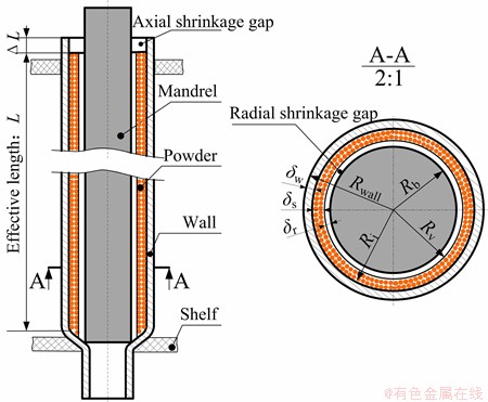
Fig. 1 Sintering principle of sintered wick
2.1.1 Sintering neck growth rate
Sintering neck formation can be analyzed by the ball-ball sintering model [21,22], as shown in Fig. 2. The sintering neck growth equation [23] can be expressed by
 (1)
(1)
where n and m are the sintering mechanism characteristic parameters; Ts is the sintering temperature; F(Ts) is the sintering temperature function; ts is the sintering time; x is the length of sintering neck and rcu is the copper powder radius. Neck growth ratio �� is defined as a neck dimension divided by the powder diameter. According to Eq. (1), the sintering growth rate is a function of sintering time, sintering temperature and sintering powder radius. The experimental powder radius rCu always fluctuates in a considerable range and can be calculated by the mean value of two bonded powders radius. Thus, the sintering growth rate can be expressed as
 (2)
(2)
where rave is the average radius of copper powders.
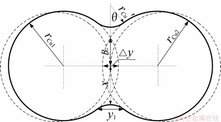
Fig. 2 Ball-ball sintering model
2.1.2 Shrinkage
Wick shrinkage greatly reduces wick porosity which affects the thermal performance of sintered heat pipe. According to shrinkage direction, the wick shrinkage can be classified into axial shrinkage and radial shrinkage. The axial wick shrinkage gap can be observed at the upper end of pipe and can be defined as
 (3)
(3)
where la is the axial shrinkage rate of sintered wick; DL and L are the axial shrinkage length and total length of sintered wick, respectively.
The powders are easily sintered on the inner surface of pipe wall and difficultly bonded on the mandrel. Therefore, the radial shrinkage gap always occurs between mandrel and sintered wick. The radial shrinkage rate lr can be defined as
 (4)
(4)
where dr and ds are the shrinkage gap thickness and sintered wick thickness, respectively.
2.1.3 Porosity
The porosity of sintered wick has a profound influence on the maximum heat transfer rate according to the working principle of heat pipe [3]. A lot of measuring methods, such as Archimedes method based on imbibition��s principle [17], density method [11,23,24], and soaking method [24], can be used to test the porosity of sintered wick. In the present work, density method is conducted to calculate porosity of sintered wick e due to its simplicity and effectiveness as follows:
 (5)
(5)
where ��Cu is the density of pure copper which is equal to 8993 kg/m3; ��w is the density of sintered wick; mw is the mass of sintered wick; Vw is the total volume of sintered wick.
The mass lose during the sintering process is minimal and ignored. The relationship between porosity and shrinkage rate of sintered wick can be expressed as
 (6)
(6)
where Ri is the radius of inner wall; Rb is the radius of mandrel; and e0 is the porosity of filled powder before sintering.
2.2 Heat transfer limit of sintered heat pipe
The heat transfer capability of heat pipe may be determined by several limits, such as capillary limit, boiling limit, entrainment limit, sonic limit, viscous limit [25]. For copper-water cylindrical heat pipes generally operating from 30 to 100 ��C, the boiling limit and capillary limit govern the thermal performance of heat pipe [26]. Therefore, the heat transfer limit of sintered heat pipe is determined by the minimum value of boiling limit Qb,max and capillary limit Qcap,max. Thus, the maximum heat transfer capability of sintered heat pipe Qmax can be given as follows:
 (7)
(7)
2.2.1 Capillary limit
Wick structure provides necessary flow path and capillary pumping force to return the liquid from the condenser to the evaporator. For a given wick structure, it has a maximum value of capillary pumping force. If the sum of pressure drop along the fluid circulation in the sintered heat pipe is larger than the maximum value of capillary pumping force, the liquid-vapor interface would recede to reach a new pressure balance. If the new balance cannot be reached, heat pipe would be dry out due to no sufficient liquid returning to evaporate. So the sintered heat pipe should have enough capillary pumping force to maintain the continuity of interfacial evaporation. CHI [25] proposed that the maximum capillary limit can be calculated as the sintered heat pipe works along the horizontal direction by the following equation:
 (8)
(8)
where ��l is the liquid density of working fluid; ��l is the surface tension of working fluid; hfg is the fluid latent heat of vaporization; g is the gravitational acceleration; ��l is the liquid viscosity; Aw is the cross area of sintered wick; rh is the effective pore radius of wick; Leff is the effective length of heat pipe; and K is the wick permeability.
2.2.2 Boiling limit
Heat transfer mechanism at the evaporator is heat conduction and evaporation. When the heat flux is sufficiently high, the liquid in the porous wick would be superheat and nucleate boiling may occur. The bubbles which are formed by nucleate boiling may be trapped in porous wick. The pressure of the bubbles would obstruct the working liquid circulation which causes hot spots on heated wall. The heat flux at which marks the onset of nucleation is defined as the boiling limit of sintered heat pipe. The boiling limit model can be expressed as follows [26]:
 (9)
(9)
where Le is the length of evaporator section; keff is the effective thermal conductivity of sintered wick; Tv is the vapor temperature; ��v is the density of vapor; Ri is the outer radius of sintered wick which is equal to the inner radius of wall; Rv is the vapor chamber radius of heat pipe. CHI [25] conservatively suggested the critical radius of the bubbles rb to be a value on the order of 25.4-254 nm for the copper water heat pipes. The theory of LORENZ et al [27] predicted that the first active nucleation sites were larger, so the bubble radius rb was taken the value 254 nm in this study.
2.3 Optimization design of sintered wick
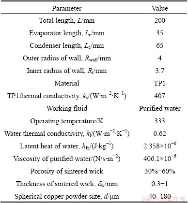
In order to optimize the design of sintered wick structure, heat pipe is assumed to work at the vapor temperature of about 60 ��C based on its general operating temperature applied in electronics cooling. The experimental and calculation parameters of sintered wick heat pipe are shown in Table 1. According to the calculation results of Eqs. (8) and (9), the heat transfer limit of the copper water sintered heat pipe is determined by the capillary limit.
Table 1 Experimental and calculation parameters of sintered heat pipe
The effects of powder diameter, porosity and sintered wick thickness on heat transfer limit of heat pipe are vividly shown in Fig. 3. Heat transfer limit of heat pipe increases with sintered wick thickness in the range from 0.3 to 1 mm at a given porosity and powder diameter. However, fabrication cost, mass and thermal resistance of sintered heat pipe would also increase due to the increase of sintered wick thickness. Therefore, an optimum sintered wick thickness design should be as thin as possible under the condition of meeting the heat transfer capacity.
As shown in Fig. 3, heat transfer limit of heat pipe also increases with porosity of sintered wick and powder diameter. The porosity of sintered wick is determined by the original porosity of filled copper powder ��0, the radial shrinkage rate ��r and the axial shrinkage rate ��a after sintering. In a word, heat transfer limit of heat pipe is affected by powder diameter and shrinkage. Radial shrinkage rate increases with the sintering process which leads to the decrease of wick porosity. However, radial wick shrinkage should guarantee that the mandrel can be pulled out from sintered wick. The diameter of mandrel is assumed as a constant, the fitness relationship of mandrel and sintered wick should belong to clearance fit of basic shaft system. Therefore, there is an optimal point of the sintering process that ensures relatively high porosity and proper radial shrinkage of sintered wick.
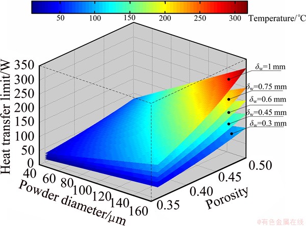
Fig. 3 Effects of powder diameter, porosity and wick thickness on heat transfer limit
3 Experimental
3.1 Preparation
100 mesh, 200 mesh and 300 mesh spherical copper powders (Material: TP1, supplied by a Cu powder International, LLC, USA) made by gas atomization were screened as raw materials for sintered wick. The influence of powder diameter distribution on porosity of sintered wick should be considered. 100 mesh, 200 mesh and 300 copper powders were observed by SEM. Powder diameter was analyzed and powder diameter distribution was calculated by statistical method. The normal distributions of different size of powder diameter are vividly shown in Fig. 4. The mean diameters of 100 mesh, 200 mesh and 300 mesh copper powders are 159 mm, 81 mm and 38 mm respectively.
The material of pipe wall was also copper (Material: TP1) due to its high thermal conductivity. Its geometric parameters are shown in Table 1. The material of mandrel was stainless steel (Material: 310S) due to its high temperature resistance, high mechanical strength and non-sticking with copper powder at high temperature.

Fig. 4 Normal distribution of spherical copper powder
The diameter of mandrel mainly determines the sintered wick thickness at a given wall. Diameters of 6.8, 6.5, 6.2 and 5.9 mm and length of 250 mm stainless steel bars were fabricated as the mandrels.
Before the beginning of sintering process, a series of preparation processes as follows had to be done: 1) cut pipes with the length of 250 mm; 2) shrink one end of pipe to d5 mm with the length of 50 mm by the radial forging and swaging method; 3) clean pipe and stainless steel mandrel by ultrasonic cleaning machine; 4) fix mandrel in center of the pipe and fill copper powder into the gap between pipe and mandrel; 5) vertically place the filled pipe into graphite shelf and move the shelf in a sintering furnace (Model: ZKL1600, Shanghai Jiugong Electrical Apparatus Co., Ltd, China).
3.2 Sintering process
A sintering process for sintered wick of heat pipe was proposed based on the powder sintering theory shown in Fig. 5. The sintering process was carried out in the sintering furnace under gas protection atmosphere. The sintering process can be divided into 4 stages: reduction step, starting step, preservation step and cooling step.
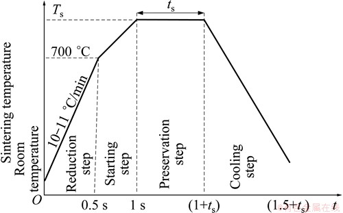
Fig. 5 Sintering process for sintered wick
In reduction step, the pipes filled with copper powders placed in the furnace began to be sintered. Firstly, seal and pump the furnace at the vacuum degree of 0.1-1 Pa. Secondly, blow 90% protecting gas N2 and 10% reducing gas H2 into the furnace till the pressure of atmosphere reached about 0.3 MPa. When the furnace temperature was about 350 ��C, exhaust the atmosphere and pump in 100% protecting gas N2. The temperature increase rate was set at 1000 ��C/h till the furnace temperature reached 700 ��C. During the reduction process, the oxide layer of copper powders and pipe was reduced into steam. Steam and impurity gases released from organic compounds were exhausted. The reduction process guaranteed the golden yellow surface quality of sintered wick.
In starting step, thermal inertia of furnace increased with heating rate which could lead to furnace temperature far over the sintering temperature. Thus, the furnace heating rate decreased from 1000 to 500 ��C/h when the furnace temperature reached 700 ��C. When the furnace temperature was beyond 700 ��C, the copper powder began to stick together, the sintering neck formed, the strength of the sintered wick increased, but the morphology of the sintered wick almost remained unchanged.
In preservation step, the furnace was heated at a fixed temperature for a holding time. The holding temperature and holding time were defined as the sintering temperature and sintering time, respectively. During the preservation phase, the sintered necks grew, the center distance of adjacent powders decreased, and the shrinkage rate, the effective capillary pore radius and the bonding strength of sintered wick increased. Thus, it is the key step of sintering process which decides property of sintered wick.
In cooling step, the furnace temperature was cooled by its internal recycling N2 gas at the cooling rate of 600 ��C/h. The hardness of sintered pipe was affected by the cooling rate and the tapping temperature of sintered pipe. If the tapping temperature was high, the sintered pipe may be oxidized. The appropriate tapping temperature was about 120 ��C.
3.3 Samples testing
The sintered samples including sintered pipe and mandrel were cut by wire cutting method at the cross section. Cross section was observed by SEM and the radial shrinkage was calculated by Eq. (4) based on SEM images. In axial direction, the shrinkage length of wick was measured by a caliper, and the axial shrinkage rate was calculated by Eq. (3). The original powder porosity before sintering can be calculated by density method in Eq. (5). Finally, the porosity of sintered wick can be calculated by Eq. (6) based on calculated original powder porosity and shrinkage rate.
4 Results and discussion
4.1 Sintering temperature
Higher sintering temperature means faster mass transfer velocity, which leads to the enhancement of sintering neck growth rate and shrinkage rate of sintered wick. Figure 6 shows the effects of sintering temperature on sintering neck of 81 ��m copper powders at the sintering time of 3 h. The mean sintering neck growth rates are about 22.7%, 30.8% and 35.6% when the sintering temperatures are 850, 900 and 950 ��C, respectively. The sintering neck growth rate increases with sintering temperature.
As the sintering neck grows, the shrinkage rate also increases. Figure 7(a) shows the effect of sintering temperature and copper powder diameter on porosity and radial shrinkage rate of sintered wick with 0.45 mm wick thickness for 3 h of sintering time. The radial shrinkage rate of sintered wick greatly increases with sintering temperature and decreases with copper powder diameter. The proper radial shrinkage gap value for easily pulling mandrel out from sintered wick is beyond 0.015 mm due to its clearance fit of basic shaft system. In other words, the proper radial shrinkage rate should be beyond 3.5% when the wick thickness is about 0.45 mm. Thus, the optimal sintering temperature for 159 ��m copper powder sintered wick is about 950 ��C with the radial shrinkage rate of 3.68%, and 900 ��C for 81 and 38 ��m copper powder sintered wick. The axial shrinkage of sintered wick in the sintered pipe varies due to the effects of powders gravity and frictions along the axial pipe wall. The mean axial shrinkage rates of 159, 81 and 38 ��m copper powder sintered wick are about 1.13%, 1.15% and 1.19%, respectively, when sintering temperature is 950 ��C and sintering time is 3 h. The axial shrinkage rate is relatively small and its effect on porosity can be neglected.
The porosity of sintered wick decreases with the sintering temperature for 3 h sintering time, as shown in Fig. 7(b). The porosities of 159 ��m copper powder sintered wick are about 49.5%, 48.9% and 47.7% at the sintering temperatures of 900, 950 and 1000 ��C, respectively. The wick porosity almost decreases about 5% by comparing porosity at sintering temperature of 1000 ��C to original powder porosity of 50.1% before sintering. It is due to the increase of axial and radial shrinkage at a given original porosity of filled copper powder according to Eq. (6). The wick porosity increases with spherical copper powder diameter, as shown in Fig. 7(b), due to the increase of original porosity of filled copper powder.
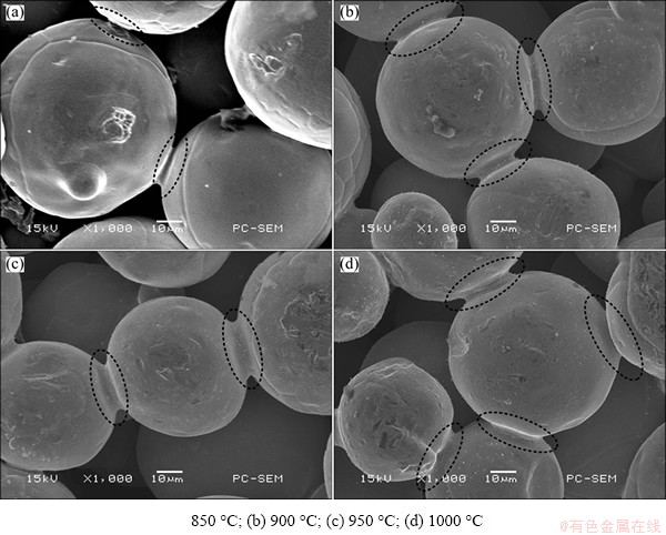
Fig. 6 Effects of sintering temperature on sintering neck: 850 ��C
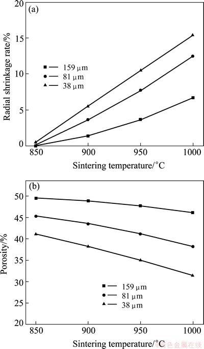
Fig. 7 Radial shrinkage rate (a) and porosity (b) at different sintering temperature
The positive slope of radial shrinkage rate increases with copper powder diameter while the negative slope of porosity is reversed, as shown in Fig. 7. This is reasonable that the small-size copper powders have relatively large specific surface area and higher free energy compared with larger size copper powders. Therefore, the copper powders of small size are easier to be sintered together and produce larger sintered neck growth rate.
According to above discussion, with 3 h sintering time, the optimal sintering temperature is 950 ��C for 159 ��m sintered wick with the porosity 47.7% and 900 ��C for 81 and 38 ��m of 0.45 mm thickness sintered wick.
4.2 Sintering time
Figure 8(a) shows effect of sintering time and wick thickness on radial shrinkage rate of 159 ��m sintered wick at 950 ��C sintering temperature. The radial shrinkage rate of sintered wick increases with sintering time. The mass transfer among the copper powders leads to the growth of sintering neck and wick shrinkage as the sintering proceeds. According to previous discussion, the proper radial shrinkage rate value for easily pulling mandrel out from sintered wick is its clearance fit of basic shaft system between wick and inner wall. Thus, the proper sintering time is about 3 h for 0.45 and 0.6 mm thickness sintered wick and 1 h for 0.75 mm according to their radial shrinkage rates. However, the mandrel is difficult to be pulled out even 5 h sintering time for 0.3 mm thickness sintered wick due to friction between sintered wick and mandrel. The axial shrinkage rate increases with wick thickness due to powder gravity and friction. The value is relatively small, varing from 0.95% to 1.7%.

Fig. 8 Radial shrinkage rate (a) and porosity (b) at different sintering time
Figure 8(b) shows the effect of sintering time and wick thickness on wick porosity with 159 ��m copper powder diameter at 950 ��C sintering temperature. The wick porosity slightly decreases with the wick thickness due to axial shrinkage. The wick porosity also slightly decreases with the sintering time. The effect of sintering temperature on sintering process is greater than sintering time compared with the decrease of wick porosity in Fig. 7(b) and Fig. 8 (b). Therefore, a low cost and high efficiency sintering process to fabricate sintered wick with reasonable radial shrinkage and high porosity is to enhance sintering temperature and reduce sintering time. The proper sintering process for 159 ��m powder and 0.45 mm or 0.6 mm wick thickness is 950 ��C sintering temperature and 3 h sintering time, and for 0.75 mm wick thickness is 950 ��C sintering temperature and 1 h sintering time.
4.3 Sintering atmosphere
Figure 9 shows the surface morphology of spherical copper powders before and after sintering process. The copper powder surface distributes plenty of micro cracks before sintering, as shown in Fig. 9(a). After sintering process, the copper powder has a very smooth surface, as shown in Fig. 9(b). The surface of copper powder is melt and micro cracks are filled due to mass transfer during the sintering process. Finally, the reduced sintered wick and pipe have a smooth and golden surface.
Figure 9(c) shows plenty of segmentation cracks in the copper powder surface after sintering. This phenomenon can be explained as follows. The copper powders are intensively oxidized at grain boundaries by oxygen in the air before sintering. The oxidized copper reacts with hydrogen in the sintering atmosphere during the sintering process and generates water vapor. The water vapor cannot escape to the ambient and be trapped inside the powder. The water vapor expands as the sintering proceeds, resulting in cracking in the powder surface. The segmentation cracks as the second structure can enhance the specific surface area of sintered wick and also increase thermal performance of heat pipe [28].
4.4 Sintering position
Figure 10 shows SEM images of sintered wick which is respectively sintered at horizontal and vertical sintering position. LI et al [19] proposed to sinter copper powder wick at horizontal position. However, a gap was found between wall and sintered wick during sintering, as shown in Fig. 10(a). Gravity would pull top section of sintered wick from wall and form a gap. The gap greatly increases the thermal resistance between wall and sintered wick. The gravity also pulls top section of sintered wick close to the mandrel resulting in difficulty of drawing the mandrel out.

Fig. 9 Surface morphology of copper powder
Wick, as shown in Fig. 10(b), is sintered at vertical sintering position and can solve above problem. The forces of gravity and friction can reach balance and the copper powders cannot easily flow along axial direction to the bottom of sintered pipe. The porosity along axial direction is relatively uniform.
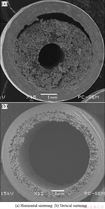
Fig. 10 SEM images of sintered wick at different sintering position
5 Conclusions
1) Sintered wick structure is optimized based on thermal performance of miniature cylindrical heat pipe. Heat transfer limit increases with porosity thickness and powder diameter of sintered wick. An optimal sintering process should keep balance between high porosity and proper radial shrinkage for mandrel pulling out.
2) Sintering temperature is the key sintering process parameter that greatly affects sintering neck growth, porosity and shrinkage. Sintering neck growth rate and radial shrinkage increase with sintering temperature while porosity reverses. The proper sintering temperature is 950 ��C for 159 ��m sintered wick, and 900 ��C for 81 and 38 ��m when the wick thickness is 0.45 mm and sintering time is 3 h.
3) Sintering time also affects porosity and shrinkage. Radial shrinkage increases with sintering time, and porosity decreases with sintering time. The proper sintering time is 3 h for 0.45 and 0.6 mm wick thickness, and 1 h for 0.75 mm wick thickness when copper powder diameter is 159 ��m and sintering temperature is 950 ��C.
4) Sintering atmosphere guarantees smooth and golden surface of sintered pipe. Segmentation cracks may form during sintering due to reaction between the intrinsic oxygen in the copper powders and the hydrogen in the atmosphere. To sinter copper powder wick at vertical position can avoid the generation of gap between wick and the inner wall of pipe.
References
[1] McGLEN R J, JACHUCK R, LIN S. Integrated thermal management techniques for high power electronic devices [J]. Applied Thermal Engineering, 2004, 24(8-9): 1143-1156.
[2] HUANG X, FRANCHI G. Design and fabrication of hybrid bi-modal wick structure for heat pipe application [J]. Journal of Porous Materials, 2008, 15 (6): 635-642.
[3] CHEN Y M, WU S C, CHU C I. Thermal performance of sintered miniature heat pipes [J]. Heat and Mass Transfer, 2001, 37(6): 611-616.
[4] TSAI Y S, CHANG Y M, CHAN J H, WU S C, CHEN Y M. Enhancement of thermal performance in a sintered miniature heat pipe [J]. Journal of the Chinese Institute of Engineers, 2005, 28(2): 359-363.
[5] GARIMELLA S V, IVERSON B D, DAVIS T W, NORTH M T, KANG S S. Heat and mass transport in heat pipe wick structures [J]. Journal of Thermophysics and Heat Transfer, 2007, 21(2): 392-404.
[6] GARIMELLA S V, WEIBEL J A, NORTH M T. Characterization of evaporation and boiling from sintered powder wicks fed by capillary action [J]. International Journal of Heat and Mass Transfer, 2010, 53(19-20): 4204-4215.
[7] CHING C Y, RUSSEL M K, YOUNG C, COTTON J S. The effect of orientation on U-shaped grooved and sintered wick heat pipes [J]. Applied Thermal Engineering, 2011, 31(1): 69-76.
[8] PRUZAN D A, KLINGENSMITH L K, TORRANCE K E, AVEDISIAN C T. Design of high-performance sintered-wick heat pipes [J]. International Journal of Heat and Mass Transfer, 1991, 34(6): 1417-1427.
[9] MAZIUK V, KULAKOV A, RABETSKY M, VASILIEV L, VUKOVIC M. Miniature heat-pipe thermal performance prediction tool-software development [J]. Applied Thermal Engineering, 2001, 21(5): 559-571.
[10] HANLON M A, MA H B. Evaporation heat transfer in sintered porous media [J]. Transactions-American Society of Mechanical Engineers. Journal of Heat Transfer, 2003, 125(4): 644-652.
[11] AHMED Y M Z, RIAD M I, ZAKY A I, ABDEL-AZIZ M, SHALABI M M H. Investigation on the mechanical properties of sintered porous copper compacts [J]. China Particuology, 2007, 5(6): 391-394.
[12] LIN Y J, HWANG K S. Effects of particle size and particle size distribution on heat dissipation of heat pipes with sintered porous wicks [J]. Metallurgical and Materials Transactions A��Physical Metallurgy and Materials Science A, 2009, 40(9): 2071-2078.
[13] RUSSEL M K, YOUNG C, COTTON J S, CHING C Y. The effect of orientation on U-shaped grooved and sintered wick heat pipes [J]. Applied Thermal Engineering, 2011, 31(1): 69-76.
[14] SAKULCHANGSATJATAI P, THUCHAYAPONG N, TERDTOON P, SANGSIRAKOUP N. Effect of tube bending on heat transfer characteristics of miniature heat pipe with sintered porous media [J]. Defect and Diffusion Forum 2011, 1265(312): 1015-1020.
[15] LEONG K C, LIU C Y, LU G Q. Characterization of sintered copper wicks used in heat pipes [J]. Journal of Porous Materials, 1997, 4(4): 303-308.
[16] CHIU L H, WU C H, LEE P Y. Comparison between oxide-reduced and water-atomized copper powders used in making sintered wicks of heat pipe [J]. China Particuology, 2007, 5(3): 220-224.
[17] XIN G M, CUI K H, ZOU Y, CHENG L. Development of sintered Ni-Cu wicks for loop heat pipes [J]. Science in China Series E: Technological Sciences, 2009, 52(6): 1607-1612.
[18] LI X B, LI Y, TANG Y, ZHOU S Z. Forming method of sintered wick in micro heat pipe [J]. Journal of South China University of Technology, 2008, 36(10): 114-119.
[19] LI X B, TANG Y, LI Y, ZHOU S Z, ZENG Z X. Sintering technology for micro heat pipe with sintered wick [J]. Journal of Central South University of Technology, 2010, 17(1): 102-109.
[20] JIANG L L, TANG Y, PAN M Q, C LI C. Fabrication of sintered wick in mirco-grooved pipe[C]//2010 International Conference on Mechanic Automation and Control Engineering. Wuhan: 2010: 5868-5871.
[21] DEMIRSKYI D, AGRAWAL D, RAGULYA A. Neck growth kinetics during microwave sintering of copper [J]. Scripta Materialia, 2010, 62(8): 552-555.
[22] DEMIRSKYI D, AGRAWAL D, RAGULYA A. Neck growth kinetics during microwave sintering of nickel powder [J]. Journal of Alloys and Compounds, 2011, 509(5): 1790-1795.
[23] SEMENIC T, LIN Y Y, CATTON I. Thermophysical properties of biporous heat pipe evaporators [J]. Journal of Heat Transfer-Transactions of the ASME, 2008, 130(2): 22602.
[24] SINGH R, AKBARZADEH A, MOCHIZUKI M. Effect of wick characteristics on the thermal performance of the miniature loop heat pipe [J]. Journal of Heat Transfer-Transactions of the Asme, 2009, 131(1): 082601.
[25] CHI S W. Heat pipe theory and practice [M]. Washington, D.C.: Hemisphere Publishing Corporation, 1976.
[26] WILLIAMS R R, HARRIS D K. The heat transfer limit of step-graded metal felt heat pipe wicks [J]. International Journal of Heat and Mass Transfer, 2005, 48(2): 293-305.
[27] LORENZ J J, MIKIC B B, ROBSENOW W M. Effect of surface conditions on boiling characteristics [C]//International Heat Transfer Conference. Tokyo: Avgonne National Lab, 2012.
[28] VITYAZ P A, KONEV S K, MEDVEDEV V B, SHELEG K V. Heat pipes with bidispersed capillary structures [C]//Proceedings of 5th International Heat Pipe Conference. Tsukuba, 1984: 127-135.
С��Բ�ȹ��ս���Һо�����������
������1���� ��2���� ΰ1��������3��Ф ̶1���� ��1���߽���1
1. ��ɽ��ѧ ��ѧԺ������ 510006��
2. ����������ѧ ��е������ѧԺ������ 510640��
3. ���ڹ���ѧԺ �����ѧԺ������ 322000
ժ Ҫ��С�ͽ�����ĩ�ս���ҺоԲ�ȹ�(����ս��ȹ�)��һ����߸������ܶȵ���Ԫ����ɢ���Եĸ��ȵ���Ԫ�������սṤ���Ǿ����ս��ȹ������Ĺؼ��������ս��ȹܴ��������Ż��ȹ���Һо�Ľṹ�����գ���������ȹ��ս���Һо���Ľι����սṤ�գ������սṤ�ղ������ս��¶ȡ��ս�ʱ�䡢�ս����պ��ս�λ�á�������������ս���Һо���Ϊ0.45 mm���ս�ʱ��Ϊ3 hʱ��159 ��mͭ�۵��ս���Һо�������ս��¶���950 ��C��81 ��m��38 ��mͭ�۵��ս���Һо�������ս��¶�Ϊ900 ��C����ͭ������Ϊ159 ��m���ս��¶�Ϊ950 ��Cʱ��0.45��0.6 mm��Һо��Ⱥ������ս�ʱ��Ϊ3 h����0.75 mm��Һо��Ⱥ������ս�ʱ��Ϊ1 h�����ս������H2��CuO��ԭ��Ӧ�ܹ���ͭ�۱����γɹ����ƣ��������ƿ���Ϊ���νṹ��ˮƽλ���ս�����Ч�ر����ս���Һо��ͭ���ڱ�֮�������϶��
�ؼ��ʣ��ȹܣ���Һо�������ս��϶�ʣ�����
(Edited by Chao WANG)
Foundation item: Project (50905119) supported by the National Natural Science Foundation of China; Project (20120171120036) supported by New Teachers' Fund for Doctor Stations, Ministry of Education, China; Project (S2012040007715) supported by Natural Science Foundation of Guangdong Province��China
Corresponding author: Le-lun JIANG; Tel: +86-20-39332153; E-mail: jianglel@mail.sysu.edu.cn
DOI: 10.1016/S1003-6326(14)63060-0
Abstract: Miniature cylindrical metal powder sintered wick heat pipe (sintered heat pipe) is an ideal component with super-high thermal efficiency for high heat flux electronics cooling. The sintering process for sintered wick is important for its quality. The sintering process was optimally designed based on the equation of the heat transfer limit of sintered heat pipe. Four-step sintering process was proposed to fabricate sintered wick. The sintering parameters including sintering temperature, sintering time, sintering atmosphere and sintering position were discussed. The experimental results showed that the proper sintering temperature was 950 ��C for Cu powder of 159 ��m and 900 ��C for Cu powders of 81 and 38 ��m, respectively, while the wick thickness was 0.45 mm and sintering time was 3 h. The optimized sintering time was 3 h for 0.45 and 0.6 mm wick thickness and 1 h for 0.75 mm wick thickness, respectively, when copper powder diameter was 159 ��m and sintering temperature was 950 ��C. Redox reduction reaction between H2 and CuO during sintering could produce segmentation cracks in Cu powders as a second structure. Sintering at vertical position can effectively avoid the generation of gap between wick and the inner wall of pipe.
