

3D anisotropy simulation of dendrites growth with phase field method
HOU Hua(�� ��)1, ZHAO Yu-hui(�����)2, NIU Xiao-feng(ţ����)1
1. College of Materials Science and Engineering, North University of China, Taiyuan 030051, China;
2. Department of Mechanical and Electronic Engineering, Hebei College of Industry and Technology,
Shijiazhuang 050091, China
Received 12 June 2008; accepted 5 September 2008
Abstract:
The anisotropy problem of 3D phase-field model was studied, and various degrees of anisotropy were simulated by numerical calculation method. The results show that with the change of interface anisotropy coefficients, from smooth transition to the appearance of angle, equilibrium crystals shape morphology has a critical value, and 3D critical value is 0.3. The growth of dendrites is stable and the interface is smooth when it is less than critical value; the interface is unstable, rolling edge appears and the growth is discontinuous when it is more than critical value. With the increase of anisotropy coefficients, the dendrites grow faster under the same condition.
Key words:
anisotropy; dendrite growth; crystal morphology; phase field method;
1 Introduction
The process of metal solidification is affected not only by macroscopic conditions, but also by microcosmic internal characteristics. The most important factor of internal characteristic is the anisotropy phenomenon at the solid/liquid interface, and it is a key parameter affecting the evolution of crystal morphology. As long as free dendrites form stable morphology of tip, it must have anisotropy. At the same time, the growth direction and radius of dendrites tip is related to the anisotropy of interface.
Anisotropy of solid/liquid interface includes interface energy anisotropy and interface dynamics anisotropy[1]. KESSLER and LEVINE[2-5] studied the dendrite solidification process controlled by heat diffusion and concluded that the interface energy anisotropy can not only determine the dendrite tip growth speed by monotone value but also affect the dendrite morphology evolution and growth stability. SAITO et al[6] studied the dendrite growth controlled by the solute diffusion and their results showed that interface energy anisotropy inevitably existed in dendrite growth process. The interface dynamics anisotropy[3-5, 7-8] influences the dendrite interface growth speed. YOUNG et al[9] proposed that the interface dynamics could be related to the interface crystal orientation.
The simulation of the solidification microstructure evolution by phase field model has been a hot field for recent years. In the phase field model[10-15], the effect of anisotropy could be expressed by the angle function between the interfacial normal orientation and the specific orientation. At present, the investigations on phase field model are mainly focused on the plane of weak anisotropy (the coefficient of anisotropy is less than 0.067), and the investigations on the plane of strong anisotropy are very few[16-18]. Until recently, EGGLESTON[19] presented the modification method of strong anisotropy. The phase field model under interface proposed by LO and KARMA[20], ROBERT[21] has important theoretical and practical value, and it can be used to qualitatively simulate growth of dendrites. In this work, the interface energy anisotropy and interface dynamics anisotropy are introduced to describe the dendrite growth precisely. And this could actually describe the evolution of crystal structure and establish the foundation of studying the crystal growth in complex condition.
2 Phase field model
According to Karma��s thin interface theory, phase field model of non-isothermals pure substance is constructed based on the entropy function.
Eqn.(1) is the phase field governing
![]()
![]()
![]() (1)
(1)
where t is non-dimensional time, ![]() ;
; ![]() is non-dimensional length,
is non-dimensional length, ![]() ;
; ![]() is non- dimensional interface thickness,
is non- dimensional interface thickness, ![]() ;
; ![]()
![]() , and m=�̦�TM/(DL) are the non- dimensional dynamics coefficient; W is the parameter related to the interface thickness. W is selected as 2.3��10-8 m, and the mesh dimension are selected as dx=dy=0.4, dt=0.005.
, and m=�̦�TM/(DL) are the non- dimensional dynamics coefficient; W is the parameter related to the interface thickness. W is selected as 2.3��10-8 m, and the mesh dimension are selected as dx=dy=0.4, dt=0.005.
Pure nickel is selected to do the simulation, and the calculation parameters are listed in Table 1.
Table 1 Thermo-physical parameters of pure nickel
3 Effect of interface anisotropy on equilibrium state
In whole description of the simulation of dendrites growth, the anisotropy must be considered, which exists on the solid/liquid interface, as shown in Fig.1.
During the growth of 3D dendrites, the forms of interfacial energy and interfacial dynamics anisotropy in the phase field are as follows.
The interfacial energy anisotropy:
W(n)=W0AS(n) (2)
where W(n) is the interfacial energy.
The interfacial dynamics anisotropy:
��(n)= ��0AS(n)2 (3)
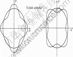
Fig.1 Expression of anisotropy
![]()
![]() (4)
(4)
where ��4 is the coefficient of anisotropy, n is the vector of interface normal, and it is equal to ![]() .
.
Using spherical coordinates, Eqn.(4) can be expressed as
![]() (5)
(5)
Interface anisotropy is usually expressed by using external graphs of AS(n) and 1/AS(n), and AS(n) is only a function of �� in the planar space. The balanceable shapes which conform to the Wuff law correspond to the AS(n) extremal graphs, which have already been analyzed above. In the 3D space, AS(n) is the function of �� and ��, so it is difficult to analyze the lost crystal direction, and Hoffman and Cahn vector �� is used here. The form of vector �� is shown as follows:
![]() �� (6)
�� (6)
Let ��(n)=AS(n), n, ��, �� is the unit vector in the spherical coordinates. To the vector ��, the Gibbs- Thomson equation which considered the anisotropy is shown as follows:
![]() (7)
(7)
where TM is the melting point, and LV is the latent heat.
The balanceable shape can be expressed as
![]() (n, ��, ��) (8)
(n, ��, ��) (8)
Eqn.(7) indicates that the balanceable shape is similar to extremal graph ��.
Figs.2-6 show the polar maps of AS(n),1/AS(n), �� with the different anisotropy coefficient. It can be seen that when �� is less than 0.33, all of the interface growth directions is steady; and the interface is smooth and continuous. And when �� is larger than 0.33, some certain growth directions are not steady, at the interface edges and corners do not appear, and a certain high energy direction will disappear from the balanced shape. As a result of disappearance of these directions, discontinuousness will
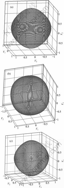
Fig.2 Polar maps of AS (n), 1/AS (n) and �� when ��=0.03: (a) AS (n) polar map; (b) 1/AS (n) polar map; (c) �� polar map
appear at the arris, which is shown in Fig.5. When �� is equal to 0.33, ear will appear at the corner of the graph, and its direction corresponding to the concave surface is not steady and that to the convex surface is steady. The
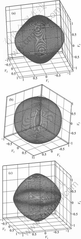
Fig.3 Polar maps of AS (n),1/AS (n) and �� when ��=0.06: (a) AS (n) polar map; (b) 1/AS (n) polar map; (c) �� polar map
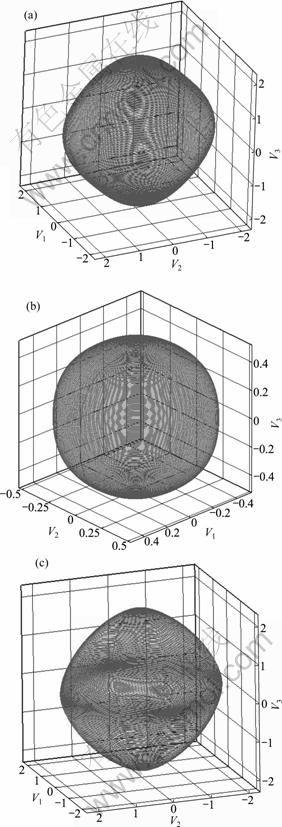
Fig.4 Polar maps of AS (n),1/AS (n) and �� when ��=0.1: (a) AS (n) polar map; (b) 1/AS (n) polar map; (c) �� polar map
directions that are unsteady and metastable will disappear.
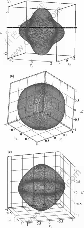
Fig.5 Polar maps of AS (n), 1/AS (n) and �� when ��=0.33: (a) AS (n) polar map; (b) 1/AS (n) polar map; (c) �� polar map
4 Effect of anisotropy on dendrites morphology
Anisotropy factor expresses the anisotropy degree of the interface surface tension, interface thickness and interface dynamics. Anisotropy has important influence
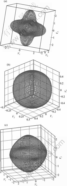
Fig.6 Extremal graph of AS(n),1/AS(n) and �� when ��=0.5: (a) AS(n) polar map; (b) 1/AS(n) polar map; (c) �� polar map
on the dendrite growth.
Fig.7 shows the simulation of the evolutional process of 3D dendrite growth. It can be seen that when t is equal to 500, the original crystal nucleus appear in spherical shape in the 3D state. When t is at the stage between 1 000 and 2 000, it forms six bar trunk along the six apex angle of the square and elongates gradually to the six direction. When t is at the stage between 2 000 and 3 000, the secondary dendrites gradually grow from the six bar trunk, and become more and larger. The primary dendrites change into a viniferous shape because of the growth and getting larger of the secondary dendrites. The radius of the primary dendrites become less and less. Some three cubed dendrites emerge gradually from the root of the secondary dendrites, and they grow larger gradually.
Fig.8 shows the effect of anisotropy on the dendrite growth. It can be seen that with the increase of the anisotropy coefficient, dendrite growth is faster under the same condition.
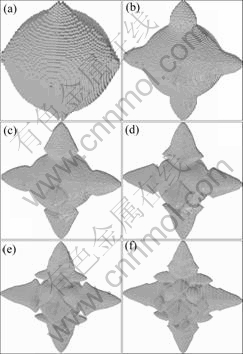
Fig.7 Simulated dendrite growth process at different time steps: (a) t=500; (b) t=1 000; (c) t=1 500; (d) t=2 000; (e) t=2 500; (f) t=3 000
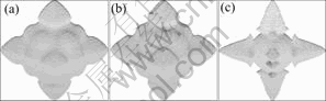
Fig.8 Anisotropy on dendrites growth: (a) �ã�0.05; (b) �ã�0.06; (c) �ã�0.07
5 Conclusions
1) With the change of the interface anisotropy coefficients, the morphology of equilibrium crystals transforms from smooth to appearance of angle. And the corresponding anisotropy factor has a critical value of 0.3 with 3D.
2) The dendrite growth is stable and the interface is smooth when the anisotropy factor is less than the critical value.
3) The interface is unstable, rolling edge appears and growth is discontinuous when anisotropy factor is more than the critical value.
4) With the anisotropy coefficient becoming larger, dendrites grow faster under the same condition.
References
[1] MULLIONS W W, SEKERKA R F. The stability of planar interface during solidification[J]. App Phys, 1964, 35: 444-451.
[2] KESSLER D, LEVINE H. Theory of the Saffman-Taylor finger pattern[J]. Phy Rev A, 1986, 33: 2621-2633.
[3] KESSLER D, LEVINE H. Stability of dendritic crystals[J]. Phy Rev A Lett, 1986, 57: 3069-3702
[4] KESSLER D, LEVINE H. Dendrite growth in a channel[J]. Phy Rev A, 1986, 34: 4980-4987.
[5] MULLIONS W W. Morphological stability of a particle growing by diffusion of heat flow[J]. App Phy, 1963, 34: 323-329.
[6] SAITO Y, WOOD G, HMULLER K. Dendrite crystallization: Numerical study of the one-sided model[J]. Phys Rev Lett, 1987, 58: 1541-1543.
[7] BEN-JACOB E, GOLENFELD N, LANGER J S. Boundary-layer model of pattern formation in solidification[J]. Phys Rev A, 1984, 29: 330-340.
[8] BEN-JACOB E, GOLENFELD N, KOTLIAR B G. Pattern selection in dendrite Solidification[J]. Phys Rev Lett, 1984, 53: 2110-2113.
[9] YOUNG G W, DAVIS S H, BRATTKUS K. Anisotropic interface kinetics and tilted cells in unidirectional solidification[J]. Crystal Growth, 1986, 83: 560-571.
[10] YU Y M, YANG G C, ZHOU D W. Determination of interface width value in phase-field simulation of dendritic growth into undercooled melt[J]. Progress in Natural Science, 2002, 12(3): 103-108.
[11] NESTLER B, WHEELER A A, RATKE L. Phase field model for solidification of a monotectic alloy with convection[J]. Physica D, 1999, 140: 133-154.
[12] LEE S, SUZUKI T. Numerical simulation of isothermal dendritic growth by phase-field model[J]. ISIJ International, 1999, 39(3): 246-252.
[13] KIM S G, KIM W T, SUZUKI T. Interfacial compositions of solid and liquid in a phase-field model with finite interface thickness for isothermal solidification in binary alloys[J]. Phys Rev E, 1998, 58(3): 3316-3323.
[14] ANDERSON D M, MCFADDEN G B, WHEELER A A. A phase field model with convection: Sharp-interface asymptotics[J]. Phys D, 2001, 151: 305-331.
[15] HOU Hua, JU Dong-ying. Numerical simulation for dendrite growth of binary alloy with phase field method[J]. Journal of Materials Science Technology, 2004, 20: 45-48.
[16] MULLIS A M. A study of kinetically limited dendrite growth at high undercooling using phase-field techniques[J]. Acta Materialia, 2003, 51: 1959-1969.
[17] TAKUYA U, ROBERT F S. Phase field simulations of faceted growth for strong anisotropy of kinetic coefficient[J]. Journal of Crystal Growth, 2003, 254: 251-261.
[18] KIM S G, KIM W T. Phase field modeling of dendritic growth with high anisotropy[J]. Journal of Crystal Growth, 2005, 275: e355-e360.
[19] EGGLESTON J J. A phase model for highly anisotropic interfacial energy[J]. Physica D, 2001, 150: 91-103.
[20] LO T S, KARMA A, PLAPP M. Phase-field modeling of microstructure pattern formation during directional solidification of peritectic alloys without morphological instability[J]. Physical Review E, 2001, 63(3): 1504-1520.
[21] ROBERT F S. Equilibrium and growth shapes of crystals: How do they differ and why should we care? [J]. Cryst Res Technol, 2005, 40: 291-30.
(Edited by YANG You-ping)
Foundation item: Project(110218) supported by Program for the Top Young Academic Leaders of Higher Learning Institutions of Shanxi Province, China
Corresponding author: HOU Hua; Tel: +86-351-3557118; E-mail: houhua@263.net
