

Modeling of numerical simulation and experimental verification for carburizing-nitriding quenching process
R. MUKAI1, T. MATSUMOTO2, JU Dong-ying1, 3, T. SUZUKI2, H. SAITO2, Y. ITO4
1. High-Tech Research Center Special Researcher, Saitama Institute of Technology, Fukaya 369-0293, Japan;
2. Department of Mechanical Engineering, Saitama Institute of Technology, Fukaya 369-0293, Japan;
3. Research Center of High Technology, Anshan University of Science and Technology, Anshan 114044, China;
4. Department of Technology Development, Tobuyakin Ltd., Japan
Received 10 April 2006; accepted 25 April 2006
Abstract:
A model considering quantitative effects of diffused carbon and nitrogen gradients and kinetics of phase transformation is presented to examine metallo-thermo-mechanical behavior during carburized and nitrided quenching. Coupled simulation of diffusion, phase transformation and stress/strain provides the final distribution of carbon and nitrogen contents as well as residual stress and distortion. Effects of both transformation and lattice expansion induced by carbon and nitrogen absorption were introduced into calculating the evolution of the internal stress and strain. In order to verify the method and the results, the simulated distributions of carbon and nitrogen content and residual stress/strain of a ring model during carburized and nitrided quenching were compared with the measured data.
Key words:
carburizing; nitriding; quenching; numerical simulation; metallo-thermo-mechanical behavior;
1 Introduction
The present authors have carried out, for these decades, to construct the fundamental framework of ��metallo-thermo-mechanics [1, 2] relevant to describing the coupled fields of metallic structure, temperature and stress/strain occurring in the engineering process incorporating phase transformation such as quenching, welding and casting, and developed some computer simulation codes, HEARTS [1, 3], COSMAP [4] and under developing. Effect of diffused carbon during the carburized quenching is also possible to be simulated by these codes, and the results were presented elsewhere [5].
Nitriding is known as another important process as well as the carburizing among the thermo-chemical surface treatments in engineering practice [6-9]. The technology is widely applied to machine parts such as automotive gears, shafts and so on due to the beneficial effects on fatigue resistance, tribological and anti-corrosion properties. The reasons for the property improvement are ascribed to the compound layers composed of fine nitrides or carbides of alloying elements, and residual surface stresses are also attributed to this process. As a known fact, residual stresses are always accompanied by changes in shape and size of work-piece, which often results in significant distortion of the machine parts. This also leads to undesired effects such as increasing noise from transmission gears. In order to improve such kind of defects, manufacturing engineers need to have a thorough understanding how various process parameters influence the final profiles of carbon/nitrogen, stress/distortion and microstructures of heat-treated components. To do this, in recent years, there have been a great number of experimental and theoretical interests in mathematical description of carburizing and/or nitriding processes [5]. Numerical simulation by the finite element method (FEM), due to its benefit in reducing consuming time and trial-and-error experiments that plague engineers, is looking forward to being used widely in engineering problems. However, in many commercialized programs can not solve some problems on the effect of diffusion of nitrogen or simul-taneous diffusion of carbon and nitrogen on the following thermo-mechanical simulation still remain imperfect.
With respect to this, the numerical modeling for simulating the metallo-thermo-mechanical behavior during carburized and nitrided quenching is developed in this paper. The purpose of the modeling aims to make it capable to calculate not only diffusion of multi-element during chemical treatment but also the evolution of microstructure, stress and distortion during carburized and nitrided quenching by considering the effect of C/N diffusion on distortion and phase transformation kinetics. In order to verify the numerical method, the simulated distributions of carbon and nitrogen contents, temperature and variation of microstructure as well as residual stress/strain of a ring during carburized and nitrided quenching are compared with the measured results.
2 Modeling
The modeling developed by the authors can be used to predict the evolution of temperature, microstructure, stress/distortion and profiles of chemical component such as carbon and nitrogen and so on during some processes of thermochemical treatment and heat treatment. The models involved in the FEM procedure can be divided into four categories of analysis: heat conduction, diffusion of C/N, transformation kinetics and stress/strain analysis by use of elasto-plastic constitutive equations. When the boundary conditions are involved, the prescribed flux boundary conditions are employed.
2.1 Diffusion of nitrogen and carbon
Diffusion equation for nitrogen in nitriding process is simply described by normal diffusion type equation:
![]() (1)
(1)
with boundary condition
![]() (2)
(2)
where N, Nw and rN respectively stand for diffused mass percent, environment potential and internal source of nitrogen. Global diffusivity DN is also assumed to be given by the mixture law as
![]() (3)
(3)
Each constituent DNI(N) is designed to be calculated by the formula as
 (4)
(4)
with the functions f(C, N) and h(gradC, gradN) of carbon and nitrogen concentrations and the gradients, respectively. And QN in Eqn.(4) is the activation energy for diffusing nitrogen, and DNI, 0 and R are material constants. The coefficient of surface reaction rate ��N in Eqn.(2) of nitriding process under partial pressure p(H2) of hydrogen in the mixed gas is given by
![]() (5)
(5)
where ![]() is a constant [5].
is a constant [5].
The equation governing carbon diffusion kinetics can be simply obtainable by exchanging N and C in Eqns. (1)-(4). When the coefficient of surface reaction rate ��C for carbon is decided by using experimental method [6], thev carbon diffusion in steel can be expressed by the following boundary condition,
![]() (6)
(6)
2.2 Heat conduction
The heat conduction equation governing temperature field T is
![]() (7)
(7)
Here, the coupled term rv with mechanical work and latent heat generation is
![]() (8)
(8)
This term is taken into account in the case of quenching, but not for the carburizing or nitriding process.
The heat conduction in Eqn.(7) is possibly solved with heat transfer boundary condition
![]() (9)
(9)
where ��, c and k denote density, specific heat and heat conductivity, respectively. rv is internal heat source, h and Tw mean heat transfer coefficient and environmental temperature on the boundary and ni is u nit normal. The value of![]() , c and k should be calculated according to the mixture rule
, c and k should be calculated according to the mixture rule
![]()
where ![]() is a material property and
is a material property and ![]() is volume fraction of the I-th phase.
is volume fraction of the I-th phase.
2.3 Phase transformation kinetics
The microstructures involved in the present simulation are assumed to be composed of three constituents; austenite, pearlite or bainite and martensite. The diffusion type transformation from austenite to pearlite is calculated based on the modified Johnson- Mehl relation [10]. In this case of carbon steel SCM420, the volume fraction of pearlite ![]() is expressed as
is expressed as
![]() (10)
(10)
![]() (11)
(11)
![]() (12)
(12)
![]() (13)
(13)
where ![]() is mean stress, C and C0 denote current and initial carbon contents and
is mean stress, C and C0 denote current and initial carbon contents and ![]() are some transformation kinetics parameters. Diffusionless transformation is controlled by
are some transformation kinetics parameters. Diffusionless transformation is controlled by
![]()
![]() (14)
(14)
by modified Magee��s rule [11] , where ![]() is the volume fraction of martensite,
is the volume fraction of martensite, ![]() are material parameters. N and
are material parameters. N and ![]() mean the current and iitial nitrogen contents (%) in the nodes, respectively.
mean the current and iitial nitrogen contents (%) in the nodes, respectively.
In the above equations, the effects of C/N profile on transformation kinetics are considered. Due to the small penetrating depth of N atoms and high contents of C in the nitrogen diffusion layer, little pearlite transformation occurs in this layer. It should not matter greatly even though no effect of nitrogen is taken into account in diffusion type transformation kinetics.
2.4 Constitutive equations
Total strain rate ![]() is assumed to be sum of rates of elastic strain
is assumed to be sum of rates of elastic strain ![]() , plastic strain
, plastic strain ![]() , thermal strain
, thermal strain ![]() , transformation strain
, transformation strain ![]() and diffusion induced strain
and diffusion induced strain ![]() of carbon and nitrogen which is newly introduced in this paper.
of carbon and nitrogen which is newly introduced in this paper.
![]() (15)
(15)
Here the four terms are given by
![]() (16)
(16)
![]() (17)
(17)
with yield function
![]() (18)
(18)
![]() (19)
(19)
![]() (20)
(20)
where E and ![]() are elastic modulus and Poisson ratio, T is temperature, and
are elastic modulus and Poisson ratio, T is temperature, and![]() is the dilatation due to the microstructure change from the Jth to Ith phase.
is the dilatation due to the microstructure change from the Jth to Ith phase. ![]() is thermal expansion coefficient of the Ith phase.
is thermal expansion coefficient of the Ith phase.
Compared with the previous constitutive equations of the authors, a new term ![]() in Eqn.(15) due to carbon or nitrogen diffusion is introduced in this paper. When carbon or nitrogen is absorbed as interstitial atoms, the lattice parameters change to induce the volumetric dilatation. Some researchers proposed formulas of the lattice parameters depending on carbon and nitrogen contents. If transformation
in Eqn.(15) due to carbon or nitrogen diffusion is introduced in this paper. When carbon or nitrogen is absorbed as interstitial atoms, the lattice parameters change to induce the volumetric dilatation. Some researchers proposed formulas of the lattice parameters depending on carbon and nitrogen contents. If transformation ![]() occurs between time interval t0 and t due to the diffusion of carbon and nitrogen, the strain
occurs between time interval t0 and t due to the diffusion of carbon and nitrogen, the strain ![]() is
is
 (21)
(21)
where ![]() means the number of Fe atoms in single unit cell of certain microstructure.
means the number of Fe atoms in single unit cell of certain microstructure. ![]() and
and ![]() denote the
denote the ![]() and
and ![]() lattice parameter before and after
lattice parameter before and after ![]() transformation, while ct and Nt are the carbon and nitrogen contents at time t.
transformation, while ct and Nt are the carbon and nitrogen contents at time t.
If no transformation occurs during diffusion of carbon and nitrogen, the microstructure is only composed of austenite. Thus, the strain rate ![]() simply depends on the diffusion rate of carbon and nitrogen in the form as
simply depends on the diffusion rate of carbon and nitrogen in the form as
 (22)
(22)
where a is the lattice parameter of austenite, which is a function of current carbon and nitrogen contents.
3 Materials and condition of experiments and simulation
The steel used in this paper is the carbon steel (JIS-SCM420). The heat pattern is composed of 5 steps, as shown in Fig.1. In the first step, the specimen is heated up to 930 �� from room temperature and then mixed C/N gas is provided with certain carbon and nitrogen potentials, which are w(C)=1.1% and w(N)=0.3% in the present case. The second step is for carburizing and nitriding for 240 min. After that, the
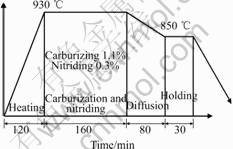
Fig.1 Heat pattern of carbon steel
specimen is cooled to 850 �� for 10 min and then is held at this temperature for 30 min as diffusion period to decrease the gradients of carbon and nitrogen. The final step is for quenching of the specimen into oil quenchant of 60 ��.
The sizes of the ring specimen are shown in Fig.2, in which the holes (No.1-3) are drilled to insert thermocouples for temperature measurement during quenching. Due to the symmetry, the one-fourth of the cross section is used for meshing by 1 809 nodes and1 716 elements by use of quadrilateral iso-parameter elements with four nodes. The thermal and diffusion boundary conditions are both the flux type, and hardness and residual stresses are measured after experiments, the results of which are used to compare with the calculated ones.
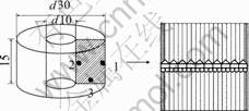
Fig.2 Dimension of carbon steel specimen(mm)
4 Results and discussion
The cooling curves on measured points are shown in Fig.3. Using of identifying method based on measured cooling curves and simulation, the heat transfer coefficients in the surface to near the measured points are identified and shown in Fig.4.
Cooling curves and identified heat transfer coefficient of the ring specimen during quenching process are shown in Figs.3 and 4. Temperatures calculated by the program at the same positions in center and near surface as that in the measurement experiment are compared with the measured values. We could see the calculated temperatures agree well with the measured results.
There is a little discrepancy on surface between both the calculated and measured data, which is regarded
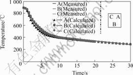
Fig.3 Cooling curves of ring specimen
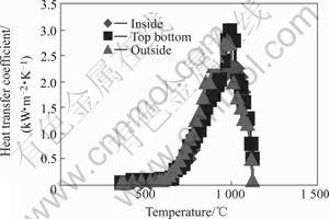
Fig.4 Heat transfer coefficient curves of ring specimen
as mainly originated from surface heat transfer boundary condition. The discrepancy could be decreased by improving the heat exchange coefficient on the surface.
Fig.5 and 6 show the calculated microstructure evolution during quenching with temperature change, which follows that the volume fraction of martensite is higher at certain depth (0.5 mm) than that on the surface in spite of the decrease in cooling rate from surface to center. This is due to the different carbon and nitrogen contents at the corresponding positions.
Fig.7 represents the profile of residual stresses on the middle section of the specimen. The data on the surface agree qualitatively with the measured values by X-ray diffraction method on the surface. The value of axial stress almost equals to that of tangential stress. Fig.8 displays the calculated results of final distortion, which also agree well to the measured displacements in the radial direction. The small discrepancy between the measured and calculated values may be caused by the following factors. Constitutive equations should be the functions of carbon and nitrogen contents, and Fig.7 represents the profile of residual stresses on the middle section of the specimen. The data on the surface agree qualitatively with the measured values by X-ray diffraction method on the surface. The value of axial stress almost equals to that of tangential stress. Fig.8 displays the calculated results of final distortion, which also agree well to the measured displacements in the
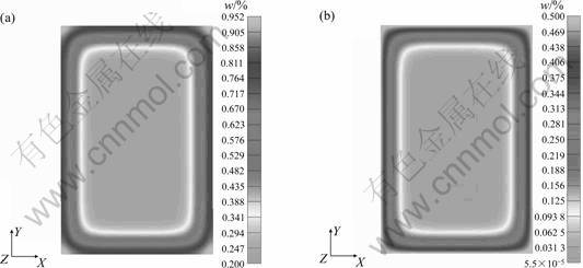
Fig.5 Distribution of content of carbon and nitrogen: (a) Carbon; (B) Nitrogen
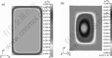
Fig.6 Distribution of content of martensite (a) and bainite (b)
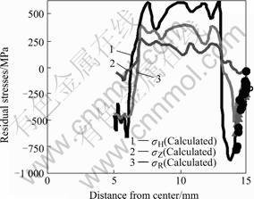
Fig.7 Stress profiles on middle section
radial direction. The small discrepancy between the measured and calculated values may be caused by the following factors: Constitutive equations should be the functions of carbon and nitrogen contents, and transfor- mation plasticity should be added while both effects
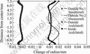
Fig.8 Comparison of distortion
neglected at present in the first approximation. But due to the lack of related experimental results about the effects of carbon and nitrogen contents on the related parameters used in the constitutive equations, they are neglected at present. These factors will be considered in hereafter research and calculations.
5 Conclusions
A mathematical model to predict the carbon and nitrogen contents as well as residual stresses and distortions after carburized and nitrided quenching are proposed in this paper, and finite element implementation is carried out to identify the profiles. The predicted results agree well with the experimental results. This proves that the program can be used effectively to calculate the metallo-thermo-mechanical behavior during heat treatment and chemical treatment. Of course, there are some aspects to be improved, which can be realized by considering the effects of carbon and nitrogen contents on constitutive equations. The models about the interactions between diffusion of nitrogen and carbon also need to be established.
AcknowledgementsThe support provided by High Technology Research Center in Saitama Institute of Technology for this work is gratefully acknowledged.
References[1] INOUE T, JU D Y, ARIMOTO K. Metallo-thermo-mechanical simulation of quenching process-theory and implementation of computer code HEARTS [A]. Proc 1st Int Conf Quenching and Control of Distortion, ASM International[C]. Chicago, 1992.
[2] INOUE T. Inelastic constitutive relationships and applications to some thermo-mechanical processes involving phase transformation, [A]. Hetnarski R B. Thermal Stresses[C]. North-Holland, 1988.
[3] JU D Y, LIU C C. Overview on the microstructure evolution and induced stresses in nitrided chromium steels [A]. Nakonieczny A. Nitriding Technology [C]. Institute of Precision Mechanics, 2003, 209-309.
[4] JU D Y, LIU C C, INOUE T. Numerical modeling and simulation of carburized and nitrided quenching process, [J]. Journal of Materials Processing Technology, 2003, 143: 880-885.
[5] METIN E, OSMAN T. Kinetics of layer growth and multiphase diffusion in ion-nitrided titanium[J]. Metall Trans A, 1989, 20A: 1819-1832.
[6] SUN Y, BELL T. A numerical model of plasma nitriding of low alloy steels [J]. Mater Sci Eng A, 1997, A224: 33-47.
[7] CHRISTAIN J W. The Theory of Transformation in Metals and Alloys: Equlibrium and General Kinetic Theory [M]. 2nd ed. Pergamon: Oxford, 1975: 542-546.
[8] BONGARTZ K. QUADAKKERS W J, SCHULTEN R, NICKEL H. A mathematical model describing carburization in multielement alloy system [J]. Metall Trans A, 1989, 20A: 1021-1027.
[9] ROZENDAL H C, MITTERMEIJER E J, COLIJIN P F, VANDER P J. The development of nitrogen concentration profiles on nitriding iron [J]. Metall Trans A, 1983, 9A: 395.
[10] JOHOSON W A, MEHL R F. Reaction kinetics in processes of nucleation and growth[J]. Trans AIME, 1939, 135: 416-458.
[11] MAGEE C L. Nucleation of Martensite [M]. New York: 1968.
Corresponding author: JU Dong-ying; Tel: +81-48-595-6826; Fax: +81-48-585-5928; E-mail: dyju@sit.ac.jp
