
J. Cent. South Univ. Technol. (2011) 18: 216-222
DOI: 10.1007/s11771-011-0682-x
![]()
Elastoplastic solutions for single piles under combined vertical and lateral loads
ZHANG Lei(����)1, GONG Xiao-nan(������)1, YANG Zhong-xuan(������)2, YU Jian-lin(�Ὠ��)1
1. Key Laboratory of Soft Soils and Geoenvironmental Engineering, Ministry of Education,
Zhejiang University, Hangzhou 310058, China;
2. Department of Civil Engineering, Zhejiang University, Hangzhou 310058, China
? Central South University Press and Springer-Verlag Berlin Heidelberg 2011
Abstract:
In order to improve the reliability of the design and calculation of single piles under the combined vertical and lateral loads, the solutions were presented based on the subgrade reaction method, in which the ultimate soil resistance was considered and the coefficient of subgrade reaction was assumed to be a constant. The corresponding computational program was developed using FORTRAN language. A comparison between the obtained solutions and the model test results was made to show the validity of the obtained solutions. The calculation results indicate that both the maximum lateral displacement and bending moment increase with the increase of the vertical and lateral loads and the pile length above ground, while decrease as the pile stiffness, the coefficient of subgrade reaction and the yielding displacement of soil increase. It is also shown that the pile head condition controls the pile responses and the vertical load may cause the instability problem to the pile. In general, the proposed method can be employed to calculate the pile responses independent of the magnitude of the pile deflection.
Key words:
1 Introduction
It is known that the majority of piles are designed to support either the vertical loads [1-3] due to the self weights and superstructures, or the lateral loads [4-6] engendered by waves, winds, impact of ships, etc. However, in some cases, piles may be subjected to the vertical and lateral loads simultaneously [7]. For laterally loaded piles, the existence of the vertical load can cause the additional bending moment and horizontal displacement, which has been shown by many investigations including the laboratory tests [8-9], field investigations [10] and also 3D finite-element numerical analyses [11-12]. Therefore, the analysis of the responses of the pile under combined vertical and lateral loads is more important than that of the pile only under lateral loads. Based on the subgrade reaction method [13], TANG and WU [14] obtained the analytical solutions for the single pile under combined vertical and lateral loads by assuming the coefficient of subgrade reaction to be a constant. By assuming a linear increase of the coefficient of subgrade reaction with the depth, LI et al [15] obtained the power-progression solutions, while HAN and FROST [16] used the variational method to investigate the pile responses and analyze the influence of the vertical load on lateral responses of the pile. However, all the above methods [14-16] are valid only when the pile deflection is very small, which is mainly attributed to the assumption that the soil resistance is proportional to the horizontal displacement of the pile. In the cases of the offshore and coastal applications, the applied loads are significantly high, and the soil surrounding the pile cannot be simply represented by a series of independent springs. With the increase of the applied loads, the maximum (ultimate) resistance of the soil along the pile shaft is gradually mobilized, that is, some parts of the soil have already yielded [17-18]. For the laterally loaded pile, HSIUNG et al [19-20] and GUO [21-22] obtained the analytical solutions, in which the ultimate soil resistance was considered, by assuming the coefficient of subgrade reaction to be a constant. However, the analysis of the single pile under combined vertical and lateral loads based on the subgrade reaction method, in which the ultimate soil resistance was considered, has less been reported in the literature so far.
In this work, the elastoplastic solutions for a single pile subjected to the combined vertical and lateral loads and partially embedded in a homogeneous medium were obtained and implemented by a computational program developed using FORTRAN language. A comparison was made between the obtained solutions and the model test results, and the influence of loads and some parameters of the pile and the soil on pile responses was analyzed accordingly.
2 Differential equations and solutions
2.1 Analytical model and assumptions
The problem of a partially embedded pile under combined vertical and lateral loads is schematically described in Fig.1, where Np, Qp and Mp are the vertical load, the horizontal load and the moment load, respectively; H1, H2 and H3 are the pile lengths above the ground, in the plastic zone of soil and in the elastic zone of soil, respectively, and accordingly the domain is divided into three sub-domains with different coordinate systems. For convenience, the subscripts G, S and R denote the pile shafts above the ground and in the plastic and elastic zones of soil, respectively. The distributed load acting on the pile shaft above the ground is assumed to be q1(x)=k1+k2x, where k1 and k2 are the coefficients of the distributed load.
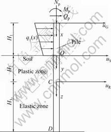
Fig.1 Schematic diagram of pile under combined vertical and lateral loads
The pile-soil interaction model is shown in Fig.2(a), where N0, Q0 and M0 are the vertical load, the horizontal load and the moment load, respectively, which are transmitted from the pile shaft above the ground; k=k0b, in which k0 and b are the coefficient of subgrade reaction and the pile width, respectively; pu=ku*, in which pu and
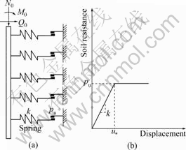
Fig.2 Pile-soil interaction analysis: (a) Load transfer model; (b) Relationship between soil resistance and displacement
u* are the ultimate resistance and the yielding displacement of soil, respectively. The value of u* can be estimated from the p-y curves for the laterally loaded pile. According to Ref.[17], the yielding displacement of the clay can be calculated by
![]() (1)
(1)
where ��c is the strain, usually between 0.005 and 0.02 [17]. The yielding displacement of the sand [18] can be obtained by
![]() (2)
(2)
The relationship between the soil resistance and the lateral displacement is shown in Fig.2(b), and the following assumptions are adopted:
1) The pile is considered as an Euler-Bernoulli beam and the pile length in the elastic zone exceeds the critical length lc, beyond which the pile behaves as if it were infinitely long. According to Ref.[23], the critical length is given by
![]() (3)
(3)
where EI is the flexural stiffness of the pile.
2) The soil surrounding the pile is treated as an idealized elastoplastic medium and represented by a series of independent springs and sliders, as shown in Fig.2(a). In the elastic stage of soil, the soil resistance p is assumed to be proportional to the horizontal displacement u with the factor k. Once the horizontal displacement exceeds the yielding displacement u*, the soil resistance remains constant but the displacement can increase continuously.
3) The yielding of soil can only occur from the ground level, and progress downwards [19-22].
4) The influence of the friction along the pile shaft and the self weight of the pile on pile responses is expected to be small and can be neglected, such that the axial force of the pile is equal to the vertical load Np.
5) The axial force of the pile is less than ![]() [14].
[14].
6) The vertical load has no effect on the ability of the soil to resist lateral deflection.
2.2 Differential equations
The sign conventions are as follows. The displacement is positive when rightward; the rotation angle is positive when counterclockwise with respect to the negative z axis; the bending moment is positive when it produces compression in the right part of the pile; the shear force is positive when it spins the object of study clockwise. Based on the theory of beam bending under combined axial and lateral loads, the differential equation for the pile deflection above the ground is
![]() (4)
(4)
where uG is the displacement of the pile at a depth x.
Similarly, the differential equation for the pile deflection in the plastic zone is
![]() (5)
(5)
where uS is the displacement of the pile at a depth y.
And the differential equation for the pile deflection in the elastic zone is
![]() (6)
(6)
where uR is the displacement of the pile at a depth z.
2.3 Solutions
It is known that the rotation angle of the pile, ��= du/dzD, where u and zD are the displacement and the vertical axis of the pile (zD is positive downwards),
respectively; the bending moment, M=![]() and the shear force,
and the shear force,![]() Therefore, by solving
Therefore, by solving
Eq.(4) and using the relationships between the displacement and the other pile responses including the rotation angle, the bending moment and the shear force, the solution for the pile shaft above the ground is
![]() (7)
(7)
where UG=[uG, ��G, MG, QG] T in which ��G, MG and QG are the rotation angle, the bending moment and the shear force of the pile at a depth x, respectively; Up=[up, ��p, Mp, Qp] T in which up and ��p are the displacement and the rotation angle of the pile head, respectively;
 ;
;
 ;
;
![]()
Similarly, the solution for the pile shaft in the plastic zone is
![]() (8)
(8)
where ![]() in which ��S, MS and QS are the rotation angle, the bending moment and the shear force of the pile at a depth y, respectively; U0=
in which ��S, MS and QS are the rotation angle, the bending moment and the shear force of the pile at a depth y, respectively; U0= ![]() in which u0 and ��0 are the displacement and the rotation angle of the pile at the ground surface, respectively;
in which u0 and ��0 are the displacement and the rotation angle of the pile at the ground surface, respectively;
 ;
;
 .
.
And the solution for the pile shaft in the elastic zone is
![]() (9)
(9)
where ![]() in which ��R, MR and QR are the rotation angle, the bending moment and the shear force of the pile at a depth z, respectively;
in which ��R, MR and QR are the rotation angle, the bending moment and the shear force of the pile at a depth z, respectively; ![]() in which uc and ��c are the displacement and the rotation angle of the pile at point C (in Fig.1), respectively;
in which uc and ��c are the displacement and the rotation angle of the pile at point C (in Fig.1), respectively;
 ;
;
![]() ;
; ![]() ;
; ![]() ;
;
![]()
![]()
![]()
![]()
Therefore, once the pile responses at the pile head, the ground surface and point C are determined, the pile responses at any point can be established using Eqs.(7), (8) and (9). Using the known pile responses at the pile head and the continuity of pile responses, the unknown pile responses at the pile head can be determined by matrix operations, and then the pile responses at the ground surface and point C can be determined using the continuity principle. The pile length in the plastic zone can be determined by the dichotomy method. In addition, when designing pile foundations for resisting the combined vertical and lateral loads, the maximum lateral displacement and bending moment are the key parameters. The maximum lateral displacement occurs at the pile head and has already been obtained, while the maximum bending moment can be obtained by comparing the bending moment at the pile head with that at the point where the derivative of the bending moment is zero, which can also be found by the dichotomy method.
3 Validation
Based on the obtained solutions, the computational program was developed using FORTRAN language. In the following, the comparison between the obtained solutions and the model test results is described to validate the obtained solutions. WU and ZHAO [24] reported a free-head aluminum pipe pile with the outer diameter of 16 mm, the thickness of 2 mm and the total length of 1.1 m, which was partially embedded in the sand. The flexural stiffness EI=187 N��m2, and no distributed load or moment load was applied. Based on Eq.(2), the yielding displacement of soil u*=0.6 mm. The lateral displacements at the ground surface u0 and the maximum bending moments Mmax obtained by the two different methods are listed in Table 1, and a good agreement between the calculated and the test results could be obtained.
4 Parametric study of influential factors
4.1 Numerical example of bridge pild foundation
In order to study the influence of a number of factors such as loads, pile head condition, yielding displacement of soil, pile stiffness, pile length above ground and coefficient of subgrade reaction on the maximum lateral displacement and bending moment of the long pile subjected to combined vertical and lateral loads, a numerical example of a bridge pile foundation is given here. The total pile length is 60 m, the pile head condition is free, the pile length above ground H1=20 m, the pile diameter b=1.8 m, the pile stiffness EI=927.5�� 104 kN��m2, the coefficient of subgrade reaction k0= 40 MN/m3, the yielding displacement of soil u*=1 cm, the horizontal load Qp=500 kN, the moment load Mp= 600 kN��m, the vertical load Np=10 MN, and no distributed load is applied on the pile shaft above the ground.
4.2 Influence of applied loads (Qp, Mp and Np) and pile head condition on pile responses
The relationships between the pile responses and the vertical load corresponding to different lateral loads and pile head conditions are shown in Fig.3. The computed results show that both the maximum lateral displacement and bending moment of the free-head pile increase with the increase of the horizontal load and the moment load. The vertical load can cause the additional bending moment and horizontal displacement, and the influence is minor when the vertical load is small. However, with the increase of the vertical load, it becomes more remarkable. Taking a free-head pile as an example which is subjected to a horizontal load of 500 kN and a moment load of 2 MN��m, when the vertical load increases from 0.1 kN to 18 MN and from 18 MN to 20.551 MN, the
Table 1 Comparison between calculated and test results
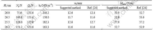
maximum lateral displacement increases by 635.31 and 1 191.48 mm, respectively; and the maximum bending moment increases by 16 629.79 and 23 853.14 kN��m, respectively. It is noted that at the later stage of the application of the vertical load, the maximum lateral displacement and bending moment increase sharply with the increase of the vertical load, and the pile may be unstable, which is consistent with the result reported by HAN and FROST [16]. The calculation results also indicate that the additional bending moment and horizontal displacement increase with the increase of the lateral load, that is, the greater the lateral deflection is, the more remarkable the influence of the vertical load. The pile head condition of the fixed-head pile can offer a moment load, which not only prevents the pile head from rotating but also reduces the lateral displacement of the pile. Therefore, the pile head condition plays a very important role in pile responses. As shown in Fig.3, the maximum lateral displacement and bending moment of the fixed-head pile increase slightly with the increase of the vertical load. However, with the further increase of the vertical load, they can also increase significantly with the increase of the vertical load and finally the pile will
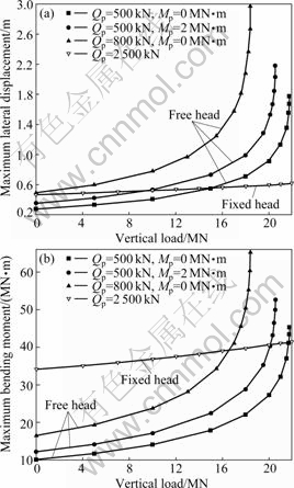
Fig.3 Relationships between pile responses and vertical load corresponding to different lateral loads and pile head conditions: (a) Maximum lateral displacement; (b) Maximum bending moment
also be unstable when the vertical load is great enough, which is not presented in Fig.3.
4.3 Influence of yielding displacement of soil (u*) and pile stiffness (EI) on pile responses
The relationships between the pile responses and the yielding displacement of soil corresponding to different values of the pile stiffness are shown in Fig.4. It can be seen that both the maximum lateral displacement and bending moment decrease with the increase of EI, which is due to the fact that the pile with higher flexibility has higher resistance to the lateral deflection. It can also be seen that both the maximum lateral displacement and bending moment decrease with the increase of u*, and the effect of u* on pile responses becomes less important as u* increases. For the curves corresponding to the pile stiffness of 7��106 kN��m2, when u* increases from 4 mm to 9 mm and from 9 mm to 14 mm, the maximum lateral displacement decreases by 704.24 and 103.73 mm, respectively; and the maximum bending moment decreases by 6 240.70 and 985.46 kN��m, respectively. The reason is that when u* increases, the ultimate soil resistance increases, while the pile length in the plastic
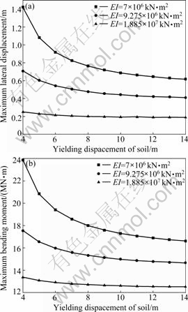
Fig.4 Relationships between pile responses and yielding displacement of soil corresponding to different values of pile stiffness: (a) Maximum lateral displacement; (b) Maximum bending moment
zone decreases. The curves presented in Fig.4 also show that the effect of u* on pile responses becomes less important with the increase of EI. When u* increases from 4 mm to 14 mm, the maximum lateral displacement of the pile having the flexural rigidity of 7��106 kN��m2 and that of the pile having the flexural rigidity of 1.885��107 decrease by 56.78% and 24.84%, respectively; and the maximum bending moment of the pile having the flexural rigidity of 7��106 kN��m2 and that of the pile having the flexural rigidity of 1.885��107 kN��m2 decrease by 30.32% and 6.32%, respectively.
4.4 Influence of pile length above ground (H1) and coefficient of subgrade reaction (k0) on pile responses
The relationships between the pile responses and the pile length above ground corresponding to different values of the coefficient of subgrade reaction are shown in Fig.5. According to the relationship between the soil resistance and the displacement described in Fig.2(b), the soil with a higher k0 can offer a higher resistance against the pile, therefore both the maximum lateral displacement and bending moment decrease with the
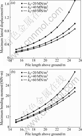
Fig.5 Relationships between pile responses and pile length above ground corresponding to different values of coefficient of subgrade reaction: (a) Maximum lateral displacement; (b) Maximum bending moment
increase of k0. It is clear that both the maximum lateral displacement and bending moment increase with the increase of H1. For instance, for the curves corresponding to the coefficient of subgrade reaction of 20 MN/m3, when the pile length above the ground increases from 15 m to 25 m, the maximum lateral displacement and bending moment increase by 559.73% and 168.89%, respectively. This is because the lateral deflection of the pile above the ground cannot be restricted by the soil. Fig.5 also shows that the influence of H1 on pile responses becomes more significant when H1 increases, meaning that the determination of the pile length above the ground is crucial in the design of the pile foundation when subjected to the combined vertical and lateral loads.
5 Conclusions
1) Based on the subgrade reaction method, the solutions of the responses of the single pile under combined vertical and lateral loads were presented, in which the soil was simplified as a series of independent springs and sliders and the coefficient of subgrade reaction was assumed to be a constant. Therefore, the suggested method can be employed to calculate the pile responses independent of the magnitude of the pile deflection. The comparison was made between the obtained solutions and the model test results, and a very close agreement is found to ensure the validity of the obtained solutions.
2) Both the maximum lateral displacement and bending moment increase with the increase of the lateral loads. The additional bending moment and horizontal displacement caused by the vertical load increase with the increase of the lateral loads. When the vertical load is great enough, the pile may be unstable. Consequently, both the lateral and vertical loads should be taken into account seriously when designing piles under combined loads.
3) The maximum lateral displacement and bending moment decrease with the increase of the coefficient of subgrade reaction and the yielding displacement of soil. Therefore, the bearing capacity of the pile can be effectively enhanced by improving the mechanical properties of the soil surrounding the pile.
4) The maximum lateral displacement and bending moment increase with the increase of the pile length above ground, but decrease with the increase of the pile stiffness. Thus, the determinations of the cross section geometry, the material of the pile and the pile length above the ground are crucial when designing piles for resisting the combined loads.
5) The pile head condition controls the pile responses. Therefore, a reasonable determination of the pile head condition is very important when calculating pile responses.
References
[1] HALDAR S, SIVAKUMAR G L. Load resistance factor design of axially loaded pile based on load test results [J]. Journal of Geotechnical and Geoenvironmental Engineering, ASCE, 2008, 134(8): 1106-1117.
[2] COMODROMOS E M, BAREKA S V. Response evaluation of axially loaded fixed-head pile groups in clayey soils [J]. International Journal for Numerical and Analytical Methods in Geomechanics, 2009, 33(17): 1839-1865.
[3] SEO H, YILDIRIM I Z, PREZZI M. Assessment of the axial load response of an H pile driven in multilayered soil [J]. Journal of Geotechnical and Geoenvironmental Engineering, ASCE, 2009, 135(12): 1789-1804.
[4] BASU D, SALGADO R. Analysis of laterally loaded piles with rectangular cross sections embedded in layered soil [J]. International Journal for Numerical and Analytical Methods in Geomechanics, 2008, 32(7): 721-744.
[5] CHANDRASEKARAN S S, BOOMINATHAN A, DODAGOUDAR G R. Group interaction effects on laterally loaded piles in clay [J]. Journal of Geotechnical and Geoenvironmental Engineering, ASCE, 2010, 136(4): 573-582.
[6] KODIKARA J, HAQUE A, LEE K Y. Theoretical p-y curves for laterally loaded single piles in undrained clay using Bezier curves [J]. Journal of Geotechnical and Geoenvironmental Engineering, ASCE, 2010, 136(1): 265-268.
[7] KARTHIGEYAN S, RAMAKRISHNA V V G S T, RAJAGOPAL K. Influence of vertical load on the lateral response of piles in sand [J]. Computers and Geotechnics, 2006, 33(2): 121-131.
[8] ANAGNOSTOPOULOS C, GEORGIADIS M. Interaction of axial and lateral pile responses [J]. Journal of Geotechnical Engineering, ASCE, 1993, 119(4): 793-798.
[9] HUANG Fu-ming, WANG You-qing, ZHANG Jun. Behavior of pile under combined axial and lateral loading [J]. Journal of Harbin Institute of Technology, 2003, 35(6): 743-746. (in Chinese)
[10] ZHUKOV N V, BALOV I L. Investigation of the effect of a vertical surcharge on horizontal displacements and resistance of pile columns to horizontal loads [J]. Journal of the Geotechnical Engineering Division, ASCE, 1978, 15(1): 16-21.
[11] KARTHIGEYAN S, RAMAKRISHNA V V G S T, RAJAGOPAL K. Numerical investigation of the effect of vertical load on the lateral response of piles [J]. Journal of Geotechnical and Geoenvironmental Engineering, ASCE, 2007, 133(5): 512-521.
[12] SHAHROUR I, MEIMON Y. Analysis of the behavior of offshore piles under inclined loads [C]// Proceedings of the International Conference on Deep Foundations. Paris: ENPC, 1991: 277-284.
[13] FAN C C, LONG J H. Assessment of existing methods for predicting soil response of laterally loaded piles in sand [J]. Computers and Geotechnics, 2005, 32(4): 274-289.
[14] TANG Ye-qing, WU Qing-sun. Calculation methods and cases for piles [M]. Beijing: China Railway Publishing House, 1984: 167-169. (in Chinese)
[15] LI Wei-zhe, ZHAO Ming-hua, SHAN Yuan-ming, YANG Ming-hui. Analysis of single pile under eccentric and inclined loading [J]. Central South Highway Engineering, 2005, 30(3): 53-57. (in Chinese)
[16] HAN J, FROST J D. Load-deflection response of transversely isotropic piles under lateral loads [J]. International Journal For Numerical and Analytical Methods in Geomechanics, 2000, 24(5): 509-529.
[17] MATLOCK H. Correlations for design of laterally loaded piles in soft clay [C]// Proceedings of the Second Annual Offshore Technology Conference. Houston: North Central Expressway, 1970: 577-594.
[18] REESE L C, COX W R, KOOP F D. Analysis of laterally loaded piles in sand [C]// Proceedings of the Sixth Annual Offshore Technology Conference. Houston: North Central Expressway, 1974: 473-483.
[19] HSIUNG Y M. Theoretical elastic-plastic solution for laterally loaded piles [J]. Journal of Geotechnical and Geoenvironmental Engineering, ASCE, 2003, 129(5): 475-480.
[20] HSIUNG Y M, CHEN S S, CHOU Y C. Analytical solution for piles supporting combined lateral loads [J]. Journal of Geotechnical and Geoenvironmental Engineering, ASCE, 2006, 132(10): 1315-1324.
[21] GUO W D. On limiting force profile, slip depth and response of lateral piles [J]. Computers and Geotechnics, 2006, 33(1): 47-67.
[22] GUO W D. Nonlinear response of laterally loaded piles and pile groups [J]. International Journal for Numerical and Analytical Methods in Geomechanics, 2009, 33(7): 879-914.
[23] DAVISSON M T, ROBINSON K E. Bending and buckling of partially embedded piles [C]// Proceedings of the Sixth International Conference on Soil Mechanics and Foundation Engineering. Montreal: University of Toronto Press, 1965: 243-246.
[24] WU Ming, ZHAO Ming-hua. Study on pile-soil interaction under large deflection and its model test [J]. Chinese Journal of Geotechnical Engineering, 2001, 23(4): 436-440. (in Chinese)
Foundation item: Projects(50708093, 50808159) supported by the National Natural Science Foundation of China
Received date: 2010-01-31; Accepted date: 2010-05-13
Corresponding author: YANG Zhong-xuan, Associate Professor, PhD; Tel: +86-571-88208476; E-mail: zxyang@zju.edu.cn
