
J. Cent. South Univ. (2017) 24: 1379-1386
DOI: 10.1007/s11771-017-3542-5

Characteristics and mechanism investigation on drag reduction of oblique riblets
GU Yun-qing(������)1, FAN Tian-xing(������)1, MOU Jie-gang(IJ���)1,
WU Deng-hao(����)2, ZHENG Shui-hua(֣ˮ��)1, Evan Wang3
1. College of Mechanical and Engineering, Zhejiang University of Technology, Hangzhou 310014, China;
2. Zhijiang College, Zhejiang University of Technology, Hangzhou 310024, China;
3. Institute National Polytechnique of Grenoble, Joseph Fourier University, Grenoble 38031, France
 Central South University Press and Springer-Verlag Berlin Heidelberg 2017
Abstract:
This work primarily focuses on the drag reduction characteristics and mechanism investigation of oblique riblets. First, a calculation model of the oblique riblets surface is established, and Reynolds stress model (RSM) turbulence model is used for numerical simulation of the oblique riblets flow field. Subsequently, the influence of inclination angle between flow direction and arrangement direction of riblets on friction resistance and drag reduction rate is further analyzed. Through the investigation of the distribution of shear stress, pressure stress and velocity in oblique riblets boundary layer, the oblique riblets drag reduction mechanism is finally revealed. Results show that, with increase of velocity and inclination angle, the pressure resistance increases obviously, along with the decreasing of the viscous resistance distinctly. The maximum drag reduction rate of the oblique riblets is 7.33%. Moreover, when the inclination angle increases, the wall shear stress reduces on oblique riblets surface; while differential pressure increases at both sides of oblique riblets tips. In addition, when inclination angle is small, the secondary vortex at oblique riblets tips will disappear soon. New vortices will be formed inside the oblique riblets and cause the decrease of viscosity resistance. Thus, oblique riblets show a better drag reduction effect and have an effective control on boundary layer.
Key words:
oblique riblets; drag reduction; Reynolds stress model (RSM); secondary vortex; numerical simulation��
1 Introduction
Due to the shortage of energy, people pay more attention to the energy efficiency. In terms of transportation, the surface friction resistance holds a large proportion in the total resistance. Surface friction in general accounts for a great proportion in total kinetic resistance, more than 60% for a cargo ship [1]. And in the transportation, the most flow is in the turbulent condition. The resistance of the moving body is derived from boundary layer, especially from the turbulent boundary layer. So, boundary layer in the turbulent condition is researched. The phenomena such as coherent structures, transition and burst occurring in the process of turbulence are in-depth analyzed [2]. It is helpful to reduce wall friction resistance and improve energy efficiency.
In the 1960s and 1970s, WALSH et al [3] found that riblets can achieve a drag reduction effect. It broke the thought that the smoother the surface, the fewer the resistance. It also caused the wide attention by researchers. LEE et al [4, 5] studied cylinder with a V-grooved micro-riblets film by particle image velocimetry (PIV) and spanwise vortices. STENZEL et al [6] applied riblets on the turbine blades to achieve the goal of drag reduction. CHAMORRO et al [7] applied riblets on the airfoil and studied wear characteristics on the airfoil which has riblets structure. NUGROHO et al [8] arranged riblets in a ��herringbone�� pattern, did the experiment in an open-return blower wind tunnel and analyzed the influence of riblets on boundary layer. DEAN and BHUSHAN [9] numerically simulated the drag reduction of different shape riblets. PEET et al [10] restructured two kinds of riblets and researched their drag reduction performance by numerical simulation. STALIO and NOBILE [11] showed the secondary vortex by using direct numerical simulation (DNS), and revealed the influence of riblets on heat transfer. The results show that the main reason that riblets can decrease resistance is the secondary vortex in riblets tips and secondary vortex makes low speed, quiet fluid exist in the riblets [12].
The current research of riblets drag reduction mostly focused on the downstream [13]. In the actual application, there will be inevitably a certain inclination angle between flow direction and riblets. The inclination angle has a direct impact on the flow stability of the boundary layer. It will affect coherent structures on boundary layer. Besides, it will make the difference of momentum transfer between inner fluid layers and turbulent boundary layer and lead to different drag reduction effect on the riblets surface at last. Based on this, the calculation model of oblique riblets surface is established. The drag reduction characteristics of oblique riblets and drag reduction mechanism are studied by numerical simulation.
2 Model establishment and parameter settings
2.1 Calculation model
Riblets are arranged along downstream (x direction). The direction of fluid velocity is changed. The inclination angle is formed between direction of the velocity and arrangement direction of the riblets. The numerical calculation model is shown in Fig. 1. In addition, Lx, Ly, Lz are length, height and width of the model, respectively, Lx =60 mm, Ly=16 mm, Lz=0.16 mm; s and h are spacing and height of riblets, respectively; U is the mean velocity of flow field. In order to save computing resources, the smooth surface and riblets surface are calculated in the same model, which means that the opposite position of the riblets surface is the smooth surface.
The flow field of the calculation model is analyzed, including Reynolds number Re,
 (1)
(1)
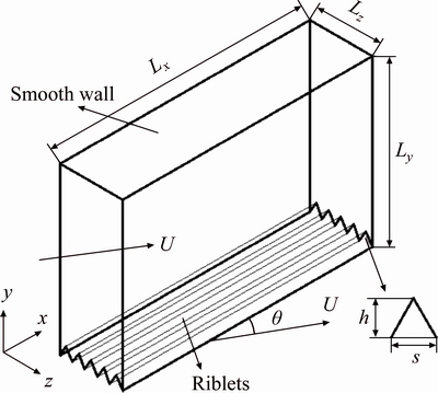
Fig. 1 Structure model of riblets
the theory smooth friction coefficient Cf,
 (2)
(2)
non-dimensional riblets width s+,
 (3)
(3)
and non-dimensional riblets height h+,
 (4)
(4)
where v is the water kinematic viscosity. Equation (2) is a revised formula by experiments, whose scope of application is Re=5��105-2��107.
The riblets have drag reduction effect when non- dimensional riblets height h+ ��25 and non-dimensional riblets width s+��30 [14]. From Eqs. (1)-(4), structure parameters of riblets surface in the calculation model are s=0.02 mm, h=0.0173 mm.
2.2 Control equation and turbulence model
The solution of the flow field meets the following control equation [15]:
 (5)
(5)
where �� is the fluid density; t is the time; u is the velocity vector; f is the general dependent variable; Sf is the generalized source term and ��f is the generalized diffusion coefficient.
Reynolds stress model (RSM) can truly simulate the actual turbulence anisotropy characteristic and can better reflect the tiny feature such as the vortices. during the turbulence flow [16]. Combined with the complexity and diversity of riblets surface near turbulence wall, RSM is selected to simulate near wall turbulent flow field on the riblets surface.
The Reynolds stress transport equation is
 (6)
(6)
where  is local time; Cij is convection; Dij is turbulence diffusion; CM, ,ij is molecular diffusion; Pij is stress production; fij is pressure strain; ��ij is dissipation and Fij is production by system rotation. Specific forms of each symbol see Ref. [17].
2.3 Meshes generation and boundary condition settings
To accurately simulate the micro flow field, a fine mesh is needed near wall flow field; at the same time, considering to save the operation time and improve computing efficiency, the number of grids also needs to be controlled. Thus, in order to guarantee computational precision, keep the micro virtual flow field characteristics better and reduce the amount of calculation, the way boundary layer mesh taken is size function method. It means that the grid is intensive near the wall, sparse away from the wall. The first layer size of mesh is 1.5 ��m. And increase ratio is 1.05. The maximum mesh size is 0.8 mm. The total amount of mesh is 170040. Meshes generation is shown in Fig. 2.
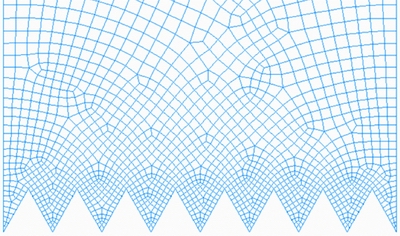
Fig. 2 Meshes generation
In the numerical calculation, the discretization method is based on the finite volume method. The residuals are set to 1��10-4; solution method is implicit solver based on pressure; discretization is second order upwind which has better stability and higher precision; operating condition is normal temperature, atmospheric pressure; the fluid is water. Four planes between smooth surface and riblets surfaces are set to periodic boundary conditions [18]. The given mass flow rate is calculated by the velocity components in the x and z directions multiplying the flow cross-section and the density. ��=0��-45�� (interval is 5��), U=10-25 m/s (interval is 5 m/s).
2.4 Comparison between numerical simulation and theoretical analysis
To testify the accuracy of the turbulent boundary layer simulation based on RSM, the smooth surface friction coefficient based on RSM is compared with the theoretical value. Theoretical smooth surface friction coefficient is calculated by Eq. (2). In these numerical calculation, Re=5.97��105-1.49��106, which is in the scope of Eq. (2). The smooth surface shear stress �� based on RSM is substituted into Eq.(7) [19].
 (7)
(7)
Comparison of the results between RSM and theory is shown in Fig. 3. Smooth surface friction coefficient based on RSM calculation is consistent with theoretical smooth surface friction coefficient. And the smooth surface friction coefficient is close to theoretical value under each Re. The error is about 1%. And the error decreases with the increase of Re. According to the analysis above, the smooth surface friction coefficient based on RSM is identical with the results calculated by Prandtl boundary layer friction coefficient formula. So, it is feasible to simulate a flat plate boundary layer flow with RSM.
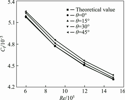
Fig. 3 Comparison of results between RSM and theory
3 Drag reduction characteristics of oblique riblets surface
Riblets surface drag reduction rate �� is
 (8)
(8)
 (9)
(9)
where Fs is viscous resistance of the smooth surface; Fd is total resistance of the oblique riblets surface; Fp is pressure resistance of the oblique riblets surface and Ff is viscous resistance of the oblique riblets surface.
3.1 Oblique riblets surface resistance analysis
Figure 4 shows the comparison between the total resistance of smooth surface Fs and the total resistance of oblique riblets surface Fd. Figure 4 shows that, when �� is determined, the increase of U, Fs, shows an increasing trend; when U is determined, with the increase of ��, the change of the Fs is not obvious, which indicates that the change of �� has little impact on resistance of smooth surface. When U=25 m/s, ��=45��, the maximum Fs is 13.1 mN. The resistance of oblique riblets surface is not as the same as resistance of smooth surface. The resistance of the smooth surface mainly comes from the viscous resistance. But the resistance of oblique riblets surface mainly makes up of viscosity resistance and pressure resistance. When ��=0��, the resistance of oblique riblets surface is viscosity resistance; When ��>0��, pressure resistance will be formed at the oblique riblets surface. When U=25 m/s, ��=0��, the maximum Fd is 12.5 mN. According to the analysis above, the maximum oblique riblets surface resistance is less than the maximum smooth surface resistance.
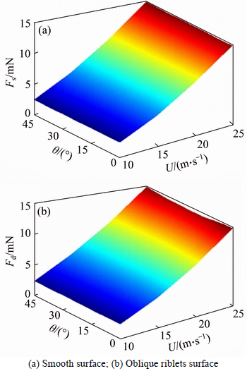
Fig. 4 Resistance in smooth surface and oblique riblets:
Figure 5(a) shows the distribution of pressure resistance Fp and viscous resistance Ff on the oblique riblets. Figure 5(a) shows, when ��=0��, Fp=0; when �� is determined, with the increase of U, Fp gradually increases. When �� is large, Fp gradient changes a lot. When U is determined, with the increase of ��, Fp gradually increases. When U is small, �� and Fp show an approximate linear relationship. The change of U, �� and Fp presents an approximate parabolic relationship. With the increase of ��, U has a large influence on Fp. When U=25 m/s, ��=25��, the maximum Fp is 6.83 mN.
Figure 5(b) shows that when �� is determined, with the increase of U, Ff sharply rises. When U is determined, the increase of �� makes Ff decrease. When ��=45�� U=10 m/s, the minimum Ff is 1.13 mN. When U is small, �� and Ff present an approximate linear relationship. With the increase of U, �� and Ff show an approximate parabolic relationship. When U=25 m/s, ��=0��, the maximum Ff is 12.5 mN.
3.2 Drag reduction rate analysis of oblique riblets
Based on the analysis of the viscosity resistance and pressure resistance between smooth surface and oblique riblets surface, drag reduction rate �� is calculated under different U and ��. Figure 6 shows the distribution of drag reduction rate �� on the oblique riblets surface. It presents that oblique riblets surface has a better drag reduction effect; When U is determined, except that when U=10 m/s, �� decreases with the increase of ��. In the rest of the case, �� increases at first and then decreases with the increase of ��. And under each U, the maximum �� shows an increase trend. At a certain ��, with the change of U, �� is not the same. When �� is small, �� shows a rapidly decrease trend; When �� is large, with the increase of U, �� shows a slowly rising trend. The maximum �� on the oblique riblets surface appears when U=25 m/s, ��=25��. At this moment, Ff=9.89 mN, Fp=2.14 mN, Fd=1.20 mN, ��max= 7.33%. When U=15 m/s, ��=15��, the maximum �� appears, ��max=6.02%.

Fig. 5 Resistance of oblique riblets:
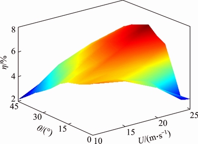
Fig. 6 Drag reduction rate of oblique riblets
4 Drag reduction mechanism of oblique riblets surface
In actual application, large container ship speed is 20-28 knots; large nuclear-powered aircraft carrier��s top speed can be up to 32-35 knots; ordinary warship��s speed is 20-30 knots; large cruise liner��s speed is equal to large container ship��s speed. Ship speed range is roughly about 15 m/s [20, 21]. So in the analysis, U=15 m/s is chosen as a research object of the oblique riblets drag reduction mechanism.
4.1 Analysis of boundary layer shear stress
Figure 7 shows a shear stress �� contour of oblique riblets surface. The maximum shear stress appears in the riblets tips. From the riblets tips to the valleys, wall shear stress gradually decreases. And it is close to zero at the riblets valleys. Under the different inclination angles, the wall shear stress has a similar trend. The riblets tips are the regions of the wall shear stress concentration. It indicates that the flow nearby riblets tips is severe. It contains turbulent kinetic energy and momentum transfer can��t be ignored at riblets tips. This phenomenon is caused by the secondary vortex existing nearby riblets tips.
To analyze wall shear stress under different inclination angles, with the increase of ��, wall shear stress shows a decrease trend. The wall shear stress at the riblets tips has diminished in some extent. The pressure gradient at the riblets tips has changed much when ��=0�� and ��=45��. When ��=0��, pressure gradient at the riblets tips is much larger. When ��=45��, the pressure gradient at the riblets tips is smaller. It leads to a result that concentration of wall shear stress has been relieved. In addition, there is still slow, quiet fluid flowing at the riblets valleys, so shear stress does not change dramatically.
4.2 Analysis of wall pressure stress
Figure 8 shows a pressure stress �� contour of the oblique riblets surface at the Lx=0 section. Figure 8 shows that, affected by high velocity mainstream, riblets tips are the low pressure regions and riblets valleys are the high pressure regions. There is large pressure gradient between two regions. When ��=0��, the pressure stress shows good symmetry; with the change of flow direction, the pressure stress symmetry in the oblique riblets surface is damaged and differential pressure is formed. In another words, the high pressure regions at the riblets valleys extend to the one side of the riblets tips and the low pressure regions at the other side of the riblets tips continue to reduce. It intensifies differential pressure between the two regions.
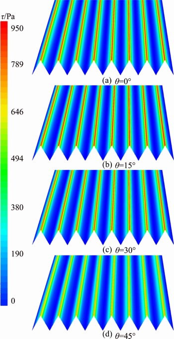
Fig. 7 Contour of wall shear stress in different flow directions
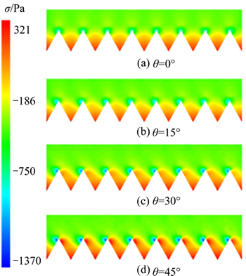
Fig. 8 Contour of pressure stress in different flow directions
4.3 Analysis of flow field velocity
Figure 9 shows a velocity contour and vector of the oblique riblets surface at the Lx=0 section. Figure 9 shows that the velocity gradient of oblique riblets tips changes dramatically. When ��=0��, there is no obvious disturbance inside the riblets. With the increase of ��, there are new vortices appearing in the riblets. And the direction of vortices rotation is along with the flow direction. The vortices intensity gradually increases. The characteristic of travelling wave is gradually formed [22]. The vortices existence keeps the free stream away from the wall and plays the role of lubrication; new vortices reduce wall shear stress and gradually weaken streamwise vortices intensity. Moreover, new vortices suppress the ability that the streamwise vortices rally the low-speed streaks at the spanwise. In other words, burst places will decrease and unsteady flow will diminish. The viscosity resistance decreases due to the existence of new vortices. But pressure resistance increases with the increase of ��.
Figure 10 shows a velocity contour and vector whose section is perpendicular to the flow direction of U (namely spanwise velocity v of oblique riblets).Figure 10 shows that, when ��=0��, the maximum velocity region is near the riblets tips. The secondary vortex structure can be obviously observed in the velocity vector. Due to the existence of the riblets structure, the characteristic of the flow field has been changed, namely the interaction between riblets tips and flow field. The tiny secondary vortex appears near the riblets tips and its direction of rotation differs from streamwise vortices. The secondary vortex shows severe convective motion near the riblets tips [23, 24]. The secondary vortex limits the fluid disturbance at the riblets valleys. So, the low speed, quiet fluid is kept in the riblets valleys. But the interaction between the secondary vortex and the riblets tips causes the increase of velocity gradient above the riblets tips. The secondary vortex changes wall turbulence structure. It diminishes the intensity of streamwise vortices associated with low-speed streaks. Furthermore, it suppresses the diffusion of the streamwise vortices in the spanwise and avoids the spanwise vortices to create severe rising and sweep directly with the riblets surface. In the meantime, the secondary vortex reduces momentum transfer and the turbulence kinetic energy in the riblets surface. Therefore, the friction resistance decreases between the fluid and the wall.
Figure 10 shows that, with the increase of ��, the secondary vortex will gradually disappear; the maximum velocity regions move towards the middle position of the riblets; fluid flow in the spanwise becomes severe and damages the low speed, quiet fluid in the riblets. During the disappearance of the secondary vortex, the new vortices are created and strengthened inside the riblets. What��s more, the vortices play a dominant role on decreasing viscosity resistance. When ��=15��, the new vortices act on the oblique riblets surface and make the decrease of viscosity resistance in some extent; meanwhile, as inclination angle is small, pressure resistance doesn��t increase rapidly. Finally, the total resistance of oblique riblets surface decreases in a certain degree. Therefore, when U=15 m/s, ��=15��, oblique riblets can achieve a better drag reduction effect.
5 Conclusions
1) The change of inclination angle shows a large influence on resistance of oblique riblets. Specially, with increase of inclination angle, pressure resistance increases rapidly, and viscous resistance presents a decreasing trend on oblique riblets surface. Besides, the maximum oblique riblets surface resistance is less than the maximum smooth wall resistance. When the mean velocity is 10 m/s, the drag reduction rate reduces while the inclination angle rises. Under the other rest of velocity, drag reduction rate increases at first then decreases with the increase of the inclination angle. Under each velocity, the maximum drag reduction rate shows an increasing trend; when the inclination angle is 25��, the mean velocity is 25 m/s, and the maximum drag reduction rate is 7.33%.
2) Wall shear stress concentration is caused by secondary vortex structure near oblique riblets tips. When inclination angle rises, wall shear stress weakens in some extent. As fluid becomes steady at riblets valleys, the shear stress is at a low state. Low pressure regions are at riblets tips and the high pressure regions are at riblets valleys. Additionally, with the change of flow direction, high pressure regions at the riblets valleys extend to the one side of the riblets tips and the low pressure regions at the other side of the riblets tips continue to decrease. It results in the differential pressure nearby oblique riblets tips.
3) The vortices structure inside the oblique riblets surface diminishes intensity of streamwise vortices. What��s more, it causes less burst places, weakening of unsteady flow and decrease of wall shear stress. Finally, the viscous resistance decreases. Secondary vortex structure weakens intensity of streamwise vortices and suppresses the diffusion of the stream-wise vortices in the spanwise. Therefore, spanwise vortices won��t create severe rising and sweep directly with riblets surface. With the increase of inclination angle, the secondary vortex in oblique riblets disappears soon. And the steady fluid field is damaged inside the riblets. New vortices are created and strengthened. After new vortices act on oblique riblets, viscosity resistance is decreases. Meanwhile, as inclination angle is small, leads to the slow increase of pressure resistance. As a consequence, oblique riblets surface equips with a better drag reduction effect.
References
[1] CHEN Hua-wei, RAO Fu-gang, SHANG Xiao-peng, ZHANG De-yuan, HAGIWARA I. Biomimetic drag reduction study on herringbone riblets of bird feather [J]. Journal of Bionic Engineering, 2013, 10(3): 341-349.
[2] BUFFAT M, PENVEN L L, CADIOU A, MONTAGNIER J. DNS of bypass transition in entrance channel flow induced by boundary layer interaction [J]. European Journal of Mechanics-B/Fluids, 2014, 43: 1-13.
[3] WALSH M J. Riblets as a viscous drag reduction technique [J]. AIAA Journal, 1983, 21(4): 485-486.
[4] LEE S J, LIM H C, HAN M, LEE S S. Flow control of circular cylinder with a V-grooved micro-riblet film [J]. Fluid Dynamics Research, 2005, 37(4): 246-266.
[5] LEE S J, CHOI Y S. Decrement of spanwise vortices by a drag-reducing riblet surface [J]. Journal of Turbulence, 2008, 9(23): 1-15.
[6] STENZEL V, WILKE Y, HAGE W. Drag-reducing paints for the reduction of fuel consumption in aviation and shipping [J]. Progress in Organic Coatings, 2011, 70(4): 224-229.
[7] CHAMORRO L P, ARNDT R E A, SOTIROPOULOS F. Drag reduction of large wind turbine blades through riblets: Evaluation of riblet geometry and application strategies [J]. Renewable Energy, 2013, 50: 1095-1105.
[8] NUGROHO B, HUTCHINS N, MONTY J P. Large-scale spanwise periodicity in a turbulent boundary layer induced by highly ordered and directional surface roughness [J]. International Journal of Heat and Fluid Flow, 2013, 41: 90-102.
[9] DEAN B, BHUSHAN B. The effect of riblets in rectangular duct flow [J]. Applied Surface Science, 2012, 258(8): 3936-3947.
[10] PEET Y, SAGAUT P, CHARRON Y. Pressure loss reduction in hydrogen pipelines by surface restructuring [J]. International Journal of Hydrogen Energy, 2009, 34(21): 8964-8973.
[11] STALIO E, NOBILE E. Direct numerical simulation of heat transfer over riblets [J]. International Journal of Heat and Fluid Flow, 2003, 24(3): 356-371.
[12] DEAN B, BHUSHAN B. Shark-skin surfaces for fluid-drag reduction in turbulent flow: A review [J]. Philosophical Transactions of the Royal Society A: Mathematical, Physical and Engineering Sciences, 2010, 368(1929): 4775-4806.
[13] LEE S J, JANG Y G. Control of flow around a NACA 0012 airfoil with a micro-riblet film [J]. Journal of Fluids and Structures, 2005, 20(5): 659-672.
[14] DENKENA B,  J, WANG B. Manufacturing of functional riblet structures by profile grinding [J]. CIRP Journal of Manufacturing Science and Technology, 2010, 3(1): 14-26.
[15] GU Yun-qing, ZHAO Gang, ZHENG Jin-xing, LI Zhao-yuan, LIU Wen-bo, MUHAMMAD F K. Experimental and numerical investigation on drag reduction of non-smooth bionic jet surface [J]. Ocean Engineering, 2014, 81: 50-57.
[16] LIN C H, YEN C H, FERNG Y M. CFD investigating the flow characteristics in a triangular-pitch rod bundle using Reynolds stress turbulence model [J]. Annals of Nuclear Energy, 2014, 65: 357-364.
[17] ESCUE A, CUI J. Comparison of turbulence models in simulating swirling pipe flows [J]. Applied Mathematical Modelling, 2010, 34(10): 2840-2849.
[18] TSUKAHARA T, MOTOZAWA M, TSURUMI D, KAWAGUCHI Y. PIV and DNS analyses of viscoelastic turbulent flows behind a rectangular orifice [J]. International Journal of Heat and Fluid Flow, 2013, 41: 66-79.
[19]  A, SANMIGUEL-ROJAS E,
  C. Drag reduction induced by the addition of a multi-cavity at the base of a bluff body [J]. Journal of Fluids and Structures, 2014, 48: 347-361.
[20] TEZDOGAN T, DEMIREL Y K, KELLETT P, KHORASANCHI M, INCECIK A, TURAN O. Full-scale unsteady RANS CFD simulations of ship behaviour and performance in head seas due to slow steaming [J]. Ocean Engineering, 2015, 97: 186-206.
[21] GU Yun-qing, MOU Jie-gang, DAI Dong-shun, ZHENG Shui-hua, JIANG Lan-fang, WU Deng-hao, REN Yun, LIU Fu-qing. Characteristics on drag reduction of bionic jet surface based on earthworm��s back orifice jet [J]. Acta Physica Sinica, 2015, 64(2): 024701.
[22] TAN H F, KANG J T, WANG C G. Study on grooved wall flow under rarefied condition using the lattice Boltzmann method [J]. International Journal of Mechanical Sciences, 2015, 90: 1-5.
[23] EL-SAMNI O A, CHUN H H, YOON H S. Drag reduction of turbulent flow over thin rectangular riblets [J]. International Journal of Engineering Science, 2007, 45(2-8): 436-454.
[24] ABDULBARI H A, YUNUS R M, ABDURAHMAN N H, CHARLES A. Going against the flow��A review of non-additive means of drag reduction [J]. Journal of Industrial and Engineering Chemistry, 2013, 19(1): 27-36.
(Edited by YANG Hua)
Cite this article as:
GU Yun-qing, FAN Tian-xing, MOU Jie-gang, WU Deng-hao, ZHENG Shui-hua, Evan Wang. Characteristics and mechanism investigation on drag reduction of oblique riblets [J]. Journal of Central South University, 2017, 24(6): 1379-1386.
DOI:https://dx.doi.org/10.1007/s11771-017-3542-5Foundation item: Project(51476144) supported by the National Natural Science Foundation of China; Project(LQ15E050005) supported by the Zhejiang Provincial Natural Science Foundation of China; Project(2017C31025) supported by Zhejiang Province Department Public Welfare Industrial Projects, China; Project (2016M601736) supported by China Postdoctoral Science Foundation; Project (1601028 C) supported by Postdoctoral Research Funding Plan in Jiangsu Province, China
Received date: 2015-09-09; Accepted date: 2017-01-03
Corresponding author: GU Yun-qing, Lecturer, PhD; Tel: +86-571-88320651; E-mail: guyunqing@hrbeu.edu.cn
Abstract: This work primarily focuses on the drag reduction characteristics and mechanism investigation of oblique riblets. First, a calculation model of the oblique riblets surface is established, and Reynolds stress model (RSM) turbulence model is used for numerical simulation of the oblique riblets flow field. Subsequently, the influence of inclination angle between flow direction and arrangement direction of riblets on friction resistance and drag reduction rate is further analyzed. Through the investigation of the distribution of shear stress, pressure stress and velocity in oblique riblets boundary layer, the oblique riblets drag reduction mechanism is finally revealed. Results show that, with increase of velocity and inclination angle, the pressure resistance increases obviously, along with the decreasing of the viscous resistance distinctly. The maximum drag reduction rate of the oblique riblets is 7.33%. Moreover, when the inclination angle increases, the wall shear stress reduces on oblique riblets surface; while differential pressure increases at both sides of oblique riblets tips. In addition, when inclination angle is small, the secondary vortex at oblique riblets tips will disappear soon. New vortices will be formed inside the oblique riblets and cause the decrease of viscosity resistance. Thus, oblique riblets show a better drag reduction effect and have an effective control on boundary layer.
