
J. Cent. South Univ. (2016) 23: 77-85
DOI: 10.1007/s11771-016-3051-y

Integrity of grinding face-gear with worm wheel
TANG Jin-yuan(�ƽ�Ԫ), CUI Wei(��ΰ), ZHOU Heng(�ܺ�), YIN Feng(����)
State Key Laboratory of High Performance Complex Manufacturing (Central South University),Changsha 410083, China
 Central South University Press and Springer-Verlag Berlin Heidelberg 2016
Abstract:
Aiming at the issue of the grinding integrity of face-gear with worm wheel, the envelope mathematical model of shaper, worm wheel and face-gear is established based on theories of differential geometry and gear mesh. The judgment of completely grinding the face-gear with the avoidance of singularities is established, and the mathematical expression to show the reason why singularities appear is derived, through the research on the surface contact area and singularity rules of the worm thread surface. The disadvantage of current face-gear grinding method that only part of the working surface of the face-gear can be covered is analyzed and the influence of coefficient of judgment is studied through changing the design parameters.
Key words:
face-gear; surface contact area; singularity of worm; integrity of tooth surface��
1 Introduction
Face-gear is a new type of gear driving with the traits that cylindrical gears meshing with bevel gears, high compact structure, increased gear ratio and smoother transmission [1]. In recent years, the academic and engineering circles have paid high attention to the drive because of its successful application in Apache attack helicopter transmissions by the Northstar Aerospace Company. The research conducted by HEATH et al [2] shows that it is very meaningful to use face-gear for torque split in helicopter transmissions.
As the method and technology of face-gear finish machining is a major issue for face-gear manufacturing, it is an efficient and high precise way to generate face-gear by a grinding worm wheel. Similar to the undercutting of cylindrical gear manufacturing process, the worm thread surface has to be designed as a regular one without singular points according to the surface envelope principle, since the worm thread surface with singular points cannot generate the right tooth surface of face-gear. When there are no singular points on the worm thread surface, the worm wheel width is called effective width of the worm. In some working conditions, the worm within the effective width cannot cover the whole working surface of the face-gear, that is, only part of the working surface of the face-gear is covered. Hence, the grinding integrity of face-gear with worm wheel is involved.
LITVIN et al [1-3] defined the basic theoretical study of face-gear. The apparatus for precision grinding face-gear by a worm tool was developed by LITVIN et al [4]. For grinding face-gear by a worm wheel, LITVIN et al [5] studied the principle of worm surface generation and singularities of the worm thread surface, funded by projects of NASA. What��s more, LITVIN et al [6-10] have researched some different types of geometries of face-gear drives. In order to grind face-gear with a worm wheel, a multi-axis grinding machine to manufacture face-gear was presented by BEEL et al [11]. A method for precision grinding of conical face-gear was proposed by TAN [12]. GAO et al [13], WANG et al [14], and ZHAO et al [15], studied the principle of singularities, the dressing method of worm wheel and the theory error of cutting face-gear with a spherical hob, respectively. In view of the complicatedness of the process of grinding face-gear with a worm wheel, in which special equipment is needed, TANG et al [16] proposed a progressive grinding method for profile modified spur face-gear based on disk wheel, of which the disadvantage is that the efficiency is very low. The documents that we have retrieved so far indicate that no adequate attention has been paid to the issue that the worm may be unable to cover the whole working surface of the face-gear because of singularities, as no relevant literature has been published.
In this work, the envelope mathematical model of shaper, worm wheel and face-gear is established in a unified coordinate system based on theories of differential geometry and gear meshing. The surface contact area between the shaper and the face-gear, and the mathematical expression which shows the reason why singularities appear are derived. The fact that the worm wheel cannot cover the whole working surface of the face-gear has been proved theoretically by the expression derived. The judgment of completely grinding the working surface of the face-gear is established. The rule how designs parameters of the face-gear and geometric parameters of the worm affect the grinding integrity is studied. The research provides the basic theoretical preparation for studying the process of grinding face-gear with a worm wheel.
2 Face-gear generation
According to the principle of face-gear manufacturing process, the worm, the shaper and the face-gear are meshing with each other, and there is a virtual internal meshing relationship between the shaper and the worm. Therefore, with the shaper as a medium in this work, the relationship of the rotation angles of the shaper when generating the worm and the face-gear as well as the grinding integrity of manufacturing the face-gear with the worm is studied in an unified coordinate system. The standard involute profile is used to generate the profile of the face-gear and the worm.
2.1 Geometry of shaper
Figure 1 shows profiles of the shaper and their coordinates. Moveable coordinate systems Os are rigidly connected to the shaper. Axis zs, which is the axis of rotation of the shaper, is orthogonal to plane Oxy. Static coordinate system Os0 coincides with the initial position of the shaper. The profiles ��1 and ��2 are symmetrical about the plane Oyz.

Fig. 1 Profiles of shaper and coordinates
Shaper surface ��1 is determined in coordinate system Os by the following equation:
 (1)
(1)
here, the angle between y axis and the line from the starting point of the involute to the origin of the coordinates is ��s0, which is determined by Eq. (2), in which ��s is the pressure angle of the shaper and Ns is the number of teeth of the shaper.
 (2)
(2)
2.2 Generation of tooth surface of face-gear
According to the principle of slotting face-gear with a shaper, the fixed coordinate systems Os0 and O20 applied for illustration of installment of the face-gear with respect to the shaper are established when the shaft angle is 90�� (Fig. 2). The moveable coordinate systems Os and O2 are rigidly connected to the shaper and the face-gear. ��s and ��2, which are the angles of rotation of the shaper and the face-gear respectively, satisfy ��2=Ns��s/N2 (N2 is the number of teeth of the face-gear).
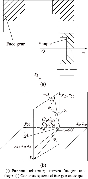
Fig. 2 Coordinate systems applied for generation of face-gear surface:
Hence, the face-gear surface ��2 is determined in coordinate system O2 (Fig. 2) by
 (3)
(3)
where the matrix M2,s describes the coordinate transformation from Os to O2;  is the relative (sliding) velocity.
By solving the meshing equation f2s(��s, us, ��s)=0, we can represent the surface of the face-gear by a vector function:
 (4)
(4)
3 Analysis of instantaneous contact lines between shaper and face-gear
3.1 Calculation of instantaneous contact lines
According to the theory that the shaper and the face-gear mesh with each other, it is known that the shaper surface ��s is in line contact with the face-gear surface ��2 in every moment.
With the use of Eq. (4), a contact line can be obtained by making ��s fixed and ��s discrete. Hence, the contact lines of the face-gear surface ��2 can be determined by
 (5)
(5)
where  is the fixed angle of rotation of the shaper. Consequently, the contact lines on the surface of the face-gear can be obtained by choosing different values for [18].
Table 1 Design parameters of face-gear drive
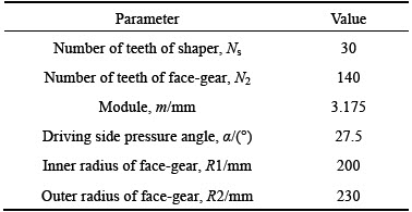
Taking the design parameters listed in Table 1 for example, the contact lines on the surface of the face-gear can be obtained by solving Eq.(5). Figure 3 is obtained in considering of ��min�ܦȡܦ�max. Figures 3(a) and (b) show that the contact line is a symmetric distribution in the tooth surface of the face-gear.
3.2 Limit angle when meshing between shaper and face-gear
As shown in Fig. 3(b), the rotation of the shaper is in the range of -34.14�� to 8.59�� during the meshing process with the face-gear. It can be known that the maximum and minimum values of ��s occur when the contact line reaches points B and A respectively (see Fig. 4). As can be seen from Fig. 4, points A and B are located at the top and bottom of the working tooth surface of the face-gear respectively.
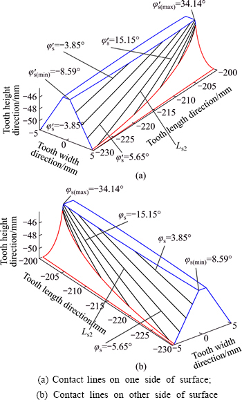
Fig. 3 Contact lines on surface of face-gear:
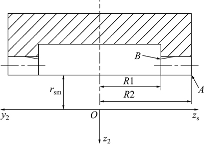
Fig. 4 Illustration of positions of points A and B
Using Eqs. (1) and (4), and assuming that:
 (6)
(6)
 (7)
(7)
The maximum value of ��s can be obtained by
 (8)
(8)
The minimum value of ��s can be obtained by
 (9)
(9)
Because of the symmetric distribution of the contact lines, we can obtain the value of  and
and 
4 Principle of face-gear grinding based on worm wheel
In this section, the method of grinding face-gear based on the application of a worm wheel will be presented and the grinding process will be based on the simulation of meshing the face gear with the shaper. The principle of grinding is shown in Fig. 5. During the grinding process, the worm wheel rotates around its own axis zw while the face-gear rotates around its own axis z2. In addition, in order to cut the tooth surface of the face-gear completely, the worm wheel also needs to traverse along the entire face width of the face-gear.
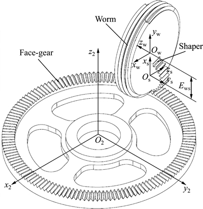
Fig. 5 Illustration of simultaneous meshing of shaper, worm, and face-gear
4.1 Generation of worm surface
According to the principle that there is a virtual internal meshing relationship between the shaper and the worm, the worm surface ��w can be calculated as the envelope of the families of the shaper surface ��s, as Fig. 5 shows. The movable coordinate systems Os and Ow are rigidly connected to the shaper and the worm, respectively (see Fig. 6). At the same time, the coordinate systems Os0 and Ow0 are fixed (see Fig. 6).
In Fig. 6, Ews is the shortest distance between the axis zw and xs. The crossing angle between axes of the shaper and the worm is ��w=arcsin[(rps/Ns(rps+Ews))] [5]. The angles of rotation of the shaper, ��s, and the worm, ��w, are related as ��w=Ns��s/Nw. And rps is the radius of the pitch circle of the shaper. Nw is the number of threads of the worm, and one thread of the worm is used usually. Therefore, Nw is equal to 1 in this work by default.
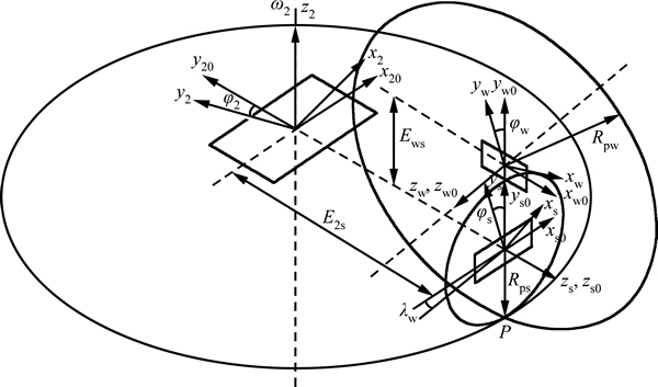
Fig. 6 Coordinate systems applied for generation of worm surface
The position vector rw of the face-gear surface can be expressed by Eq. (10) in the coordinate system Ow as:
 (10)
(10)
where the matrix Mws describes the coordinate transformation from Os to Ow;  is the relative (sliding) velocity.
By solving equation fws(��s, ��s, us)=0, the surface of the worm can be represented by a vector function as
 (11)
(11)
The normal to the worm is represented in coordinate system Ow as
 (12)
(12)
where the matrix Lws(��s) is the 3��3 order sub matrix of the matrix Mws.
4.2 Size of worm limited by singularities
Since the worm surface ��w is not necessarily a regular surface, it may have singular points which will affect the processing precision and performance of the worm. Therefore, it is a necessity to prevent the worm tooth surface singularities from occurring. It is proved that surface singularity will occur if the following equation is satisfied as [13]
 (13)
(13)
where  is the velocity of a point that moves over the tool surface ��s and
  is the relative sliding velocity in the meshing of surfaces ��s and ��w.
Application of Eq.(1) and the differentiated equation fws(��s, ��s, us)=0 enables us to obtain a system of four linear equations with two unknowns.
 (14)
(14)
 (15)
(15)
The system has a definite solution for the unknowns if the matrix A has the rank r=2. Using Eqs. (1), (10) and (15), the lines on ��s that generate singular points on surface ��w are determined by
 (16)
(16)
The design parameters of the worm considered for this example are represented in Table 2. The results represented in Fig. 7 are obtained considering ��min�ܦȡܦ�max and Eq. (16). As can be seen from Fig. 7, there are two singular restrictive lines. Due to the existence of the restrictive lines, the rotation of the shaper is limited in the range of -18.3�� to 130.4�� when the worm is generated. While what Fig. 7 shows is just one side of the tooth surface of the face-gear, it is easy for us to obtain the rotation rang of the shaper when the other side of the tooth surface of the face-gear is generated because of the symmetrical characteristic [5], namely, the range from 18.3�� to -130.4��. Taking both sides of the tooth surface into consideration, the final rang of rotation of the shaper is -18.3��� ��18.3��.
Table 2 Design parameters of worm
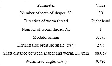
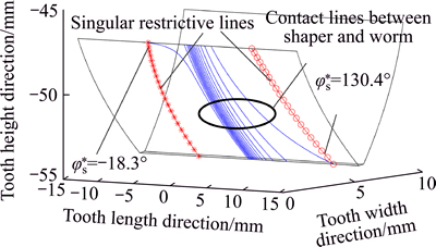
Fig. 7 Illustration of regular point L of shaper that generates worm singularities
According to the final rang of rotation of the shaper  the 3-D model of the worm is established in the environment of CATIA V5 (see Fig. 8(a)). Figure 8(b) shows both sides of worm tooth surface in the range of rotation of [-18.3��, 30��] and [-30��, 18.3��] because of the image size in the environment of MATLAB.
5 Analysis of grinding integrity of face-gear when grinded by worm
The shaper surface ��s is in line contact with both the worm surface ��w and the face-gear tooth surface ��2. The line of tangency between ��s and ��w is described by the name of Lsw and the line of tangency between ��s and ��2 by the name of Ls2, respectively. Lines Lsw and Ls2, instead of coinciding with each other, intersect at any position of meshing, as shown in Fig. 9 where lines Ls2 and Lsw intersect with each other at a meshing position. The point of intersection of Ls2 and Lsw corresponds tothe point of tangency of surfaces ��2 and ��w. This means that, in order to finish the grinding process of ��2 by the worm surface ��w, it must be based on a two-parameter enveloping process wherein there are two independent sets of parameters which are the angles of rotation of the worm and the face-gear (��w, ��2) and a translational motion lw of the worm.
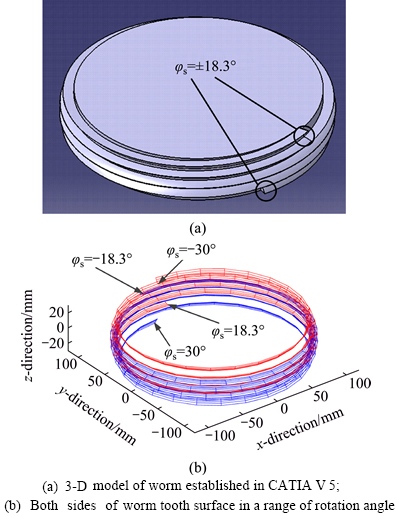
Fig. 8 Illustration of worm limited by singularities:
Parameters ��w and ��2 are the angles of rotation of the worm and the face-gear related as ��2=Nw��w/N2, where N2 is the number of teeth of the face-gear. Parameter lw of the translational motion is collinear to the axis of the shaper.
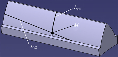
Fig. 9 Illustration of lines Ls2 and Lsw intersecting with each other at a point
As shown in Fig. 6, the coordinate systems Ow and O2 are rigidly connected to the worm and the face-gear, respectively; the coordinate systems Ow0 and O20 are fixed coordinate systems, and Ews is the shortest distance between the axis zw and xs. Then, the position vector of the face-gear surface is determined as
 (17)
(17)
Where the matrix M2w describes the coordinate transformation from Ow to O2. The equations  and
and represent the two equations of meshing of the two-parameter enveloping process of generation.
5.1 Calculation of contact points between face-gear and worm
In order to get the whole working surface of the face-gear covered, the worm and the face-gear should rotate around their own axes, and the worm wheel also needs to traverse along the entire face width of the face-gear at the same time.
Using Eq. (17), the contact points on surface ��2 can be obtained by the following steps:
Step 1: giving ��s a set of values and making lw a constant value.
Step 2: giving lw another constant value and repeating Step 1.
When all the steps above are finished, the contact points between the surface of the worm and that of the face-gear can be obtained. Using Eqs. (8), (9) and (17) and considering ��w=Ns��s/Nw at the point of intersection (see Fig. 9), the values for ��w of the worm to completely grind the working surface of the face-gear are determined by (Fig. 10)

 (18)
(18)
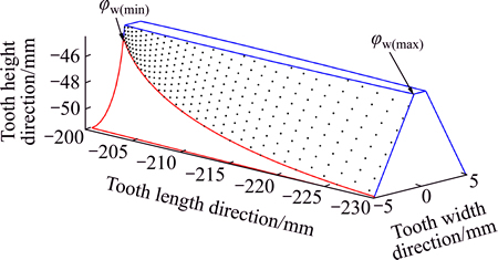
Fig. 10 Illustration of values for ��w of worm to completely grind face-gear
5.2 Judgment of completely grinding face-gear by worm
5.2.1 Calculation of coefficient k of judgment
The worm thread surface has to be designed as a regular one. Using Eq. (16) and considering ��w=Ns��s/Nw, the values for ��w of the worm to avoid singularity points (see Fig. 11) can be obtained and they are determined by
 (19)
(19)
In order to completely grind the face-gear by the worm wheel with the avoidance of singularities, the values for ��w of the worm to avoid singularity points determined by Eq. (19) should include the values for ��w of the worm to completely grind the face-gear determined by Eq. (18). Therefore, the coefficient k of the judgment is determined by
 (20)
(20)
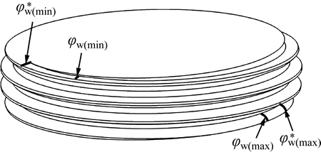
Fig. 11 Illustration of coefficient of judgment k>1
5.2.2 Numerical example
The design parameters of the face-gear drive considered for this example are described in Table 3. The results represented in Fig. 12 are obtained considering Eq. (17), ��min�ܦȡܦ�max and  Figure 12 shows that the instantaneous contact points of ��w and ��2 do not cover the whole working surface of the face-gear. This means that in the grinding process, the worm wheel cannot completely grind the entire working surface of the face-gear.
5.2.3 Factors affecting surface integrity of face-gear grinding by worm
Using Eq. (10), Eq. (21) can be obtained after derivations. As can be seen from Eq. (21), the value of us will increase sharply to cross the singular boundary line when the denominator of the equation is close to 0. If the solution of us (Eq. (21)) is between the two singular boundary lines when the value of ��s is in the range of [-34.14��, 8.59��], then the whole working surface of the face-gear can be covered by the worm (see Fig. 7).
 (21)
(21)
The factors that affect the surface integrity of face-gear grinding by the worm are ��w, Ews, Ns, rb and��s+��s0+��s. However, when the design parameters of a face-gear drive are given with the worm for grinding, the only parameter that can be changed is Ews. Taking the parameters in Table 3 as example, where the range of ��s+��s0 is [19.43��, 40.85��] is, and the range of ��s is [-34.14��, 8.59��] (see Fig. 7), the value of ��s+��s0+��s will be close to 0, leading the value of us to increase sharply to cross the singular boundary line. Consequently, no matter how the value of Ews is changed, the value of us will be out of the two singular boundary lines, so that only part of the working surface of the face-gear can be covered by the worm wheel.
Table 3 Design parameters of face-gear grinded by worm
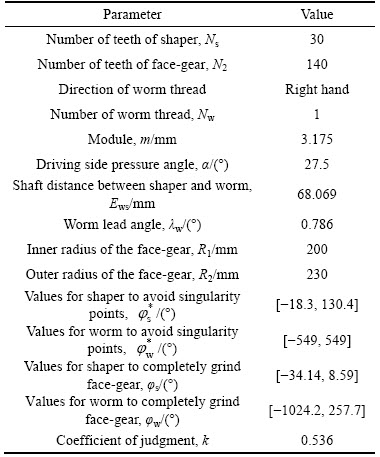
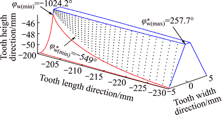
Fig. 12 Illustration of surface ��2 generated by surface ��w when k<1
Then a conclusion can be reached that there will be such a phenomenon that no matter how the parameters of the worm tool are changed, the working surface of the face-gear cannot be covered completely under some design parameters of the face-gear. For the sake of improving the surface integrity of face-gear grinding by the worm, the way the design parameters of the face-gear affect the coefficient k of the judgment is studied based on the parameters represented in Table 3. Figure 13, which shows how the changes of one of the parameters of the face-gear drive may affect the value of k reveals the following information:
1) The module and driving side pressure angle exert the most remarkable influence on the value of k.
2) Only a minor area of the face-gear can be grinded completely by a worm tool.
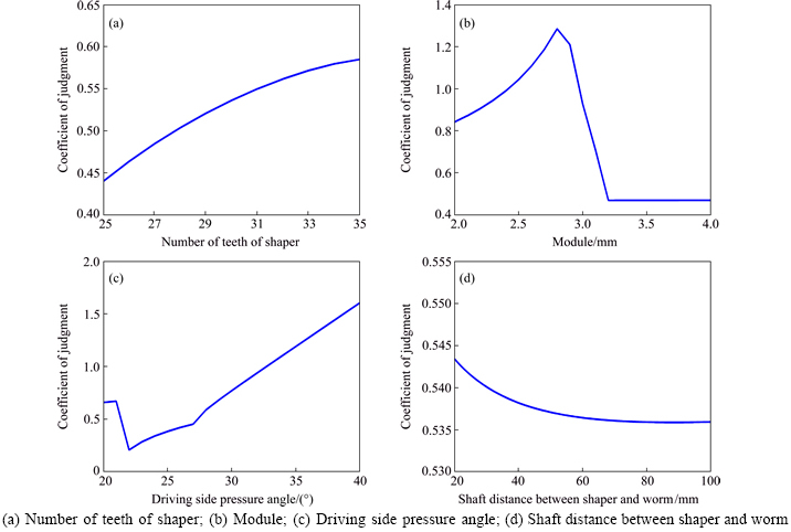
Fig. 13 Effects of different parameters on value of k:
6 Conclusions
1) The value range of ��w of the worm to completely grind the face-gear is derived through the research on the surface contact lines between face-gear-shaper and worm-shaper.
2) The value range of the worm  to avoid singularity points is derived through the research on the principle of singularity.
3) The judgment of completely grinding the face-gear by a worm is established, that is, the coefficient k is equal to or greater than 1.
4) Most areas of the face-gear cannot be ground completely by a worm, and the module and driving side pressure angle exert the most remarkable influence on the grinding integrity of the face-gear.
References
[1] LITVIN F L. Application of face gear drives in helicopter transmissions [J]. Transaction of the ASME, Journal of Mechanical Design, 1994, 116: 672-676.
[2] HEATH G F, FILLER R R, TAN J. Development of face gear technology for industrial and aerospace power transmission [R]. NASA Contactor Report, 211320, 2002.
[3] LITVIN F L, HSIAO C L. Computerized simulation of generation of internal involute gears and their assembly [J]. Transactions of ASME, Journal of Mechanical Design, 1994, 116: 683-689.
[4] LITVIN F L, CHEN Y D, HEATH G F, CHEN N. Apparatus and method for precision grinding face gear: US, 6146253 [P]. 2000.
[5] LITVIN F L, FUENTES A, ZANZI C, PONTIGGIA M, HANDSCHUH R F. Face gear drive with spur involute pinion: geometry, generation by a worm, stress analysis [J]. Computer Method in Applied Mechanics and Engineering, 2002, 191(25/26): 2785-2813.
[6] LITVIN F L, EGELJA A, TAN J, HEATH G.. Computerized design, generation and simulation of meshing of orthogonal offset face gear drive with a spur involute with localized bearing contact [J]. Mechanism and Machine Theory, 1998, 22(1/2): 87-112.
[7] LITVIN F L, NAVA A, FAN Q, FUENTES A. New geometry of face worm gear drives with conical and cylindrical worms: generation, simulation of meshing, and stress analysis [J]. Computer Methods in Applied Mechanics and Engineering, 2002, 191: 3035-3054.
[8] LITVIN F L. Design, generation and stress analysis of face-gear drive with helical pinion [J]. Computer Methods in Applied Mechanics and engineering, 2005, 194: 3870-3901.
[9] LITVIN F L, IGNACIO G P, KENJI Y, LITVIN F L, GONZALEZ-PEREZ I, YUKISHIMA K, FUENTES A, HAYASAKA K. Design, simulation of meshing, and contact stresses for an improved worm gear drive [J]. Mechanism and Machine Theory, 2007(42): 940-959.
[10] LITVIN F L, GONZALEZ-PEREZ I, FUENTES A, HAYASAKA K. Design and investigation of gear drives with non-circular gears applied for speed variation and generation of functions [J]. Computer Methods in Applied Mechanics and Engineering, 2008, 197: 3783-3802.
[11] BEEL K, FISHER D, RUSSELL A, FOLPRECHT G. Face gear manufacturing method and apparatus: US, 6390894, B1 [P]. 2002.
[12] TAN J. Tool and method for precision grinding of conical face gear that meshes with a conical involute pinion: US, 6602115,B2[ P]. 2003.
[13] GAO Jin-zhong, ZHU Ru-peng, LI Zheng-min-qing. Research on singularities of base worm thread surface for hobbing or grinding face gear [J]. Journal of Aerospace Power, 2011, 26(10): 2394-2400. (in Chinese)
[14] WANG Yan-zhong, WU Can-hui, GE Xu-yang, ZHANG Li. Basal worm-designing method of face-gear hob [J]. Journal of Beijing University of Aeronautics and Astronautics, 2009, 35(2): 166-169. (in Chinese)
[15] ZHAO Ning, GUO Hui, FANG Zong-de, SHEN Yun-bo. Theory error of cutting face gears with sphericity hob [J]. Journal of Aerospace Power, 2009, 24(3): 677-682. (in Chinese)
[16] TANG Jin-yuan, YIN Feng, CHEN Xing-ming. The principle of profile modified face-gear grinding based on disk wheel [J]. Mechanism and Machine Theory, 2013, 70: 1-15.
[17] LITVIN F L, GUO Kai, YE Ling-yun, FAN Lin. Gear geometry and applied theory [M]. Shanghai: Science and Technology Press, 2008. (in Chinese)
(Edited by YANG Hua)
Foundation item: Projects(51275530, 51535012) supported by the National Natural Science Foundation of China; Project(2011CB706800) supported by the National Basic Research Program of China
Received date: 2014-11-24; Accepted date: 2015-03-04
Corresponding author: TANG Jin-yuan, Professor; Tel: +86-731-88877746; E-mail: jytangcsu312@163.com
Abstract: Aiming at the issue of the grinding integrity of face-gear with worm wheel, the envelope mathematical model of shaper, worm wheel and face-gear is established based on theories of differential geometry and gear mesh. The judgment of completely grinding the face-gear with the avoidance of singularities is established, and the mathematical expression to show the reason why singularities appear is derived, through the research on the surface contact area and singularity rules of the worm thread surface. The disadvantage of current face-gear grinding method that only part of the working surface of the face-gear can be covered is analyzed and the influence of coefficient of judgment is studied through changing the design parameters.
