
Trans. Nonferrous Met. Soc. China 29(2019) 112-122
Bulging in incremental sheet forming of cold bonded multi-layered Cu clad sheet: Influence of forming conditions and bending
Khalid A. AL-GHAMD1, G. HUSSAIN2
1. Department of Industrial Engineering, King Abdulaziz University, Jeddah, Saudi Arabia;
2. Faculty of Mechanical Engineering, GIK Institute of Engineering Sciences & Technology, Topi, 23460, KP, Pakistan
Received 22 February 2018; accepted 16 May 2018
Abstract:
Bulge is a defect that causes geometrical inaccuracy and premature failure in the innovative incremental sheet forming (ISF) process. This study has two-fold objectives: (1) knowing the bulging behavior of a Cu clad tri-layered steel sheet as a function of forming conditions, and (2) analyzing the bending effect on bulging in an attempt to identify the associated mechanism. A series of ISF tests and bending analysis are performed to realize these objectives. From the cause-effect analysis, it is found that bulge formation in the layered sheet is sensitive to forming conditions in a way that bulging can be minimized utilizing annealed material and performing ISF with larger tool diameter and step size. The bending under tension analysis reveals that the formation of bulge is an outgrowth of bending moment that the forming tool applies on the sheet during ISF. Furthermore, the magnitude of bending moment depending upon the forming conditions varies from 0.046 to 10.24 N��m/m and causes a corresponding change in the mean bulge height from 0.07 to 0.91 mm. The bending moment governs bulging in layered sheet through a linear law. These findings lead to a conclusion that the bulge defect can be overcome by controlling the bending moment and the formula proposed can be helpful in this regards.
Key words:
incremental forming; clad sheet; bulge; bending moment; forming conditions;
1 Introduction
Incremental sheet forming (ISF) is a relatively new process in the domain of sheet metal forming. By definition, this is a process whereby a flat sheet is transformed into a desired three-dimensional shape without the application of dedicated dies and punches (Fig. 1(a)). Compared with the conventional incremental forming processes, such as metal spinning and backward bulging, the ISF process is more flexible in respect of shape complexity and tooling [1]. Water jet forming (WJF) is a novel alternative of ISF; however, this process demands higher capital investment [2-4]. Therefore, to date, ISF is thought as a promising and economical option amongst various incremental forming methods.
At present, due to slow forming speed, ISF is feasible to produce small batches. However, with advancement in the technology, the process has potential to be employed for large-scale production. High speed ISF is a good piece of work in this context [5]. ISF is now a well-established process and its further details can be reviewed in the published literature [6-9].
Similar to traditional metal forming processes, ISF also suffers from defects such as bulge, wall and corner-fold [10]. As shown in Fig. 1(a), bulge is a defect that develops in the bottom of a part. This defect causes geometrical errors and may lead to premature sheet failure, thus adversely affecting the overall process performance. Limited efforts have been spent to control this defect. In this regards, HUSSAIN et al [10,11] proposed to employ optimum process conditions as one of the possible solutions. AL-GHAMDI and HUSSAIN [12] suggested to use pre-strained sheet. ISIDORE et al [13] proposed to utilize flat-end tool to minimize bulging. Although these studies have significant contribution to bulging in ISF, insights into the bulging of layered clad sheet(s) have not been presented in the literature.
The clad sheet metal is a class of composites fabricated to satisfy special needs, e.g., high fracture toughness, improved conductivity and better wear resistance. The clad is composed of multiple layers of different materials, often bonded through cold rolling process. A number of studies on conventional forming of clad metals [14-17] have reported that this class of materials exhibits essentially different forming behaviors relative to monolithic sheets. Therefore, the knowledge reported on bulging of monolithic sheets in ISF might not be directly applicable to control bulging in clad sheets. Keeping in view increasing applications of clad metals in industry and potential applications of ISF as an innovative forming method, it is necessary to determine bulging response of clad metals to ISF processing.
Moreover, most of the bulge-related studies in ISF have been experimental in nature. In order to methodically control this defect, there is a need to identify the related cause or mechanism. The deformation in ISF is jointly achieved by bending, stretching and shearing [18]. As shown in Fig. 1(a), the moment due to bending load applied by the forming tool tends to cause curvature change in its surrounding that further develops into bulge in a series of incremental steps. Bulging (say height of bulge) is likely to vary as the applied moment varies. A systematic bending analysis is required to acquire insights into this point in order to adequately understand and control bulging.
The present study addresses the above-mentioned gaps. The tri-layered Cu/steel clad sheet is employed as the experimental material. To begin with, the bulging response of layered sheet is examined subjecting the sheet to various ISF conditions. This yields a detailed cause-effect analysis providing insights into bulging behavior of clad sheet. In the second step, bending analysis is performed to determine the moment and its associated effect on bulging. Correlation between the bending moment and bulge height is established to reveal how bending affects the formation of bulge in ISF.
2 Experimental
The experimental material employed in the present work was Cu clad steel sheet. The sheet was comprised of three layers stacked as Cu/steel/Cu, as shown in the optical micrograph in Fig. 2. The Cu layers were composed of 99.9% pure Cu, and the steel layer was composed of DC04 steel (0.15% C and 99.85% Fe). The layers were bonded through cold rolling by applying 50% thickness reduction. After rolling, the overall thickness of layers was about 1 mm (where the steel layer was about 0.9 mm thick). The clad sheet was annealed over a range of temperatures, as given in Table 1, in order to minimize the rolling stresses. To determine the mechanical properties, tensile samples following the ASTM E8 standard were cut in the rolling and transverse directions of sheet. The tension tests were conducted at the crosshead speed of 2 mm/min utilizing the Instron machine. Figure 2 presents the representative stress-strain curves against two extreme annealing conditions (i.e., 25 ��C and 700 ��C). A series of such plots were drawn for the range of temperatures and the important mechanical properties were determined in the rolling and transverse directions. The mean values of these properties, namely yield stress (��y), hardening exponent (n) and strength coefficient (K) are given in Table 1. The values of n and K were determined by plotting the true stress-strain data on the logarithmic scale as reported in MARCINIAK et al [19].

Fig. 1 Schematic of bending under tension in ISF
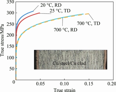
Fig. 2 True stress-true strain curves of Cu/steel/Cu clad sheet
Table 1 Mechanical properties of Cu/steel/Cu clad sheet

The bulging response of Cu/steel clad sheet to ISF processing was studied by varying forming conditions. In order to adequately incorporate the effect of forming conditions, design of experiments (DoE) approach was employed, as DoE contrary to ad-hoc approach (vary one condition keeping the others fixed) considers the combined effects besides individual effects. The test plan was formulated through response surface design, because this design requires less runs and it plots a response in 3D space thus allowing deeper cause-effect analysis. The design of the following mathematical form was employed:
Y=f (X1, X2, X3,��, Xn)+E (1)
where Xi is the variable (i.e., forming condition), E is the error due to noise and Y is the response (i.e., bulge height).
A statistical package Design Expert DX-10 was utilized for design and analysis. Five conditions namely tool diameter (d), wall angle (��), spindle rotation (��), feed rate (f), temperature (T) and step size (p), as defined in Fig. 1(a), were varied over wide ranges (Table 2). The design space included the following points: model points of 28, lack-of-fit points of 5, replicates of 4, and additional center points of 1. These points summed to 38 runs whereby each of the forming conditions had five levels as detailed in Table 2.
The frustum of pyramid was formed as the test geometry (inset in Fig. 1(a)). To produce this geometry, blank of 140 mm �� 140 mm �� 1 mm in size was clamped on a rig. The forming was performed utilizing a steel tool, whose motion was controlled through a three-axis CNC milling machine (Maker: Sky Corporation). After having formed, the specimens were cut into two halves utilizing a wire-cut machine and a depth gauge was used to measure the height of bulge on at least five points in an accuracy of ��0.01 mm.
3 Experimental results
Figure 3 exhibits the bulge profiles of three representative specimens. As can be seen, the bulge height gradually increases from the periphery towards the center of specimen and achieves the maximum value at the center. Based on this trend, two measures were defined to characterize bulging in the clad sheet, namely maximum bulge height (Hmax) and root mean bulge height (Hm) defined as below:
 (2)
(2)
where Hi is the bulge height measured at the ith point, and l is the number of points.
Table 2 lists the bulge height recorded for the Cu/steel clad sheet in 38 tests. As can be seen, in respect of Hmax, test 4 experiences the least bulging while test 36 endures the maximum bulging. The value of Hmax varies from 0.1 to 1.44 mm.
In order to know the significant parameters affecting bulging in the clad sheet, analysis of variance (ANOVA) was performed on the bulge height. The quadratic model was chosen as the fit model. The ANOVA results are presented in Table 3. The terms with p*��0.05 are shown to be significant. It is observed from Table 3 that the parameters interact with each other (e.g., d�� and dp in the case of Hm). This means that the nature of influence of one parameter depends on that of the interacting parameter.
Table 2 DoE test plan and results
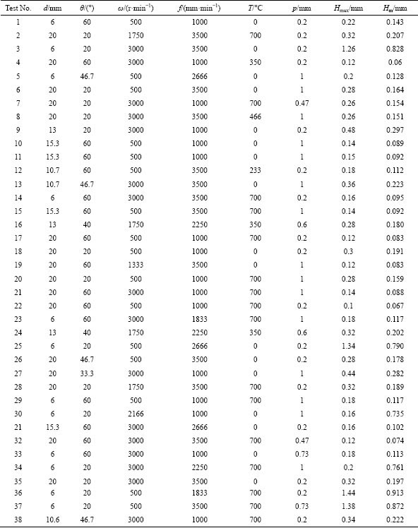

Fig. 3 Bulge profiles for selected Cu/steel/Cu specimens
Figure 4 portrays the influence of forming conditions on the mean bulge height (Hm). Regardless of the interacting parameters, the bulge height sharply increases as the angle increases from 20�� to 35�� and afterwards gradually decreases when the angle increases from 35�� to 60��. This can be observed from a number of response surfaces, i.e., Figs. 4(a, c-e). The bulge height in general reduces with the increase of tool diameter from 6 to 20 mm (Fig. 4(a)). This reduction is sharp when step size is small (0.2 mm). However, when step size is large (1 mm), relatively slight increase is observed in the bulge height (Fig. 4(b)). The height of bulge falls as the rotation increases (from 500 to 3000 r/min) and further this fall is dominant when the angle is low (20��). The bulge contrarily increases when the feed rate increases from 1000 to 3500 mm/min (Fig. 4(d)). Generally, the bulge height decreases as the step size increases from 0.1 to 1 mm. Furthermore, this effect is dominant when the tool diameter and angle are low (i.e., 6 mm and 20��). With the increasing of annealing temperature (from 0 to 700 ��C), the bulge decreases especially when the step size is low (0.2 mm). However, there is a slight increase in the bulge height when the step size is high (1 mm) (Fig. 4(f)). Among all, the effects of feed rate and rotations are comparatively low.
Table 3 Analysis of variance for response surface quadratic model

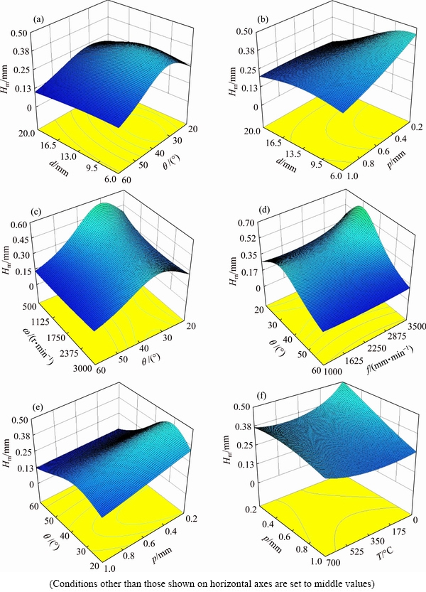
Fig. 4 Effect of parameters on mean bulge height
The response of maximum bulge height (Hmax) to variation in the parameters is observed to be similar to that detailed for the mean bulge height. Therefore, separate details are not reported.
From Fig. 4 and above discussion, it follows that large tool diameter, medium annealing temperature, low rotation, high step size and intermediate feed rate are conducive for minimizing bulging in ISF of Cu/steel clad sheet for a given angle. The feed rate and rotation are relatively less influential; therefore, these parameters can be kept high to enhance the process performance in respect of productivity and formability.
4 Bending analysis
EMMENS and BOOGAARD [20] and FANG et al [18] have reported that the sheet in ISF experiences bending under tension. Therefore, in order to know the role of bending on bulging, the authors performed bending analysis with superimposed tension. To perform this analysis, the authors followed the approach presented in MARCINIAK et al [19].
Note that the forming tool simultaneously applies the tension and bending moment on the unit width of sheet during forming. The resulting bent section and its equilibrium diagram are presented in Fig. 1(a).
Suppose an element of thickness dy and unit width (1) is situated at a distance y from the middle surface. The element experiences the strain ��1 in the applied tension direction. This strain is the sum of stretching strain and bending strain as depicted in Fig. 1(b) and can be determined using the following relation:
 (3)
(3)
where ��a is the strain due to stretching of sheet; ��b is the strain due to bending of sheet.
Consider a simple case of strain hardening in which the true stress-true strain curve is linear near the middle of section and the total stress can be given by
 (4)
(4)
where ��a is the stress due to stretching of sheet; ��b is the stress due to bending of sheet; ��1a is the stretching strain in the middle surface; C is the slope of true ��1-��1 curve at ��1=��1a, i.e., slope of the linear segment of curve near the middle surface of considered section. The stress distribution across the section is shown in Fig. 1(c). As illustrated, the slope C is multiplied with the bending strain to calculate the bending stress below and above the middle surface.
Assuming that the sheet in ISF experiences plane strain deformation (as minor strain in most of the cases remains zero [18]) and strain hardening obeys the power law, C can be determined:
 (5)
(5)
K�� is the strength coefficient in plane strain deformation, related with the constants of uniaxial stretching as follows:
 (6)
(6)
where K is the strength coefficient in uniaxial stretching; n is the strain hardening exponent in uniaxial stretching.
The bending moment M that the element of thickness dy and unit width (1) endures during ISF, is the product of applied tension force F and distance y from the middle surface:
 (7)
(7)
 (8)
(8)
While solving above integral, the stress ��a due to stretching is ignored as it does not affect bending moment.
Considering that the recovery of moment is elastic (i.e., M=��M), the following elastic equation can be employed to determine the change in curvature:
 (9)
(9)
where I is the moment of inertia. For unit width, it can be calculated using the following relation:
 (10)
(10)
��M is the change in bending moment due to unloading; ����1 is the change in stress ��1 due to unloading; E�� is the plane strain elastic modulus.
The Eqs. (8)-(10) can be combined to obtain the change in curvature as follows:
 (11)
(11)
The plane strain elastic modulus E�� is determined by the following relation:
 (12)
(12)
where E is the elastic modulus in uniaxial tension; v is the Poisson ratio.
For more details on the derivations, the reader is referred to MARCINIAK et al [19].
It can be noticed from Eqs. (5)-(8) that the bending moment depends upon the plastic constants (n, K), curvature radius ��0 and plastic strain ��1 applied on the sheet. The values of n and K have been observed to vary with the annealing temperature (T, a variable of current study), as given in Table 1. The value of ��0 can be determined using the tool radius r and thickness t, as illustrated in Fig. 1(b) and given below:
��0=t/2+r (13)
where t0 is fixed but r (i.e., d/2) is a variable in this study. The plastic strain ��1 depends on the forming conditions, specifically wall angle ��, tool radius r and step size p [8]. The other forming conditions namely feed rate f and rotation �� may affect friction at the tool-sheet interface [5]; however, these do not seem to have very significant effect on sheet bending. Therefore, for the sake of simplicity, their influence on the bending moment is ignored at present.
To compute the bending moment, the necessary parameters of Eq. (8) were determined as follows. The plastic constants n and K were determined by plotting the stress/strain data (tension test) on logarithmic scale, as listed in Table 2. Having known these constants, the value of K�� was computed using Eq. (6). The value of slope C was obtained using Eq. (5). The strain ��1a in this equation is the stretching strain applied to the middle surface. Its value was determined making use of the thickness t of formed sheet and the thickness t0 of unformed sheet. The Cosine law [18] offers a reasonable approximation of t; however, it was experimentally measured from parts in order to obtain accurate results.
In order to determine the curvature change ��(1/��) due to unloading, the slope C was obtained as explained before. The plane strain elastic constant E�� was calculated using Eq. (12), while the values of E and �� (elastic constants in uniaxial tension) were kept fixed for the range of annealing temperatures. In fact, low temperature heat treatment does not substantially affect these constants specifically those of low carbon steels [21]. As the present material was mainly composed of low carbon DCO4 steel (90%, volume fraction) and the maximum temperature employed (700 ��C) was below its phase transformation temperature (720 ��C), the E (207 GPa) and �� (0.33) were assumed to remain unaffected by the current heat treatment process. For the reader��s clarity on the calculation procedure, the major parameters for the first six tests (Table 2) are shown in Table 4.
Figure 5 presents the bending moment applied by the forming tool on the unit width of sheet during forming. As can be seen, the moment ranges from 0.046 to 10.24 N��m/m, revealing that the applied moment varies with a variation in the forming conditions. The effect of this moment on the mean bulge height (Hm) is shown in Fig. 6. This is worth seeing that the bulge height increases from 0.07 to 0.91 mm as the bending moment increases from 0.046 to 10.24 N��m/m. It is also to observe from Fig. 7 that bulging increases with the change in curvature (��1/��) due to elastic recovery increasing. These trends endorse that the bending moment plays an important role in the formation of bulge in ISF. The behavior of bulging as a function of moment is governed by the following linear formula:
Hm=0.079M+0.081 (14)
Combined with Eq. (8), the above equation can be re-written as follows:
 (15)
(15)
This is worth noticing from Eq. (15) that the smaller value of slope C and greater value of curvature radius ��0 are conducive in minimizing bulging. The value of C can be reduced by increasing stretching strain and that of ��0 can be increased by employing greater tool radii. The R2 value for the proposed formula is found to be high (i.e., 90%). This means that the formula can be reliably used to predict the bulge height and hence to control bulging without performing hit and trial runs.
Since bending moment depends upon the forming conditions, as mentioned before, and there is a consistent relationship between the moment and bulge height, it can be said that the variation in the bulge height due to variation in the forming conditions shown in Fig. 4 occurs due to corresponding variations in the bending moment.
5 Bulging comparison between clad and monolithic sheet metals
Table 4 Determination of bending moment and related parameters

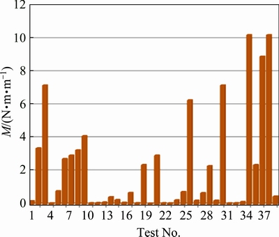
Fig. 5 Bending moment experienced by Cu/steel clad during ISF
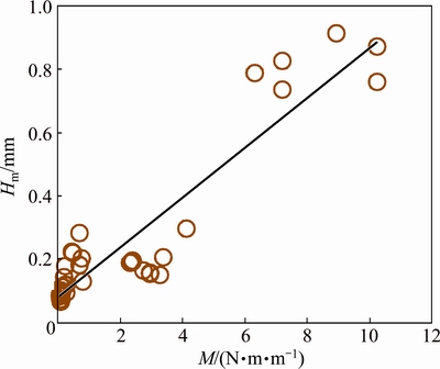
Fig. 6 Correlation between bulge height and bending moment
Table 5 compares the effect of parameters on bulging in the Cu/steel clad sheet (present study) and in a monolithic Al sheet (previous study by the authors [11]). This comparison is drawn on the basis of maximum bulge height (Hmax). This is worth noticing that the bulge-parameter trend for Cu/steel clad sheet in most respects differs from that for the monolithic Al sheet, as expected. For instance, the bulge height in monolithic sheet consistently decreases with the increase in diameter whereas the bulge height in multi-layered clad sheet increases or decreases depending on the step size chosen. The influence of step size in the two types of sheet metals is in complete disagreement. The other effects can be compared from Table 5. In fact, layers in the clad sheet owing to different hardening behavior (e.g., K of steel: 438 MPa and K of Cu: 398 MPa at room temperature) and unequal elastic constants (e.g., E of steel: 212 GPa and E of Cu: 119 GPa at room temperature) experience unequal elastic relaxation upon unloading, which most likely accounts for the discrepancies listed in Table 5.
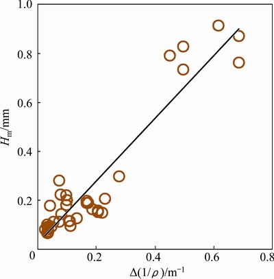
Fig. 7 Correlation between bulge height and curvature change
Moreover, the temperature range of annealing for the Cu and steel could be another possible reason for the differences highlighted in Table 5. In the present study, the Cu/steel clad sheet was annealed at 700 ��C (at maximum) as further increase in the temperature led to delamination of Cu. The recrystallization temperature for steel is about 735 ��C and that for Cu is about 540 ��C. The given temperature of 700 ��C is high enough to realize complete recrystallization in Cu while the same is insufficient for such a transformation in steel [22]. This discrepancy in the recrystallization of steel and Cu can easily lead to stress gradient in the bonded sheet, thus complicating the bulging behavior of Cu/steel aggregate. On the other hand, such an issue intrinsically cannot occur in a monolithic sheet like Al [10].
Table 5 Comparison between bulge-parameter trend in Cu/steel clad sheet and monolithic Al sheet [10]
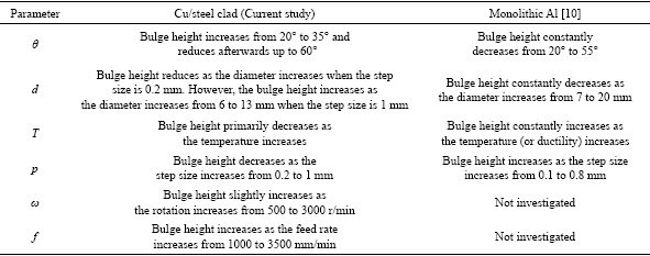
Table 6 Suitability of bulge formula proposed for monolithic sheet [10] to predict bulging in Cu/steel clad sheet
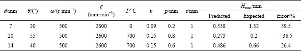
To predict the maximum bulge height (Hmax) in the monolithic sheets, am empirical formula has been proposed by HUSSAIN et al [10]. This model takes the material type into account by considering hardening exponent as material property. In order to examine the suitability of this model to predict bulging in the present Cu/steel clad sheet, the bulge height was estimated against the given conditions and was compared with the experimental one. As can be observed from Table 6, the prediction error is rather high (26%-60%), which means that the model proposed for the monolith sheet metal(s) cannot accurately predict the bulging behavior of clad sheet(s). Further, this confirms that the bulging behavior of multi-layered clad sheet is essentially different from that of monolithic sheet.
6 Conclusions
(1) Bulging in the layered sheet is sensitive to forming conditions. The use of large tool diameter, high step size and medium annealing temperature is conducive to control bulging. The response surfaces provide further guideline in this regards.
(2) Bending under tension analysis reveals that the bending moment has controlling effect on the formation of bulge. Further, the moment depends upon the forming conditions and bulging increases (i.e., bulge height from 0.07 to 0.91 mm) as the bending moment increases (from 0.046 to 10.24 N��m/m).
(3) The behavior of bulging as the function of bending moment is governed by a linear law. This law includes important forming parameters and, therefore, can be used to predict and control bulge formation in the Cu/steel clad sheet.
Acknowledgements
The authors are thankful for the financial help and technical support that King Abdulaziz University provided for this research work.
Nomenclatures
��1
Total strain that sheet endures in applied load direction
��1
Total stress that sheet endures in applied load direction
��y
Yield stress
��a
Strain due to stretching
��a
Stress due to stretching
��b
Strain due to bending
��b
Stress due to bending
C
Slope of true stress-strain curve when ��1=��1a
t
Thickness of sheet after forming
t0
Initial thickness of sheet
y
Distance of an element from neutral axis
��0
Curvature radius of neutral axis
n
Hardening exponent
K
Strength coefficient
E��
Elastic modulus in plane strain deformation
E
Elastic modulus in uniaxial tension
��
Poisson ratio
d
Tool diameter
r
Tool radius
��
Wall angle
��
Tool rotation
p
Step size
T
Annealing temperature
References
[1] HAGAN E, JESWIET J. A review of conventional and modern single point sheet forming methods [J]. Proc IMechE Journal of Engineering Manufacture, 2003, 217: 213-225.
[2] JURISEVIC B, KUZMAN K, JUNKAR M. Water jetting technology: An alternative in incremental sheet metal forming [J]. International Journal of Advanced Manufacturing Technology, 2006, 31: 18-23.
[3] JURISEVIC B, SAJN V, KOSEL F, JUNKAR M. Introduction of laminated supporting tools in water jet incremental sheet metal forming [J]. International Journal of Advanced Manufacturing Technology, 2008, 37: 496-503.
[4] EMMENS W C. Water jet forming of steel beverage cans [J]. International Journal of Machine Tools & Manufacture, 2006, 46: 1243-1247.
[5] XU D, WU W, MALHOTRA R, CHEN J, LU B, CAO J. Mechanism investigation for the influence of tool rotation and laser surface texturing (LST) on formability in single point incremental forming [J]. International Journal of Machine Tools & Manufacture, 2003, 43: 37-46.
[6] DONG G J, ZHAO C C, CAO M Y. Flexible-die forming process with solid granule medium on sheet metal [J]. Transactions of Nonferrous Metals Society of China, 2013, 23(9): 2666-2677.
[7] JESWIET J, MICARI F, HIRT G, BRAMLEY A, DUFLOU J, ALLWOOD J. Asymmetric single point incremental forming of sheet metal [J]. Annals CIRP, 2005, 54: 623-650.
[8] LI J C, LI C, ZHOU T. Thickness distribution and mechanical property of sheet metal incremental forming based on numerical simulation [J]. Transactions of Nonferrous Metals Society of China, 2012, 22(S1): s54-s60.
[9] HAN F, MO J H, QI H, LONG R F, CUI X, LI Z W. Springback prediction for incremental sheet forming based on FEM-PSONN technology [J]. Transactions of Nonferrous Metals Society of China, 2013, 23(4): 1061-1071.
[10] HUSSAIN G, GAO L, HAYAT N. Forming parameters and forming defects in incremental forming of an aluminum sheet: Correlation, empirical modeling and optimization: Part A [J]. Materials & Manufacturing Processes, 2011, 26: 1546-1553.
[11] HUSSAIN G, AL-GHAMDI KA, KHALATBARI H, IQBAL A, HASHEMIPOUR M. Forming parameters and forming defects in incremental forming process: Part B [J]. Materials & Manufacturing Processes, 2014, 29: 454-460.
[12] AL-GHAMID K A, HUSSAIN G. The pillowing tendency of materials in single-point incremental forming: Experimental and finite element analyses [J]. Proc IMechE Journal of Engineering Manufacture, 2014, doi:10.1177/0954405414530906.
[13] ISIDORE B B L, HUSAIN G, SHAMCHI S P, KHAN W A. Prediction and control of pillow defect in single point incremental forming using numerical simulations [J]. Journal of Mechanical Science & Technology, 2016, 30: 2151-2161.
[14] MORI T, KURIMOTO S. Press-formability of stainless steel and aluminum clad sheet [J]. Journal of Materials Processing Technology, 1996, 56: 242-253.
[15] KIM J, THOMSON P. Forming behaviour of sheet steel laminate [J]. Journal of Materials Processing Technology, 1990, 22: 45-64.
[16] AL-GHAMDI K A, HUSSAIN G. Parameter-formability relationship in ISF of tri-layered Cu-steel-Cu composite sheet metal: Response surface and microscopic analyses [J]. International Journal of Precision Engineering and Manufacture, 2016, 17: 1633-1642.
[17] LEEDY K D, STUBBiNS J F. Copper alloy-stainless steel bonded laminates for fusion reactor applications: Tensile strength and microstructure [J]. Materials Scienec and Engineering A, 2001, 297: 10-18.
[18] FANG Y, LU B, CHEN J, XU D K, OU H. Analytical and experimental investigations on deformation mechanism and fracture behavior in single point incremental forming [J]. Journal of Materials Processing Technology, 2014, 214: 1503-1515.
[19] MARCINIAK Z, DUNCAN J L, HU S J. Mechanics of sheet metal forming [M]. Oxford: Butterworth-Heinemann (UK), 2002.
[20] EMMENS W C, BOOGAARD A H. An overview of stabilizing deformation mechanisms in incremental sheet forming [J]. Journal of Materials Processing Technology, 2009, 209: 3688-3695.
[21] HSUN H U. Elastic Properties of cold-rolled and annealed sheets of phosphorous steel having high normal plastic anisotropy [J]. Texture of Crystalline Solids, 1980, 4: 111-127.
[22] CALLISTER W D. Materials science and engineering: An introduction [M]. New York: John Wiley & Sons, 2007: 253-293.
����������̽��㸲ͭ��Ĺİ�������������������Ӱ��
Khalid A. AL-GHAMDI1, G. HUSSAIN2
1. Department of Industrial Engineering, King Abdulaziz University, Jeddah, Saudi Arabia;
2. Department of Mechanical Engineering, Eastern Mediterranean University, Cyprus
ժ Ҫ���İ��ǽ������ι���(ISF)������������ʧЧ��һ��ȱ�ݡ����о���Ŀ���ǣ�(1)�˽⸲ͭ����ְ�Ĺİ���Ϊ���������֮��Ĺ�ϵ��(2)���������Թİ���Ӱ�죬����ͼ�ó���ػ�����Ϊ�ˣ�����һϵ�еĽ������κ�����ʵ�顣�����������״��ĵĹİ��γɶԳ������������У�����ͨ�������˻���ϣ�����ĵ���ֱ���Ͳ�������ISF�ӹ���ʹ�İ�������С�����������������İ��dz��ι�����ISF������ʩ���ڰ���ϵ������������õĽ���������ش�0.046���ӵ�10.24 N��m/mʱ���İ���ƽ���߶ȴ�0.07���ӵ�0.91 mm����״����еĹİ����������س����Թ�ϵ�����ϣ�ͨ�������������ؿ��Կ˷��İ�ȱ�ݣ����о�����Ĺ�ʽ������о���һ���İ�����
�ؼ��ʣ��������Σ������壻�İ����������أ���������
(Edited by Bing YANG)
Corresponding author: G. HUSSAIN; Tel: +92-938281026 (Ext. 2558); Fax: +92-938281000; E-mail: gh_ghumman@hotmail.com
DOI: 10.1016/S1003-6326(18)64920-9
Abstract: Bulge is a defect that causes geometrical inaccuracy and premature failure in the innovative incremental sheet forming (ISF) process. This study has two-fold objectives: (1) knowing the bulging behavior of a Cu clad tri-layered steel sheet as a function of forming conditions, and (2) analyzing the bending effect on bulging in an attempt to identify the associated mechanism. A series of ISF tests and bending analysis are performed to realize these objectives. From the cause-effect analysis, it is found that bulge formation in the layered sheet is sensitive to forming conditions in a way that bulging can be minimized utilizing annealed material and performing ISF with larger tool diameter and step size. The bending under tension analysis reveals that the formation of bulge is an outgrowth of bending moment that the forming tool applies on the sheet during ISF. Furthermore, the magnitude of bending moment depending upon the forming conditions varies from 0.046 to 10.24 N��m/m and causes a corresponding change in the mean bulge height from 0.07 to 0.91 mm. The bending moment governs bulging in layered sheet through a linear law. These findings lead to a conclusion that the bulge defect can be overcome by controlling the bending moment and the formula proposed can be helpful in this regards.
