
J. Cent. South Univ. (2016) 23: 869-879
DOI: 10.1007/s11771-016-3134-9

Dynamic rupture and crushing of an extruded tube using artificial neural network (ANN) approximation method
Javad Marzbanrad1, Behrooz Mashadi1, Amir Afkar1, 2, Mostafa Pahlavani1
1. School of Automotive Engineering, Iran University of Science and Technology, Tehran, Iran;
2. Faculty of Electrical, Mechanical and Construction Engineering, Department of Automotive Engineering,
Standard Research Institute (SRI), Karaj P.O. Box 31745-139, Iran
 Central South University Press and Springer-Verlag Berlin Heidelberg 2016
Abstract:
A numerical study of the crushing of thin-walled circular aluminum tubes has been carried out to investigate the crashworthiness behaviors under axial impact loading. These kinds of tubes are usually used in automobile and train structures to absorb the impact energy. Previous researches show that thin-walled circular tube has the highest energy absorption under axial impact amongst different structures. In this work, the crushing between two rigid flat plates and the tube rupture by 4 and 6 blades cutting tools is modeled with the help of ductile failure criterion using the numerical method. The tube material is aluminum EN AW-7108 T6 and its length and diameter are 300 mm and 50 mm, respectively. Using the artificial neural network (ANN), the most important surfaces of energy absorption parameters, including the maximum displacement of the striker, the maximum axial force, the specific energy absorption and the crushing force efficiency in terms of impact velocity and tube thickness are obtained and compared to each other. The analyses show that the tube rupture by the 6 blades cutting tool has more energy absorption in comparison with others. Furthermore, the results demonstrate that tube cutting with the help of multi-blades cutting tools is more stable, controllable and predictable than tube folding.
Key words:
thin-walled structure; rupture; energy absorption; ductile failure criterion; neural network��
1 Introduction
The passengers�� safety during probable accidents has become an important issue, due to increase of vehicles speed. Thin-walled tubes are extensively used as energy absorbers during vehicle accidents. The use of lightweight materials has increased recently to reduce the weight of vehicle body and the fuel consumption [1]. Multiple alternatives such as advanced high-strength steels, aluminum or magnesium alloys, and composite materials have been proposed to replace mild steel applications in the automotive structure [2]. Due to its low weight and being a corrosion resistor, aluminum alloy is a good alternative that can be recycled with much less required energy than that needed to produce primary aluminum. The prospect shows that for example, in Europe, the aluminum consumption will face the increase of 30% until 2020 [3].
The energy absorption and the maximum impact load of an aluminum crash box during a crash depend on many parameters such as geometry, strain-rate sensitivity, plastic deformation history of metalwork, porosity of materials, temperature during crash, boundary conditions and impact energy (mass and velocity of the striker).
Splitting circular metal tubes is an efficient energy absorption method to dissipate undesirable energies in many structures such as automotive ones. Use of splitting process has many advantages in comparison to other energy absorber systems since there are various failure mechanisms in the whole process such as bending, stretching and tearing. Nia and Hamedani [4] investigated deformations and energy absorption capacity of thin-walled tubes with various section shapes (circular, square, rectangular, hexagonal, triangular, pyramidal and conical) both experimentally and numerically. The tubes have the same volume, height, average section area, thickness and material, and are subjected under axial quasi static loading. The results of simulations are in good agreement with the experimental data and show that the section geometry has considerable effect on the energy absorption. The circular tube has the most energy absorption capacity and the most average force among all investigated sections.
Reid [5] studied different deformation modes such as splitting, inversion and folding in circular tubes subjected to axial loadings. It was shown that plastic deformation is a major mechanism for dissipating kinetic energy. The mechanisms which involve fracture such as splitting process can use plastic deformation as a good energy absorber. Zhou and Wang [6] studied the coalescence splitting mechanism of crack-weakened brittle materials subjected to compressive load by using the improved near crack line analysis method and simplification of crack development mechanism. They presented some analytical relations to estimate stress components near the crack line. Cheng and Altenhof [7] developed and used a cutting device in quasi-static axial compressive tests of square cross section AA6061-T6 extrusions to generate a cutting deformation mode of the extrusions. For the extrusions which experienced the cutting deformation mode, two energy dissipating mechanisms were observed, namely, a cutting deformation mechanism and petalled sidewall outward bending mechanism. The bending energy absorption mechanism accounted for approximately 25% of the total energy absorption.
Jin et al [8] studied the load/displacement and energy-absorption characteristics of AA6061-T6 round extrusions under a cutting deformation mode via experimental testing. Tube length appeared to have no significant influence on the load/displacement response of the extrusions, which experienced the cutting mode of deformation. The average crush force efficiency for extrusions, which experienced the cutting mode of deformation, was approximate 0.95 independent of tube length. The average CFE of specimens which experienced progressive folding and global bending deformation modes were 0.66 and 0.20, respectively.
Majumder et al [9] investigated experimentally a cutting deformation mode of AA6061 T4 and T6 round extrusions with two different wall thicknesses of 1.587 and 3.175 mm under quasi-static loading conditions. Clean cutting behavior was observed for the extrusions with a T6 temper and wall thickness of 1.587 mm and for extrusions with a T4 temper and wall thickness of 3.175 mm. Jin and Altenhof [10] proposed an analytical deformation model for axial cutting of circular tubes by using a cutter with multiple blunt blades and compared their model with experimental measurements. The effect of the friction force was included in the proposed solution and the steady-state axial cutting force was determined through the use of the principle of virtual power.
Yuen et al [11] demonstrated the experimental data on the axial splitting of circular aluminum extrusions under a blast loading condition using a cutting tool and deflector configurations were performed with a good degree of repeatability and controllability. The thick-walled extrusions exhibit better repeatability and controllability during the tests. The increase in wall thickness provided more contact surface area between the extrusions and the blade hence making them less susceptible to misalignment. In general, the length of cut depth was observed to increase with the increase of charge mass used and decreased with the increase in wall thickness.
Niknejad et al [12] derived some theoretical relations to predict the axial force during the splitting process on circular metal tubes. They introduced a new theoretical model of defamation that divides the splitting process into five different stages. This study showed that when the semi-angle of die increases, the maximum splitting force and the steady force increase. By increasing the number of initial slits, tube diameter and tube wall thickness, the splitting force increases, too. Also, the axial load of the splitting process is enhanced when the initial slits length decreases.
Marzbanrad et al [13] considered the stress�Cstrain sensitivity effect on box behavior during a crash by creating elastic and plastic boundary conditions instead of rigid boundary conditions on the bottom of a crash box. In addition, the effect of elastic and plastic boundary conditions on the energy absorption of circular tubes under impact force is numerically investigated. The ductile failure criterion is employed to accurately obtain crashworthiness simulation results. The results reveal that the use of elastic boundary can change deformation mode and decrease the maximum impact force.
Generally, there are two methods to develop rupture process in tubes:
1) Use of cone-shaped rigid rod
2) Use of cutting tools
Although the energy absorption is sufficient when the rupture occurs by the conical rod, this kind of process has its own disadvantages:
1) Crush force efficiency reduction due to high maximum force at the beginning of process;
2) Unpredictable petal numbers and rupture path;
3) Variable amount of energy absorption and non-repeatability of the process;
4) Numerous problems with using this method as an energy absorption system in vehicles during collision because of heavy weight and high required space above the conical rod which must be embedded inside the vehicle.
Nowadays, artificial intelligence has extensive application in system identification and optimization problems. The solution method of system identification and optimization problem has become fast and accurate, owe to the spread of meta-heuristic algorithms. Marzbanrad and Pahlavani [14] used genetic algorithm (GA) to make a lumped mass to be applied in vehicle impact problems. Moreover, Marzbanrad and Ebrahimi [15] used ANN to study impact in foam filled profiles.
Rupture with the help of cutting tools is studied in two ways. One is the case when the load is applied to the cutting tool and the tool moves while the tube is stationary; the other one is when the cutting tool is fixed and the impact strikes the tube (the tube is moving). The second case is less applicable in comparison to the first one because of packaging problems and cutting tool fixing. In this work, three cases are modeled numerically: tube folding between two rigid flat plates and tube rupture with the help of 4 blades and 6 blades cutting tools when the impact is applied axially to the aluminum tube. In the present study, the important parameters of energy absorption including the maximum axial force and the crushing force efficiency during impact is obtained and compared in different velocities and thicknesses using artificial neural network. In fact, ANN is used to make a model which can be applied to estimate energy absorption parameters accurately for the conditions under which their information is not available in experimental tests.
2 Modeling
2.1 Hooputra��s ductile damage (HDD) criterion
In 2004, a group of researchers in Germany��s BMW automobile company, directed by Hooputra, proposed a comprehensive approach for predicting a component failure based on macroscopic strains and stresses [16]. This approach requires the use of a number of different failure mechanism representations, such as necking (due to local instabilities), as well as ductile and shear fracture. All the failure criteria have been developed in a way to include the effect of nonlinear strain paths. They experimentally obtained the material parameters of aluminum alloy EN AW-7108 T6 for quasi-static and dynamic cases, and using these criteria could accurately predict the failure of aluminum parts. The Hooputra��s ductile fracture criterion is based on Kolmogorov��s mathematical model [17], and represents the equivalent strain as a function of the stress triaxiality. Regarding the non-uniform effect of increasing the equivalent strain, affected by the stress triaxiality growth, three dependent parameters are considered for the isotropic materials. For these materials, the criterion is defined as:
 (1)
(1)
 (2)
(2)
 (3)
(3)
where  sm,
sm,  and �� are the fracture equivalent strain, mean stress, von Mises equivalent stress and the stress triaxiality, respectively. Furthermore, d indicates damage variable, which changes from raw material to ruptured material. Symbols a, b, and c are the material parameters which are experimentally extracted from waisted tensile specimen [18], Erichsen��s cupped test, and three-point bending test of double chamber extrusion component. In the above-mentioned tests, the values of stress triaxiality are 1/3, 2/3 and 3-1/10, respectively.
2.2 Numerical analysis
ABAQUS/Explicit software is used to perform the numerical simulations. Four-node shell elements with reduced integration (ABAQUS S4R) are employed to describe the circular tube tests with aluminum alloy EN AW-7108 T6. The isotropic hardening properties (true stress vs plastic strain) of this material are shown in Fig. 1 [16].
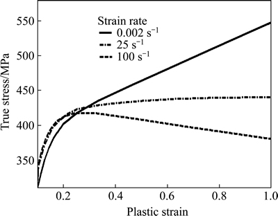
Fig. 1 Stress-strain curve at different strain rates [16]
This model was previously used for impact of aluminum alloy EN AW-7108 T6 tube with a circular cross section and for aluminum alloy 6063-T4 tube with a square cross section during folding and verified with the help of experimental results [13, 19]. A sample of model results in comparison to experimental results is shown in Fig. 2.
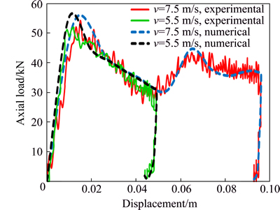
Fig. 2 Comparison diagrams of model and experimental results of force versus displacement for tube axial impact with velocities of 7.5 and 5.5 m/s during folding [19]
Moreover, this model is used for quasi-statically tube cutting simulation with cutting tools based on experimental study of Majumder et al [9]. To make this model of cutting tools, similar dimensions of four-blade (model A) tools of MAJUMDER is used. The tube length is 300 mm, its external diameter is 50.8 mm, its thickness is 3.175 mm and is made up of aluminum alloy AA6061-T4. Comparison diagram of axial force versus displacement during quasi-statically cutting by the cutting tool is shown in Fig. 3. As it is seen, the model results have proper accuracy in comparison to the experimental study.
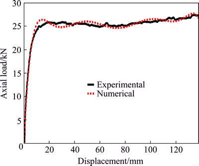
Fig. 3 Comparison diagram of model and experimental results [9] of force versus displacement for quasi-statically tube cutting with help of cutting tools
In this work, three kinds of strikers are used to strike the aluminum alloy tube, including a rigid flat plate for tube folding and two kinds of solid cutting tools with 4 and 6 blades to provide cutting mode in the tube. The cutting tools with 4 and 6 blades are shown in Fig. 4. The thicknesses of cutting edges are chosen in a way that their sum in 4 and 6 blades are equal to each other, namely:
 (4)
(4)
The depth of both cutting tools is the same and equals to 30 cm.
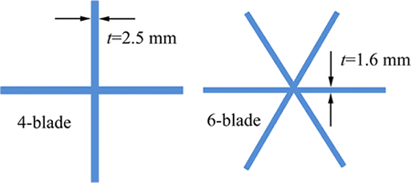
Fig. 4 Front view of cutting tools with 4 and 6 blades
All the strikers are regarded as a point mass of 100 kg with different initial velocities of v=6, 8 and 10 m/s in one direction. Due to the striker��s rigidity assumption and also restraining it in all directions except the axial one (a longitudinal direction), the mass is considered as lumped for simplicity in modeling. The contact between tube and striker is defined as the surface-to-surface interaction with a friction coefficient of 0.2. Besides, double surface self-contact is defined considering the whole tube surface with a friction coefficient of 0.15 [16]. The material is strain-rate- sensitive aluminum alloy (EN AW-7108 T6) with elastic modulus and mass density of E=70 GPa and ��=2700 kg/m3, respectively. The tube dimensions include diameter of D=50 mm, lengths of L=300 and 400 mm and wall thicknesses of t=2.0, 2.5 and 3.0 mm.
Frequency parameters are used to estimate the energy absorption capability of thin-walled tubes. Some of the most important parameters are obtained in this work:
1) Total energy absorption (TEA, EAbsorbed)
EAbsorbed is defined as the tube external work which can be calculated as:
 (5)
(5)
where P(d) is a function of crash load based on the tube displacement (d).
In fact, the area under the force-displacement diagram must be calculated to obtain total energy absorption.
2) Peak crush force
Peak crush force is demonstrated by Pmax and is the maximum force applied axially to the part.
3) Mean crush force (pm)
 (6)
(6)
It is obtained via division of total energy absorption to total crush displacement (dt).
4) Crush force efficiency (CFE, Ecf)
 (7)
(7)
5) Specific energy absorption (SEA, Ase)
 (8)
(8)
where m is the tube mass which absorbs energy during impact.
6) Total time
The time duration which the crushing or cutting process lasts from the impact beginning to its ends is called the total time.
3 Results of impact simulations
Figures 5-7 display distributions on Hooputra��s ductile damage variable (D) from raw to ruptured material. Figure 5 shows the case that the alloy aluminum tube, which is placed between two rigid plates (one is fixed and the other moves in one direction), is struck with velocities of 6, 8 and 10 m/s. It shows the moment when the maximum displacement of striker occurs. This figure relates to the tube with the length of 300 mm and the thickness of 2.5 mm. It is clear that the damage is more in high velocities and usually happens at tube ends. Tube damage during folding at either ends depends on different factors including tube length, tube diameter, tube thickness, tube material, velocity and mass of the striker, supporter type and etc., hence its prediction is difficult [13].
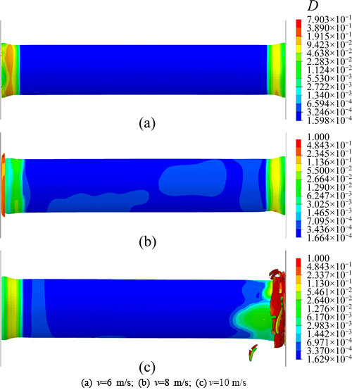
Fig. 5 Distributions of damage variable (D) for tube folding between two flat plates with length of 300 mm and thickness of 2.5 mm at different velocities:
Figure 6 relates to the case that the aluminum alloy tube is supported to the rigid flat plate from one side and from the other side, it is struck axially by the 4-blade rigid cutting tool (according to Fig. 4) with velocities of 6, 8 and 10 m/s. Tube dimensions are as the previous case. As it is evident, the cutting tool feed inside the tube increases with the increase of velocity. Also, the rupture happens in a path which is predictable.
Figure 7 is similar to the previous case with the exception that instead of 4-blade cutting tool, the 6 blades one (Fig. 4) is used.
As it is known, the energy absorption of tube cutting process is done through three manners:
1) Energy absorption at the wedge area of cutting tool when the cutting wedge penetrates inside the tube sheet;
2) Energy absorption due to friction between cutting tool surfaces and the tube;
3) Energy absorption due to plastic deformation inside the tube.
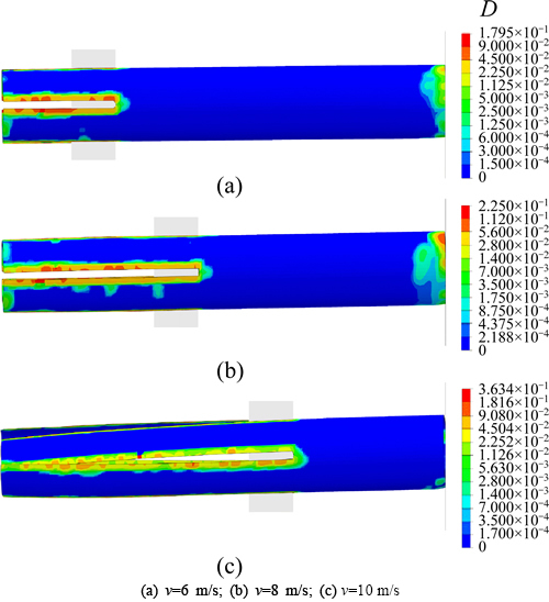
Fig. 6 Distributions of damage variable (D) for tube rupture with length of 300 mm and thickness of 2.5 mm at different velocities by 4-blade cutting tool:
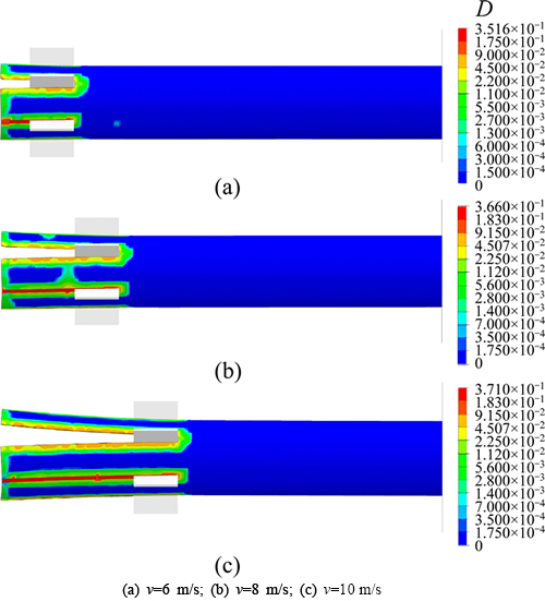
Fig. 7 Distributions of damage variable (D) for tube rupture with length of 300 mm and thickness of 2.5 mm at different velocities by 6-blade cutting tool:
The tool feed inside the tube with 4-blade cutting tool (Fig. 6) is more than the 6-blade one (Fig. 7) due to lower friction between tool and tube. The reason of lower friction is because of smaller contact surface of 4-blade tool than the 6-blade one. Besides, a significant plastic deformation is not seen in the ruptured tube in the case of 4 blades tool (Fig. 6). However, for the 6-blade tool (Fig. 7), because the blades are closer to each other in comparison to the 4-blade one, the provided sheets of tube rupture bend towards outside of the tube center, which increases the energy dissipation.
In Fig. (8), diagrams of axial load in terms of dispalcement are compared for the process of tube folding between two rigid flat plates and tube rupture by4-and 6-blade cutting tools. As it is observed, high maximum load, high range and irregular variations are some specifications of folding between two rigid plates. However, for rupture by 4-and 6-blade tools, the maximum load is low, and the variations range is lower and more regular. Tube thickness is 2 mm for this figure.
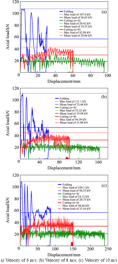
Fig. 8 Comparison of axial load-displacement diagrams of tube folding between two plates and tube rupture by 4-and 6-blade cutting tools for tube with length of 300 mm and thickness of 2 mm:
All the obtained measures for three cases of tube folding between two plates and tube rupture by 4-and 6-blade cutting tools are presented in Table 1.
4 Artificial neural network (ANN)
4.1 Approximation method
Artificial neural networks (ANN) is one of the most powerful tools which can recognize and model complicated input-output systems [20]. Neural networks are composed of simple elements operating in parallel. These elements are inspired by biological nervous systems. As in nature, the connections between elements largely determine the network function. It can be trained a neural network to perform a particular function by adjusting the values of the connections (weights) between elements. Typically, neural networks are adjusted or trained, so that a particular input leads to a specific target output. Figure 9 depicts a typical ANN block diagram which has been used in the present survey. In fact, the proposed network is regulated based on comparison between the output and the target (crush parameters), until the network output matches the target. The neural network can be known as a simple nonlinear mapping between the input and output parameters. The ANN contains a certain number of processors with interconnected weights and the final values of these weights are determined during the training period.
The ANN developed in this work is illustrated in Fig. 10. All input vectors of suggested ANN have 3 elements namely type of crash tool, impact velocity and thickness. The number of these input vectors is equal to that of respondents. The proposed ANN has 5 neurons in its hidden layer each of which has a hyperbolic tangent sigmoid transfer function. The mentioned ANN includes 4 targets namely maximum displacement, maximum force, specific energy absorption and crush force efficiency which have been calculated via finite element simulations.
Mathematically, for an interval of [-10, 10], it compresses all of its inputs to a range from -1 to +1, as it is shown in Fig. 11(a). In the output layer, there is just 1 neuron equal to the success value of horizontal strategy implementation. This function gives back whatever it takes. The diagram of this function is shown in Fig. 11(b).
Actually, the model most important purpose is to reduce this performance function as much as possible. To do so, Levenberg-Marquardt back propagation algorithm has been found very efficient. This algorithm enables the network to update its parameters (i.e. weights and biases) in order to reduce performance function value. Parameter updating in turn is done through an iteratively training manner.
Table 1 Obtained values for three cases of tube folding between two flat plates and tube rupture by 4-and 6-blade cutting tools for 300 mm length tube

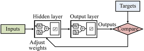
Fig. 9 ANN block diagram
Specifically, this mechanism enables the network to determine the gradient of performance function and by means of its training function updates its parameters for reducing performance function.

Fig. 10 Proposed ANN
Design of an accurate and efficient ANN requires the following steps [21]:
1) Selecting the proper architecture of the ANN, which mainly means the number and size of the hidden layers due to the fact that the size of input and output layers must be defined by the input and output of the model;
2) Selecting the training parameters, e.g. the weight adjusting rate (learning rate) and the momentum constant;
3) Selection and preparation of the suitable set of data which will be used in training and testing of the ANN;
4) Defining how many times the number of delayed output sets must be fed back to the network.
4.2 Approximation results
According to the available inputs and outputs in Table 1 and with the help of neural network, the bond between input and output data is made for impact velocities from 4 to 12 m/s and tube thicknesses of 1.5 to 3.5 mm. The calculated error for this neural network is under 5% (which is ideal for such problems). For better comparison and analysis, more important surfaces including the maximum displacement, the maximum force, the specific energy absorption and the crushing force efficiency in terms of tube thickness and striker velocity are plotted.
Figure 12 shows the surfaces in terms of initial velocity of the striker and the tube thickness during tube crushing. For the tube crushing between two flat rigid plates, the maximum displacement increases with the increase of tube thickness and striker velocity as shown in Fig. 12(a). The lower the tube thickness or the higher the impact velocity is, the more the variation rate of the maximum displacement is. In this case, with the increase of tube thickness, the maximum force increases, which is not proper as illustrated in Fig. 12(b). It should be mentioned that the increase of impact velocity doesn��t have much effect on the maximum effect and remains constant with the velocity change. With the decrease of tube thickness and increase of impact velocity, the specific energy absorption increases as can be seen in Fig. 12(c). The lower the tube thickness or the higher the impact velocity is, the more the variation rate of the specific energy absorption is. The crushing force efficiency increases with the increase of tube thickness and the impact velocity doesn��t have much effect on the efficiency as may be observed in Fig. 12(d).
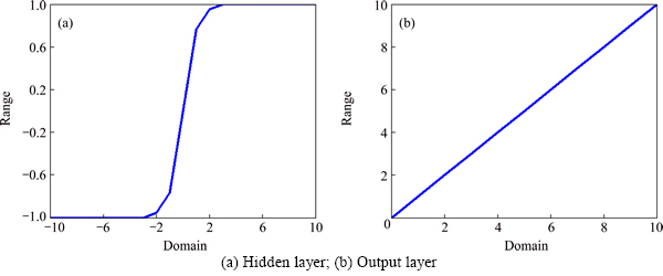
Fig. 11 function diagram:
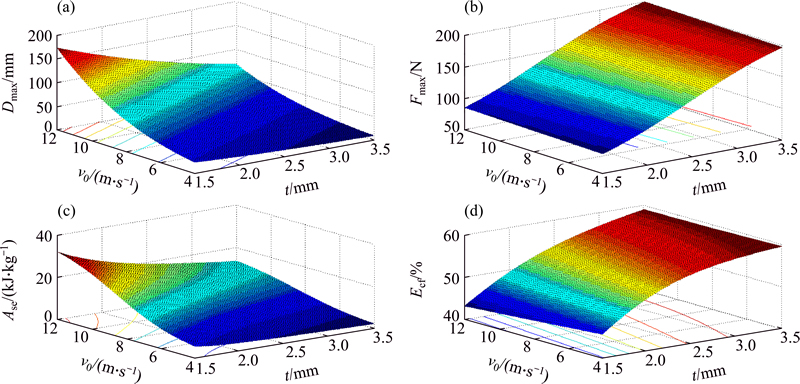
Fig. 12 Surfaces of maximum displacement of striker (a), maximum axial force (b), specific energy absorption (c) and crushing force efficiency (d) during tube crushing
Figure 13 shows the surfaces in terms of initial velocity of the impact and the tube thickness during tube rupture by 4-blade cutting tool. Maximum displacement variation for rupture by the 4-blade cutting tool as shown in Fig. 13(a) has a similar trend with crushing between two flat plates (Fig. 12(a)). The difference is that the maximum displacement for rupture by the 4-blade cutting tool has higher level than the obtained surface from the crushing between two flat plates. The trend of maximum force variation for tube cutting by the 4-blade cutting tool as illustrated in Fig. 13(b) is similar to the crushing between two flat blades (Fig. 12(b)). The difference is that for the tube cutting by 4-blade cutting tool, this force is in lower level and is more suitable. The trend and the variation of the energy absorption for the rupture by the 4-blade cutting tool as can be seen in Fig. 13(c) doesn��t have much difference with the tube crushing between two flat plates (Fig. 12(c)). No constant trend can be determined for the crushing force efficiency in case of rupture by the 4-blade cutting tool, as observed in Fig. 13(d). However, it can be said that the efficiency level in the case of rupture by the 4-blade cutting tool (Fig. 13(d)) is higher than the efficiency of crushing between two flat plates (Fig. 12(d)).
Figure 14 shows the surfaces in terms of initial velocity of the striker and the tube thickness during rupture by the 6-blade cutting tool. Maximum displacement variations for rupture by the 6-blade cutting tool as shown in Fig. 14(a) has a similar trend with crushing between two flat blades (Fig. 12(a)) and rupture by the 4-blade cutting tool (Fig. 13(a)). The difference is that the maximum displacement for the rupture by the 6-blade cutting tool is located on a surface between the one obtained from crushing between two flat plates and the one obtained from rupture by the 4-blade cutting tool. The trend of maximum force variations for the tube rupture by the 6-blade cutting tool as illustrated in Fig. 14(b) is similar to the tube crushing between two flat plates (Fig. 12(b)) and rupture by the 4-blade cutting tool (Fig. 13(b)). The difference is that for the tube rupture by the 6-blade cutting tool, this force is in a surface between rupture by the 4-blade cutting tool and crushing between two flat plates and is closer to the maximum force of rupture by the 4-blade cutting tool. The trend and variations of the specific energy absorption for the case of rupture by the 6-blade cutting tool as can be seen in Fig. 14(c) doesn��t have much difference in comparison to the tube crushing between two flat plates (Fig. 12(c)) and the rupture by the 4-blade cutting tool (Fig. 13(c)). A constant trend cannot be determined for the efficiency of the crushing force of the rupture by the 6-blade cutting tool as observed in Fig. 14(d). However, it can be said that the rupture efficiency by the 6 blades cutting tool (Fig. 14(d)) is higher than both crushing between two flat plates (Fig. 12(d)) and rupture by the 4-blade cutting tool (Fig. 13(d)).
Generally, it may be concluded that the variations trend in the plotted surfaces of maximum displacement and maximum force in terms of velocity and thickness of the three strikers are similar. Surfaces of the specific energy absorption have similar trends for every three striker and are very close, numerically. The variations trend in the surfaces of crushing force efficiency doesn��t follow a specific algorithm; however, their values in blade cases are more than the crushing cases. Also, the values of 6-blade are more than the 4-blade.
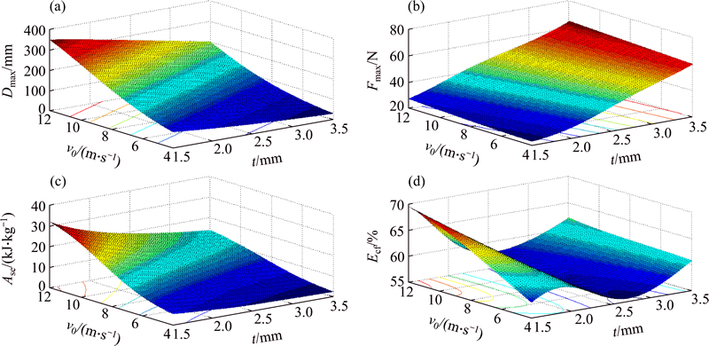
Fig. 13 Surfaces of maximum displacement of striker (a), maximum axial force (b), specific energy absorption (c) and crushing force efficiency (d) during tube rupture by 4-blade cutting tool
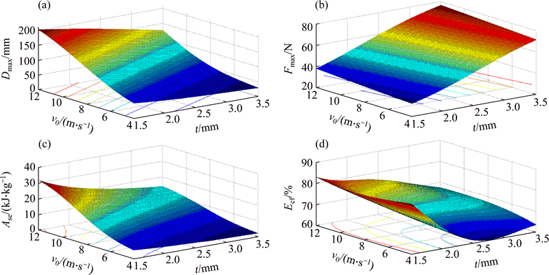
Fig. 14 Surfaces of maximum displacement of striker (a), maximum axial force (b), specific energy absorption (c) and crushing force efficiency (d) during rupture by 6-blade cutting tool
5 Conclusions
damage numerical analyses (cutting deformation and folding) of a circular tube are carried out based on ductile failure criterion to accurately obtain crashworthiness simulation results. With the help of neural network, surfaces of important parameters of energy absorption in terms of velocity and tube thickness are obtained. Using the trained neural network, the target parameters are calculated properly and accurately for those input parameters, the experimental results of which are not available and the variations trend of target parameters are inspected completely.
1) Generally, the impact velocity has direct relationship with maximum displacement, total energy absorption and specific energy absorption for different tube dimensions and various impact velocities during tube folding between two flat rigid plates and tube rupture by 4-and 6-blade cutting tools. The maximum axial load remains constant with the increase of velocity. Tube thickness has inverse relationship with the maximum displacement and the specific energy absorption, and has direct relationship with the maximum and mean axial loads. Total energy absorption remains constant with the increase of tube thickness.
2) When the tube rupture occurs with the help of multi-blades cutting tools, the rupture path and displacement measure are predictable while they are unpredictable during tube folding between two flat plates. Behavior of diagrams of axial load in terms of displacement and time is stable, controllable and repeatable for tube rupture by the multi-blades cutting tools while it is not possible for tube folding between two flat plates.
3) Considering the higher maximum force and lower crush force efficiency of folding between two plates, this case is the worst choice among three described cases. For rupture case by the 4-blade cutting tool, the maximum axial load is lower than the 6 blades one and the crush force efficiency of the 6-blade cutting tool is more than the 4-blade one. However, since the maximum displacement of the 6 blades cutting tool is less and also there is not much difference between maximum axial loads of 4-and 6-blade cutting tools, the best choice is the 6-blade cutting tool. It seems that multi objective optimization method is required considering the tube impact conditions to obtain length, thickness, diameter and proper material of the tube as an energy absorber.
References
[1] Zhou Y, Lan F, Chen J. Crashworthiness research on S-shaped front rails made of steel�Caluminum hybrid materials [J]. Thin-walled Structures, 2011, 49(2): 291-297.
[2] Lu G, Yu T. Energy absorption of structures and materials [M]. Elsevier, 2003: 215-248.
[3] European Aluminum Association. Aluminum in cars [R]. 2008.
[4] NIA A A, HAMEDANI H J. Comparative analysis of energy absorption and deformations of thin walled tubes with various section geometries [J]. Thin-walled Structures, 2010, 48(12): 946-954.
[5] Reid S. Plastic deformation mechanisms in axially compressed metal tubes used as impact energy absorbers [J]. International Journal of Mechanical Sciences, 1993, 35(12): 1035-1052.
[6] Zhou X p, Wang J h. Study on the coalescence mechanism of splitting failure of crack-weakened rock subjected to compressive loads [J]. Mechanics Research Communications, 2005, 32(2): 161-171.
[7] Cheng Q, Altenhof W. Load/displacement and energy absorption performances of AA6061-T6 tubes under a cutting deformation mode [J]. International Journal of Crashworthiness, 2005, 10(6): 621-633.
[8] JIN Y, Altenhof S W, Kapoor T. An experimental investigation into the cutting deformation mode of AA6061-T6 round extrusions [J]. Thin-walled structures, 2006, 44(7): 773-786.
[9] Majumder A, Altenhof W, Vijayan V, Jin S Y. Quasi-static axial cutting of AA6061 T4 and T6 round extrusions [J]. Proceedings of the Institution of Mechanical Engineers, Part L: Journal of Materials Design and Applications, 2008, 222(3): 183-195.
[10] Jin S Y, Altenhof W. An analytical model on the steady-state deformation of circular tubes under an axial cutting deformation mode [J]. International Journal of Solids and Structures, 2011, 48(2): 269-279.
[11] YUEN C K S, ALTENHOF W, OPPERMAN C J, NURICK G N. Axial splitting of circular tubes by means of blast load [J]. International Journal of Impact Engineering, 2013, 53: 17-28.
[12] Niknejad A, Rezaei B, Liaghat G H. Empty circular metal tubes in the splitting process��Theoretical and experimental studies [J]. Thin-walled Structures, 2013, 72: 48-60.
[13] Marzbanrad J, Keshavarzi A, Aboutalebi F H. Influence of elastic and plastic support on the energy absorption of the extruded aluminium tube using ductile failure criterion [J]. International Journal of Crashworthiness, 2014, 19(2): 172-181.
[14] Marzbanrad J, Pahlavani M. Calculation of vehicle-lumped model parameters considering occupant deceleration in frontal crash [J]. International Journal of Crashworthiness, 2011, 16(4): 439-455.
[15] Marzbanrad J, Ebrahimi M R. Multi-objective optimization of aluminum hollow tubes for vehicle crash energy absorption using a genetic algorithm and neural networks [J]. Thin-walled Structures, 2011, 49(12): 1605-1615.
[16] Hooputra H, Gese H, Dell H, Werner H. A comprehensive failure model for crashworthiness simulation of aluminium extrusions [J]. International Journal of Crashworthiness, 2004, 9(5): 449-464.
[17] Kolmogorov W. Spannungen deformationen bruch [M]// Metallurgija. 1970: 230.
[18] Hill M R, Panontin T L. Micromechanical modeling of fracture initiation in 7050 aluminum [J]. Engineering Fracture Mechanics, 2002, 69(18): 2163-2186.
[19] Marzbanrad J, Keshavarzi A. A numerical and experimental study on the crash behavior of the extruded aluminum crash box with elastic support [J]. Latin American Journal of Solids and Structures, 2014, 11(8): 1329-1348.
[20] Demuth H, Beale M, Hagan M. Neural network toolboxTM 6 user��s guide matlab [M]. The MathWorks, 2013.
[21] Omar T, Eskandarian A, Bedewi N. Vehicle crash modelling using recurrent neural networks [J]. Mathematical and computer Modelling, 1998, 28(9): 31-42.
(Edited by FANG Jing-hua)
Received date: 2015-04-17; Accepted date: 2015-10-13
Corresponding author: Amir Afkar, PhD, Researcher; Tel: +98-9122046355; E-mail: afkar@iust.ac.ir
Abstract: A numerical study of the crushing of thin-walled circular aluminum tubes has been carried out to investigate the crashworthiness behaviors under axial impact loading. These kinds of tubes are usually used in automobile and train structures to absorb the impact energy. Previous researches show that thin-walled circular tube has the highest energy absorption under axial impact amongst different structures. In this work, the crushing between two rigid flat plates and the tube rupture by 4 and 6 blades cutting tools is modeled with the help of ductile failure criterion using the numerical method. The tube material is aluminum EN AW-7108 T6 and its length and diameter are 300 mm and 50 mm, respectively. Using the artificial neural network (ANN), the most important surfaces of energy absorption parameters, including the maximum displacement of the striker, the maximum axial force, the specific energy absorption and the crushing force efficiency in terms of impact velocity and tube thickness are obtained and compared to each other. The analyses show that the tube rupture by the 6 blades cutting tool has more energy absorption in comparison with others. Furthermore, the results demonstrate that tube cutting with the help of multi-blades cutting tools is more stable, controllable and predictable than tube folding.
