
Article ID: 1003-6326(2005)06-1242-06
Microstructure and properties of
cutting magnesium-brass containing no lead
HUANG Jin-song(�ƾ���)1, PENG Chao-qun(����Ⱥ)1, ZHANG Si-qi(������)2,
HUANG Bai-yun(�Ʋ���)1, MA Chang-song(������)2
(1. State Key Laboratory of Powder Metallurgy, Central South University,
Changsha 410083, China;
2. School of Materials Science and Engineering, Central South University,
Changsha 410083, China)
Abstract:
A new environmental friend cutting brass containing magnesium instead of lead was produced by casting, extruding and drawing. Its microstructure was observed and its mechanical, chemical and cutting properties were stutied. The results show that the global secondary particles which are brittle and soft intermetallics, distribute in grains and on grain boundries, which is helpful for improvement of cutting ability of the brass. The tensile strength, yield strength, elongation and area reduction of halfhard magnesium-brass are 550MPa, 280MPa, 16.30%, 32.4%, respectively. The cutting ability of magnesium-brass corresponds to that of lead-brass C3604 judged by the size and appearance of chips of alloy and by the cutting force. The magnesium-brass has excellent corrosion resistance.
Key words:
lead; magnesium; brass; cutting; microstruture; property CLC number: TG146 ; ; ; ; ; ; ; ; ; ; ; ; ;Document code: A;
1 INTRODUCTION
Lead-brass has excellent cutting ability, mechanical and physical properties and is one of the most widely used copper alloys. The occupation ratio of brass tube to all kinds of tubes reaches 90% in developed countries. The cutting lead-brass is a dual-phase brass and fine lead particles distribute dispersively in grains and on grain bounries. The lead in wasted brass can easily be leached and dissolved into soil. If the wasted lead-brass is burned in air, the lead will become porous PbO. While the lead-brass is used to produce water potable, the lead will become lead ion and dissolve into solution under the influence of matters in water, which will seriously damage the health of human body[2]. So the lead-brass is seriously considered and its application will be limited gradually. To decrease the noxious effect of lead on human body, scientific researchers systematically studied the corrosion properties of brass[3, 4]. They found many methods to decrease the noxious effect of lead in brass, for example to increase the anti-corrosion ability of lead-brass by adding some tin or nickel into brass[5] or eliminating the leachable lead in lead-brass[6]. Apparently, the noxious effect of lead in brass can��t be thoroughly eliminated with these ways. The developed countries have legislated to gradually forbid the use of lead-brass in water portable fittings, toys and household appliances. The lead-brass will be replaced by lead free brass finally. The cutting lead free brass was studied early and some reports[7-11] and patents[12, 13] about lead free brass containing bismuth were published, and lead free copper/graphite composite was developed[14]. Eight lead free(or low lead) brass materials containing bismuth have been developed in USA until 2000. A few patents about the lead free brass containing bismuth were applied recently and NB series products were developed in Japan[15]. Series of low lead brass rods are saled in Japan. By domestic price report of metals in Fabruary, 2005 , the cost of raw materials of lead free brass containing bismuth is much higher than that of lead-brass, which makes the bismuth-brass have difficult to replace lead-brass and only be used while requiring low lead. After comparison of cost accounting of cutting brass with that of cutting steel by International Copper Association Ltd[16], the comprehensive cost of cutting brass is cheeper than that of cutting steel. More and more cutting brass is used to produce car fittings and the market share of cutting steel is gradually replaced by cutting brass. Although the lead free brass containing silicon was investigated, its cutting ability is lower[17], and the study on lead free brass containing bismuth has no independent intellectual property[18]. The study on lead free brass containing antimony has made great progress, and its patent was applied in China and in USA. The authors of this paper will study the cutting ability and microstructure of lead free brass containing magnesium based on the cutting mechanism of cutting lead-brass and development thought on lead free brass containing antimony, focusing on magnesium element which is rich in resources and cheep.
2 EXPERIMENTAL
2.1 Materials
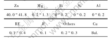
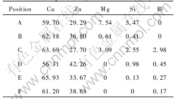
The raw materials are commercial pure copper, zinc, magnesium, bismuth, silicon and alumminium. The chemical composition of lead free brass containing magnesium is listed in Table 1.
Table 1 Chemical composition of magnesium-brass(mass fraction, %)
2.2 Experimental equipments
A GW-0.01-50/4J-D non-core intermediate frequency inducing furnace, a 3150kN extruder, a single chain horizontal drawer, a POLYAR-MET optical microscope, a KYKY-Amray scanning electron microscope(attaching EDAX energy dispersive spectrum) and a CSS-44100 multi-purpose materials mechanical tester were used in the experiments.
2.3 Experimental procedures
The block metals were put into the graphite crucible in intermediate frequency inducing furnace and were smelted. After the molten metal was fully stirred and the metal elements distributed homogeneously, the molten metal was poured into the steel model and the ingot was obtained. The ingots were machined and then hot-extruded at 500��. The hot-extruded rods were drawn on the single chain horizontal drawer. The microstructural samples were sectioned from the extruded rod. The extruded rods were machined to be elongation examples, elastic modulus examples, corrosion examples and wear and tear examples. The cutting experiment was conducted on an ordinary lathe. The cutting ability was compared in appearance and size of chips and the cutting force.
3 RESULTS AND DISCUSSION
3.1 Optical microstructure
The optical microstructural samples were sectioned along crosswise and lengthwise direction, respectively. After the samples were ground and finished, they were eroded by FeCl3-HCl solution. The eroded samples were observed under a POLYAR-MET optical microscope. Fig.1 and Fig.2 show the optical microstructures of magnesium-brass along crosswise and lengthwise direction, respectively. As shown in Fig.1 and Fig.2, the magnesium-brass is a dual-phase copper alloy, and the gray phase is �� and the dark phase is ��. It is observed from Fig.1 that the grains are slightly elongated along the extruded direction and the grain size keeps almostly unchanged, which indicates that the deformed grains only recover and don��t recrystallize while magnesium-brass is hot-extruded at 500��, so the elongated microstructure is reserved. From Fig.2, it is known that the two phases ��, �� are fine and distribute homogeneously, and the grains are elongated along specified direction, which indicates that the coarse grains of magnesium-brass are broken and elongated along specified direction while the alloy was drawn at room temperature. On one hand, the grains of magnesium-brass are elongated along drawing direction and flattened along perpendicular direction while the alloy rod is drawn. One the other hand, during deformation, the dislocations in magnesium-brass multiply, intertwist together and form submicrostructures, which refines the grains of magnesium-brass and will result in work-hardening effect in magnesium-brass.
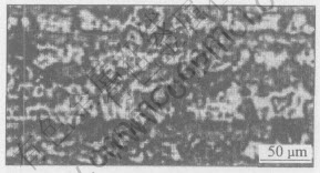
Fig.1 Longitudinal optical microstructure of as-hot-extruded magnesium-brass
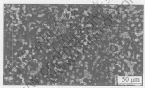
Fig.2 Transverse optical microstructure of as-drawn magnesium-brass
3.2 SEM microstructure
Fig.3 shows the SEM images of as-drawn magnesium-brass. It is shown in Fig.3 that the microstructure of magnesium-brass consists of gray phase and black phase. It is known from Cu-Zn binary phase diagram that the black phase under SEM is �� phase because it is easy to be eroded and contains much more zinc. The gray phase under SEM is �� phase because it is harder to be eroded than �� phase and contains less zinc.
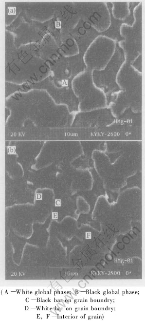
Fig.3 SEM images of as-drawn magnesium-brass and positions of EDS
There are many dispersive second particles distributing in grains and on grain boundries. To qualitatively identify the phases in alloy and quantitatively identify the chemical composition of phases, the energy dispersive spectra were conducted at different positions in Fig.3. The positions are indicated in Figs.3(a) and (b), respectively. The results of EDS are listed in Table 2.
Table 2 EDS results of magnesium-brass at different positions(mass fraction, %)
As shown in Fig.3 and listed in Table 2, the diameter of white global second particles is about 2��m and the ratio of Cu��Zn��Mg in A is 60��30��8. Judged by the appearance, distribution and ratio of elements in the particle, the white second phase in A is Cu-Zn-Mg intermetallic. The diameter, which is a little less than that in A, of gray global second particles is about 2��m and the ratio of Cu��Zn in the phase of B is 62��37. Judged by the appearance, distribution and ratio of elements in the particle, the gray second phase in B is Cu-Zn intermetallic, but its crystal structure is unclear and needs further study. The ratio of Cu to Zn in C and E is larger, so the phases in C and E are �� phase judged by Cu-Zn binary phase diagram. The fact that the contents of bismuth and silicon are higher results from impurities segregating on the black bars in C on grain boundry, which can lower the energy of system. Bismuth and silicon segregate on the grain boundries as impurities. The position of E is interior of grain and the impurities segregate on grain boundry, so there are little impurities there. The ratio of Cu to Zn is low, and from Cu-Zn binary phase diagram, it can be concluded that the phase in F is �� phase. The phase in D is white and distributes along grain boundry, which maybe results from bad conductivity of sample for SEM and the electrons aggregattion on the surface of the sample. From the microstructure and the EDS results, it can be concluded that magnesium mainly distributes on grain boundry and there is little magnesium in �� and �� phase. The intermetallic containing magnesium distributes in grain and on grain boundry. The low solubility of magnesium in �� and �� phase, weak strengthening effect of magnesium in �� and �� phase and soft and brittle intermetallic containing magnesium distributing in grain and on grain boundry result in the chip breaking while magnesium-brass is cut, the size of chips is decreased, and the cutting ability of magnesium-brass is increased effectively.
3.3 Mechanical property
The mechanical properties of magnesium-brass are listed in Table 3.
Table 3 Mechanical properties of magnesium-brass and lead-brass
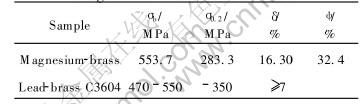
As listed in Table 3, the area redution and elongation of magnesium-brass are 32.4% amd 16.30%, respectively, which indicates the plasticity of the alloy is excellent. On one hand, the solubility of magnesium in magnesium-brass is low, and its strengthening effect is small, which makes the plasticity of magnesium keep at a stable value. On the other hand, soft and brittle global intermetallic particles containing magnesium distributing in grain and on grain boundry are small(about 2��m), which will not apparently decrease the plasticity of magnesium-brass.
The tensile strength, yielding strength and elongation of lead-brass C3604 are 470-550MPa(less than 550MPa), 350MPa and 7%, respectively. As listed in Table 3, the tensile strength and yielding strength of magnesium-brass are 550MPa and 280MPa. Apparently, the yielding strength of magnesium-brass(280MPa) is lower than that of lead-brass C3604. The reason why the yielding strength of magnesium-brass is lower than that of lead-brass C3604 is that the elements of alloy bring about many impurities which segregate on the grain boundries, for example, bismuth and silicon segregate on grain boundries. The impurities will drcrease the strength of brass severely. The brittle intermetallic in grain will also decrease the yielding strength of alloy. By the theory of strength of metals[19], the second phase distributing in grain will strengthen the alloy, but the strengthening effect is relative to appearance and strength of the particle itself, etc. Here the strength of the particle is the key factor. As shown in Fig.3, although the global second particles dispersively distribute in grain and on grain boundry, the particles are brittle and soft, so the brittleness and softness of particles decrease the yielding strength of magnesium-brass.
3. 4 Electrochemistry corrosion resistance
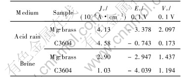
The electrochemistry corrosion experimental results of magnesium-brass and lead-brass are listed in Table 4. As it is known from the corrosion theory of metals, the anti-corrosion ability of the alloy is the best, while its corrosion rate is less than 0.02mm/a. The anti-corrosion ability of the alloy is better, while its corrosion rate is 0.02-0.1mm/a. The anti-corrosion ability of the alloy is good, while its corrosion rate is 0.1-0.5mm/a. The developed brass has good anti-corrosion ability in acid and salt, but the anti-corrosion ability of alloy is better in salt than that in acid.
Many factors have influence on metal corrosion. The factors are relative to the metal itself, for example, the composition, and to the circumstances, for example, the corrosion medium. The potential of Cu is positive, so it is stable in many kinds of media, which is based on its chemical stability. So both magnesium-brass and lead-brass have excellent anti-corrosion ability. Comparatively, the potential of magnesium is negative(-2.34V) and its chemical property is active. The oxide film of magnesium produced in corrosion medium is sparse and porous, and the ratio of molecular volume of MgO to that of magnesium is less than 1, so the sparse and porous oxide film of magnesium can not protect matrix[20]. The particles among interior and exterior of grains increase the potential among different phases, which makes it easy to form corrosional microcell and decrease the anti-corrosion ability of the brass.
Table 4 Results of electrical chemical corrosion tests
3.5 Cutting ability
The macrostructures of chips of magnesium-brass and lead-brass C3604 are shown in Fig.4. The chips of magnesium-brass and lead-brass C3604 are both small. The chips of lead-brass C3604 are long and thin needle-like. The chips of magnesium-brass are sheetlike in ��C�� shape. Their internal surface is smooth and their surface is covered by a layer of metal fluff. The cutting process of magnesium-brass is smooth, and the cutting force is stable with little fluctuation. The machined surface of alloy is smooth, and the surface roughness is small. By the cutting mechanism of metal[21, 22], fine lead particles dispersively distribute in grain and on grain boundry for lead-brass C3604. There are many lead particles on the contacted line of knife-edge. The dispersively distributed lead particles can easily break chips and decrease the binding and welding of knife-edge with lead particles, by the way, the chips are broken to little ones. Because the melting point of lead is low
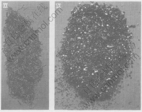
Fig.4 Chips of lead-brass(C3604)(a) and magnesium-brass(b)
(327.5��), the contacted area of knife-edge with chips is heated and local contacting area is easily molten in very short time(thermal brittleness), which helps to change the appearance of chips, and the melten lead has lubrication effect on the knife-edge, so the cutting ability of lead-brass C3604 is excellent. From the mechanical properties of magnesium-brass, it can easily be found that the intermetallic containing magnesium which dispersively distributes in brass, is brittle and soft. During cutting process, the intermetallic particles are broken under the shearing force while they contact with the knife-edge. The stress would easily accumunate on the tip of the broken intermetallic particles contacted with metal, which drives the crack to produce and propagate in the brass easily. So the chips are broken to small ones. On the other hand, the brittle and soft intermetallic particles can hinder the binding of chips with knife-edge, which can effectively improve the cutting ability of alloy.
4 CONCLUSIONS
1) There are white and black global second particles in grain and on grain boundry. Those particles are brittle and soft intermetallic and help to improve the cutting ability of alloy.
2) The tensile strength, yielding strength, elongation and area reduction of magnesium-brass are 550MPa, 280MPa and 16.30% and 32.4%, respectively. The comprehensive mechanical properties are excellent.
3) Judged by the cutting force during cutting process and the appearance and size of chips, the cutting ability of magnesium-brass is similar to that of lead-brass.
4) The developed brass has excellent anti-corrosion ability in acid and salt, but the anti-corrosion ability of alloy is better in salt than that in acid.
REFERENCES
[1]BAI Ding. Brass water portable and faucet[J]. Metals World, 2003(1): 7. (in Chinese)
[2]Korshin G V, Ferguson J F, Lancaster A N. Influence of natural organic matter on the corrosion of leaded brass in potable water[J]. Corrosion Science, 2000, 42: 53-66.
[3]�Zrnek D, Wood T K, Hsu C H, et al. Corrosion control using regenerative biofilms (CCURB) on brass in different media[J]. Corrosion Science, 2002, 44(10): 2291-2302.
[4]Gronostajski Z J. Correlation between stress-strain relation and phase transformation in copper alloys [J]. Journal of Materials Processing Technology, 2001, 119(1-3): 244-250.
[5]Sohn S, Kang T. The effects of tin and nickel on the corrosion behavior of 60Cu-40Zn alloys[J]. J Alloys Compounds, 2002, 335: 281-289.
[6]Myerson A S. Treating brass components to eliminate leachable lead[P]. US Patent 6191210.
[7]Hagiwara K, Yamazaki M. Development of ��KEEPALLOY��, lead-free copper alloy[J]. Journal of Japan Copper and Brass Research Association, 2000, 39(1): 1-7. (in Japanese)
[8]Sadayappan M. Mechanical properties of seBiloy��(C89550) [J]. AFS Transactions, 2000, 108: 571-578.
[9]Matsumoto T, Furuya M, Okubo T, et al. Drilling of lead free brass alloy ��ECOBRASS��[J]. Journal of Japan Research Institute for Advanced Copper-base Materials and Technologies, 2002, 41(1): 76-80. (in Japanese)
[10]Ando T, Atsumi T, Yoshikawa Y. Improvement of machinability of bismuth substituted free-cutting brass[J]. Journal of Japan Research Institute for Advanced Copper-base Materials and Technologies, 2002, 41(1): 97-101. (in Japanese)
[11]Plewes J T, Loiacono D N. Free-cutting copper alloys contain no lead[J]. Advanced Materials and Process, 1991, 140(4): 23-27.
[12]Hiroyuki T. Lead-free, free-cutting brass alloy material and production method thereof[P]. Japan Patent 2003-277855, 2003.
[13]Hisashi T, Keiichiro O, Yoshito S. Lead-free copper base alloy material[P]. Japan Patent 2000-169919, 2000.
[14]Rohatgi P K, Nath D, Kim J K. Corrosion and dealloying of cast lead-free copper alloy/graphite composite[J]. Corrosion Science, 2000, 42: 1553-1571.
[15]YANG Xiao-chan. The lead-free and low lead brasses were developed by Japan[J]. Progress in Modern Materials, 2002(11): 8. (in Chinese)
[16]Kundig K J A. The cost of brass used for car fittings is lower than that of steel[J]. Nonferrous Metals(Part of Metallurgy), 1997(2): 44-45. (in Chinese)
[17]PANG Jin-shan, XIAO Yin-xin. Study of nonleaded easy-cutting brass[J]. Journal of Guangdong University of Technology, 2001, 18(13): 63-66.
[18]WANG Zhi-jian. Study on copper alloy in drinking water pipe[J]. Hunan Nonferrous Metals, 2003, 19(1): 31-33.
[19]HU Geng-xiang, QIAN Miao-geng. Physical Metallurgy[M]. Shanghai: Shanghai Science and Technology Press, 1985. 303.
[20]ZHANG Si-qi, HUANG Jin-song. Melting and Casting for Nonferrou Metals[M]. Beijing: Chemical Industry Press, 2005. 3-8.
[21]HUANG Shu-tao, JIA Chun-de, YU Jun-yi. Study on chip-deformation mechanism in high-speed orthogonal turning-milling[J]. Manufacturing Technology and Machine Tool, 2003(9): 70-72.
[22]ZHANG Bai-lin, YANG Qing-dong, CHEN Chang-nian. High speed cutting technology and its application[J]. Mechanical and Electrical Engineering Technology, 2003(9): 70-72.
(Edited by YANG Bing)
Foundation item: Project (05JJ30194) supported by the Natural Science Foundation of Hunan Province, China
Received date: 2005-01-11; Accepted date:2005-09-26
Correspondence: HUANG Jin-song, PhD; Tel: +86-731-8830614; E-mail: hjsjzh@126.com, hjingsong@mail.csu.edu.cn
