

J. Cent. South Univ. (2021) 28: 398-417
DOI: https://doi.org/10.1007/s11771-021-4611-3

Lubrication characteristics of cycloid pin wheel transmission of RV reducer
HAN Ju(����)1, 2, LI Wei(����)1, QIAO Ze-long(������)2
1. School of Mechanical Engineering, University of Science and Technology Beijing, Beijing 100083, China;
2. School of Mechanical Engineering, North China University of Science and Technology, Tangshan 063021, China
 Central South University Press and Springer-Verlag GmbH Germany, part of Springer Nature 2021
Abstract:
In order to analyze the lubricating characteristics at different meshing points in the cycloid pin wheel transmission process, the cycloid gear teeth were discretized, combined with the kinematic analysis of the cycloid pin gear transmission and the contact analysis of the gear teeth. The progressive mesh densification method (PMD) was used to numerically solve the film thickness. The influence of the design parameters and process parameters on the lubrication characteristics was analyzed. The elastohydrodynamic lubrication and mixed lubrication characteristics at different contact points were obtained. The optimal meshing area of the cycloid gear tooth was determined, and the film thickness ratio, contact load ratio, maximum contact pressure at different points, average film thickness and roughness after contact deformation were analyzed. The conclusion of this study provides effective guidance for the research on the modification of cycloid gear teeth.
Key words:
cycloid pin wheel transmission; tooth modification; lubrication characteristics��
Cite this article as:
HAN Ju, LI Wei, QIAO Ze-long. Lubrication characteristics of cycloid pin wheel transmission of RV reducer [J]. Journal of Central South University, 2021, 28(2): 398-417.
DOI:https://dx.doi.org/https://doi.org/10.1007/s11771-021-4611-31 Introduction
The cycloid pinwheel transmission mechanism is the most important transmission component of the RV reducer, with characteristics of high transmission accuracy, large transmission ratio, compact structure, and long service life. It is widely used in miniature instruments, robots, and testing instruments [1]. To guarantee the transmission accuracy of the cycloid pin wheel drive, the time of disassembly and assembly must be reduced, and usually, grease lubrication is used. The lubrication characteristics of the mechanism directly affect the transmission efficiency, contact fatigue and service life [2], so it is necessary to research the lubrication characteristics of the cycloid pin wheel transmission.
There are few studies on the lubrication characteristics of cycloid pin wheel transmission. As early as 1997, ZHAO et al [3] used the minimum film thickness empirical formula to solve the minimum film thickness through numerical calculation and obtained the film thickness ratio. The lubricating state from the root to the top of the tooth was determined. JIANG et al [4, 5] first studied the elastohydrodynamic lubrication transmission of cycloid pin wheel under isothermal steady-state. The multi-grid method was used to calculate the pressure and film thickness. The minimum film thickness was calculated under the isothermal transient state and compared with the minimum film thickness under steady-state. The single rough peak and valley against oil film were studied under time-varying conditions. The influence of pressure, peak-to-peak value, and wavelength on oil film pressure distribution were analyzed and compared with the results under smooth conditions. WEI et al [6] established a mixed lubrication model based on the actual working conditions of the RV reducer, taking into account the transient effects of macro geometry, contact load, actual tooth surface roughness, and contact area of the cycloid gear and pin wheel. The effects of different factors such as load, curvature radius, entraining velocity were analyzed. SUN et al [7] and ZHU et al [8] established a mathematical model of cycloid pin wheel line contact elastohydrodynamic lubrication, studied the effects of different factors, such as load, speed, and modification on the transmission, and analyzed the characteristics of starved lubrication. None of the above works systematically studied the transient mixed lubrication characteristics of cycloid pin wheel transmissions.
In engineering practice, almost all contact surfaces are rough and usually work in mixed elastohydrodynamic lubrication (EHL) state, which is caused by direct contact of the asperities on rough surfaces. ZHU et al [9] proposed a numerical solution for point EHL taking into account 3D real machining roughness, and then ZHU et al [10] and HU et al [11] developed the model to effectively deal with the problem of coupling between asperities contact and lubrication. Later, many researchers have contributed to the improvement and applications of the model. LIU et al [12] investigated the effects of differential scheme and mesh density on EHL film thickness based on the numerical solution. WANG et al [13] developed a deterministic numerical model for simulation of mixed lubrication in point contacts. ZHU et al [14] studied many aspects of numerical solutions of thin-film and mixed EHL, such as effects of computational mesh density, differential schemes, converged and accurate numerical solutions. HE et al [15-17] studied the characteristics of plasto-elastohydrodynamic lubrication (PEHL) and conducted experiments and numerical research on the Stribeck curves for lubricated counterformal contacts. In recent years, great progress has been made in numerical methods of mixed lubrication, including Newton-Raphson method [18], coupled differential deflection method [19], multi-grid (MG) method [20], semi-system approach [21] and progressive mesh densification (PMD) method [14, 22].
It is well known that lubricating performance is significantly affected by transient behavior. Transient elastohydrodynamic lubrication occurs when the meshing of transmission parts undergoes rapid changes in velocity, load, and geometry. Due to the importance of transient lubrication, many scholars have conducted in-depth research on related issues. A numerical model based on a multi- stage method and Fast Fourier Transform (FFT) algorithm to simulate the transient lubrication evolution of the mechanism during start- stop was developed by ZHAO et al [23, 24]. LU et al [25] studied the influence of contact geometry, speed, and especially the load on the lubrication characteristics during the gearing meshing process taking into account the 3D roughness. WANG et al [26] studied the transient mixed lubrication characteristics of helical bevel gears. The effects of parameters such as contact load, curvature radius, entraining and sliding speed on the lubrication performance were investigated.
The kinematics of cycloid pin wheel transmission is relatively complicated. In the present work, the lubrication characteristics were analyzed between the cycloid gear teeth and the pin teeth during the entire contact process. In order to facilitate the study of dynamic changes in the meshing process, the meshing area between the cycloid gear tooth and the pin tooth is discretized. Discrete points in the working area of cycloidal pin gear transmission are taken for analysis and the points with poor lubrication conditions are identified. Considering the actual morphology of the contact surface, mixed lubrication characteristics are researched.
2 Key parameters of cycloidal pin wheel drive elastohydrodynamic lubrication
The RV reducer belongs to a kind of two-stage planetary gear transmission system. The first stage transmission is an involute planetary gear transmission, and the second stage transmission is a cycloid pin wheel transmission. There is feedback between the two stages. In the second stage transmission, the cycloid gear revolves under the drive of the crankshaft. At the same time, the cycloid gear rotates around its center due to the meshing of the cycloid gear��s teeth with the pin wheel teeth. In theory, the cycloid pin wheel transmission is a pure rolling form, but to compensate for manufacturing errors, facilitate assembly, and leave gaps for grease, etc., the cycloid gear needs to be modified [27]. The modified cycloidal pin gear transmission does not meet the pure rolling conditions. There is relative sliding during the contact between the cycloid gear and the pin wheel teeth, but the sliding speed is very small. It is still treated as pure rolling form due to the fact that the present work does not focus on the flash temperature problem, but the modification factor is considered in the derivation of the tooth profile equation of the cycloid.
The tooth profile modification of the cycloid gear is implemented in combination with the machining principle of the cycloid gear. The profile equation of the cycloidal wheel after modification can be obtained as follows:
 (1)
(1)
where Zc and Zp are the teeth number of cycloid gears and pin wheels, respectively; e and e* are the eccentric distance and the modified eccentric distance between the center of cycloid gear and pin wheel, respectively; Rp and  are the radius and the modified radius of central circle of pin wheel, respectively; Rrp and
  are the radius and the modified radius of pin tooth, respectively; K1 and
  are the short amplitude coefficient and the modified short amplitude coefficient of cycloid gear, respectively; S* is the operator of the modified short amplitude coefficient; ��Rp is the modification amount of radial-moving; ��Rrp is the modification amount of equidistant; ��e is the modification amount of tooth height. And =Rp+��Rp, =Rrp+��Rrp, e*=e+��e, K1=Zp/Rp, =[Zp(e+��e)]/(Rp+��Rp), S*=
 .
.
The calculation formula of the curvature radius of the cycloid gear tooth profile is as follows:
 (2)
(2)
It can be deduced that the equivalent curvature radius of the cycloid and pin wheel is as follows:
 (3)
(3)
2.1 Entraining speed of cycloid drive
Although the modified cycloid pin gear no longer meets the pure rolling condition, the relative sliding speed is very low, so it is still assumed that the cycloid pin gear drive is pure rolling contact and the entraining speed U is as follows:
 (4)
(4)
where U1 and U2 are the speeds of the two contact surfaces in the direction of the common tangent surface, respectively, and U1=U2.
In Figure 1, ��in and ��out are the angular velocity of input shaft and output shaft, respectively; ��1 and ��2 are the rotational angular velocities of central gear and planetary gear, respectively; ��in is equal to ��1 due to the fact that the central gear is fixed on the input shaft; ��a and ��pin are the rotational angular velocities of cycloid gear and pin gear, respectively; ��H' is the revolution angular velocity of planet carrier; ��H is the rotational angular velocity of crank shaft.

Figure 1 Entraining speed diagram:
Through the mechanism transformation method, it can be derived:
 (5)
(5)
 (6)
(6)
where Z1 and Z2 are the teeth number of the central gears and planetary gears, respectively; Zc and Zp are the teeth number of the cycloid gears and pin wheels, respectively. When the pin wheel housing is fixed and the planet carrier is output, ��pin=0, ��a=��H', ��2=��H, and Zp=Zc+1. ��p is the relative angular velocity when the motion of the cycloid gear is converted from planetary motion to fixed axis motion, then ��p=��H-��a=(Zp/Zc)��H, ��H=��Nin/30. Nin is the rotational speed of crank shaft and it can be used as the input speed of the cycloid-pin wheel transmission. As is shown in Figure 1, U=Uccos��=  ��pcos��.
Combining the geometric relationship and the derivation of the tooth profile equation, the expression of entraining speed is as follows:
 (7)
(7)
where xK and yK are the abscissa and ordinate of the meshing point K on the cycloid gear in the coordinate system xOcy, respectively.
2.2 Load analysis of cycloid pin wheel drive
According to the deformation coordination conditions of the cycloid pinwheel, it can be seen from Figure 2 that when the cycloid gear teeth and the pin teeth mesh, f is the swing angle of the cycloid gear caused by the force at the meshing points; li is the moment that Fi acts on the center of the cycloid gear, then the deformation caused by Fi is lif. Assume that the force of each meshing point is proportional to the deformation caused, that is:
 (8)
(8)
where lmax is the moment that Fmax acts on the center of the cycloid gear, so lmax is equal to r1. So,
 (9)
(9)
where ��i is the angle between the common normal of the i-th meshing point and the rotating arm  ,
,  [28], and Tout is the torque on the cycloid gear.

Figure 2 Cycloidal force diagram
Applying the law of sine and cosine in ��POpOi, it can be deduced:
 (10)
(10)
where ��i is the rotation angle of the i-th pin tooth relative to the rotating arm.
Considering the modification factor, the contact load per unit length on the tooth width direction is as follows:
 (11)
(11)
Figure 3 shows the curves of contact force, the equivalent radius of curvature, and entraining speed during the meshing contact. It can be seen from Figure 3 that during the transmission, the changes of key parameters are very complicated, and it is difficult to intuitively judge the changes of pressure and film thickness of elastohydrodynamic lubrication.
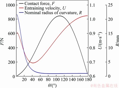
Figure 3 Curve of key parameters of cycloidal pin wheel transmission
2.3 End modification and arc modification of cycloid gear
Theoretically, the contact form between the cycloid gear tooth and the pin tooth is line contact. However, in practice, end modification and arc modification will always be performed on the cycloid gear teeth as shown in Figure 4.
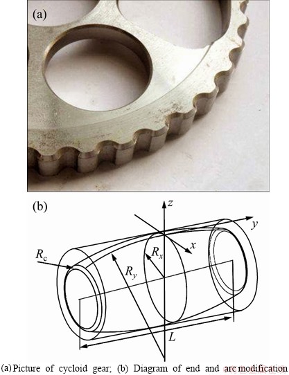
Figure 4 Modification diagram of cycloid gear tooth:
As shown in Figure 4, Ry is the arc modification radius of cycloid tooth; Rc is the end modification radius of cycloid tooth. After the modification, the contact between the cycloid gear teeth and the pin teeth will be converted from line contact to point contact. The contact area is elliptical. Assume that a and b are the semi-axes of the contact ellipse in the x and y directions, respectively.
3 Lubrication analysis of cycloidal pin wheel transmission
3.1 Equations of transient mixed EHL
Cycloid pin wheel transmission is a form of line contact. The isothermal mixed EHL model of line contact proposed by ZHU et al [29] is widely used as follows:
 (12)
(12)
where �� is the effective viscosity; �� is density of lubrication; h is film thickness. The solution domain of Eq. (12) is determined as 1.5��X��1.5 and 1.5��Y��1.5, where X=x/a, Y=y/a, and the x-coordinate coincides with the entraining speed. In order to solve this equation, the boundary conditions that p=0 and  at the edges of the solution domain, should be satisfied. The calculation of the instantaneous film thickness h at a specific location needs to consider the transient geometry, surface roughness and elastic deformation.
 (13)
(13)
where h0(t) denotes the normal gap of the two body surfaces;  and
and  are the transient geometry before elastic deformation; ��(x, y, t) is the effective roughness of two surfaces; ��(x, y, t) is the surface elastic deformation which can be computed by
 E' is the equivalent elastic modulus; �� is the entire solution domain; �� and �� are the coordinate values of the points in the solution domain, respectively.
Several pressure-viscosity models have been established based on experimental investigations and in the present work, the Roelands law [30] is adopted and expressed as follows:
 (14)
(14)
where Z' is the pressure-viscosity index and can be estimated by  ; ��' is the pressure-viscosity exponent which is a property of the lubricant; ��0 is the lubricant viscosity at ambient pressure.
The pressure density equation [31] is expressed as follows:
 (15)
(15)
where ��0 is the density of grease at ambient pressure. During the meshing process of the cycloid gear teeth and the pinteeth, the contact pressure changes with time and contact position. The load balance condition can be expressed as below:
 (16)
(16)
3.2 Numerical analysis of elastohydrodynamic lubrication of cycloid pin wheel transmission
In elastohydrodynamic lubrication analysis on the smooth interface, using the PMD [29, 32] method to calculate the film thickness, the target grid level is level IV and the number of grids is 256��256. The contact body material characteristics and the non-Newtonian characteristic parameters of the grease are shown in Table 1.
Table 1 Material characteristic parameters

Elastohydrodynamic lubrication characteristics are mainly concerned with the distribution of film thickness and pressure. Film thickness and pressure are also key parameters for subsequent investigation of interface contact performance. Figure 5 shows a cloud diagram of the smooth interface elastohydrodynamic lubrication film thickness and pressure distribution obtained by numerical calculation. x and y directions are dimensionless quantities, and ph is the nominal maximum Hertzian contact pressure. It can be seen from Figure 5 that there is a secondary peak in the pressure distribution at the outlet area of the lubricating medium. The film thickness distribution has necking, which is consistent with the characteristics of elastohydrodynamic lubrication.

Figure 5 Cloud diagram of thickness and pressure distribution of smooth interface:
3.2.1 Influence of design parameters on lubrication characteristics
1) Effect of equivalent curvature radius on lubrication characteristics
The equivalent radius of curvature is an important design parameter of the joint surface of the cycloidal pin wheel transmission mechanism. It is affected by the diameter of the tooth, short amplitude coefficient, number of teeth, etc.
It can be seen from Figure 6 that the radius of curvature of the joint surface has a great influence on the film thickness and pressure distribution, and the radius of curvature increases, and the lubricating film thickness tends to decrease. When the radius of curvature decreases, the necking zone at the outlet narrows.
As the radius of curvature increases, the secondary peak-to-peak value at the outlet increases, but the pressure value in the central region tends to decrease first and then increase.
As can be seen from Figure 6(a), in the x direction, as the equivalent radius of curvature increases, the film thickness decreases, and the necking at the outlet tends to move inward. Correspondingly, there are two pressure peaks in Figure 6(b). The position of the peak also shifts inward as the equivalent radius of curvature increases, and the peak-to-peak value of the secondary pressure increases as the radius of curvature increases. The change in pressure in the y direction changes little with the curvature, but the change in the radius of curvature has a significant effect on the film thickness in the middle of the contact zone. As the radius of curvature increases, the film thickness decreases.
The change of the peak value and position of the secondary pressure peak caused by the equivalent radius of curvature also affects the distribution and magnitude of the subsurface pressure. Figure 7 shows the contour maps of the subsurface pressure in the x direction. The maximum value appears near to Z=z/a=0.7.
The thickness of the necking film at the outlet of the lubrication zone has a greater influence on the subsurface pressure. The smaller the film thickness, the greater the subsurface pressure. And the maximum value of the corresponding subsurface pressure has an upward trend.
2) Influence of the end shape modification on the lubrication characteristics
The shape of the end is mainly rounded or chamfered. As can be seen from Figure 8, when the end is rounded, the thickness of the film and the pressure vary little with the radius of the rounded corner. Compared with rounded corner trimming, the film thickness at the end of chamfering trimming has a sharp narrowing band. The film thickness and pressure in the contact area are almost the same when the rounding of the end is different. In contrast, the film thickness of the chamfering is slightly lower than that of the rounding, especially in the y direction. When chamfering, the film thickness at the end drops sharply. The pressure distribution in the x and y directions is almost the same. The pressure peak at the end in the y direction varies with the change of modification radius, and it decreases first and then increases.

Figure 6 Film thickness and pressure curves with different equivalent radii of curvature:

Figure 7 Equivalent cloud map of subsurface pressure with different equivalent radii of curvature in x direction:

Figure 8 Variation curve of film thickness and pressure at the end modification:
Figure 9 shows the pressure distribution in the y direction on the film thickness curve when there is no end modification and end modification. It can be seen from Figure 9 that although the end modification does not eliminate the pressure peak at the end, the end rounded modification can effectively increase the thickness of the lubricating film at the end. Therefore, in the actual cycloid gear structure, the end of the gear is generally rounded. In addition, to eliminate the fluctuation of the line contact during the meshing of the cycloid gear tooth with the pin tooth, it is also considered to modify the top of the cycloid gear tooth.
3) Influence of arc top modification on the lubrication characteristics
From the above analysis, it can be seen that there are pressure peaks at the ends of the contact area, and the pressure peaks are high and the lubricating film is thin. Since the end area is originally in the stress concentration area, efforts should be made to eliminate the pressure peak at the end. By modifying the top of the arc, the pressure peak at the contact end of the cylinder with finite length can be better eliminated. After the arc-top modification, the contact between the cycloid gear teeth and the pin teeth will change from line contact to point contact. Figure 10 shows the three- dimensional cloud diagram of the film thickness and pressure distribution after arc-top modification. It can be seen from Figure 10 that after the arc-top modification, the pressure peak at the end in the y direction disappears and the higher-pressure area in the contact area is distributed in the middle of the contact area. And in the x direction, there is a secondary pressure peak and film thickness necking in the outlet area.
Figure 11 are contour clouds of film thickness with different arc radii. It can be seen from Figure 11 that as the radius of the arc-top modification increases, the elastohydrodynamic region becomes wider, the neck of the exit zone moves inward, and the pressure in the contact zone tends to decrease. The most important thing is that the pressure peak at the end in the width direction of the contact zone is better eliminated by the arc-top modification.

Figure 9 Variation curve of film thickness and pressure with or without end modification in y direction:

Figure 10 Three-dimensional cloud diagram of film thickness and pressure distribution of arc-top modification (Rx=2 mm, Ry=1000 mm):
As can be seen from the film thickness and pressure curve shown in Figure 12, although there are pressure peaks at both ends in the y direction, the pressure peak is much smaller than the middle pressure, about 55% of the middle pressure peak, which can better avoid the end damage of gear teeth caused by concentrated stress. In terms of film thickness, the film thickness in both directions increases as the radius of the arc-top modification increases, so it is more reasonable to choose a larger modification radius in practical applications. The arc-top modification has little effect on the pressure distribution and value in both directions. From the partial enlarged view, it can be seen that the pressure peak in the middle and end of the contact area decreases slightly with the increase of the arc top modification radius. The pressure peak at the end in the y direction tends to decrease with the modification radius, and decreases first and then increases.
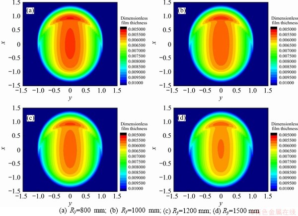
Figure 11 Contours of film thickness of different arc-top shapes (Rx=2 mm):

Figure 12 Curves of film thickness and pressure change of arc top modification:
From the above analysis, it can be concluded that the modification of the arc top has a significant effect on the contact of the gear teeth. In the contact mechanism, the line contact is changed to the point contact, which effectively eliminates the pressure peak in the width direction of the contact.
3.2.2 Effect of process parameters on lubrication characteristics
The process parameters of the RV reducer include load, speed and other working condition parameters. The influence of working conditions on the lubrication characteristics cannot be ignored. By analyzing the influence of the working condition parameters on the lubrication characteristics, it can effectively help the selection of the reducer and the determination of the operating regulations.
1) Influence of load on lubrication characteristics
The load mainly refers to the load on the cycloid gear teeth. To facilitate the study, we mainly investigate the relationship between oil film thickness and pressure distribution under the condition of normalized parameter contact area.
Figure 13 shows the equivalent cloud diagram of film thickness and pressure distribution under different unit length load. As can be seen from Figure 13, the effect of load on film thickness is more obvious, and the effect on pressure is relatively small in comparison. In the case of point contact, the pressure distribution has a horseshoe shape, and in the outlet area where the film thickness distribution at the necking region becomes wider as the pressure increases.
As can be seen in Figure 14, the film thickness and pressure curves show that, when the load increases, the film thickness decreases greatly in both x and y directions, but the corresponding pressure change is not significant.
2) Influence of the entraining velocity on the lubrication characteristics
The entraining velocity is an important process parameter that affects the film thickness. Figure 15 shows that as the entraining velocity increases, the film thickness increases. The change of the entraining velocity has little effect on the pressure distribution.

Figure 13 Equivalent clouds of film thickness under different unit lengths:

Figure 14 Variation curves of film thickness and pressure with different contact forces:

Figure 15 Variation curves of film thickness and pressure at different entraining velocities:
3.3 Dynamic elastohydrodynamic lubrication analysis of cycloid pin wheel transmission mechanism
During the transmission of the cycloid pin wheel, when the parameters such as contact force, equivalent radius of curvature and entraining speed change, the meshing state of the cycloid gear teeth and the pin teeth will change significantly. Therefore, it is necessary to comprehensively analyze the coupling between the design parameters and the process parameters. Figure 16 shows the generation principle of cycloid gear tooth profile. The modified cycloid pin wheel transmission has a main working section with �ȡ�[30��, 120��] [28, 33]. �� is the angle that the arm OOc rotates around point O, and �� in Figure 16 is the same parameter as the �� in Eqs. (1) and (10). Figure 17 shows the meshing area recommended by Ref. [28], and the area is discretized into 15 points. To ensure that the analysis area covers the meshing area, �� will change from 27�� to 125�� and the interval between adjacent points ���� will be 7��. The teeth meshing of the cycloid pin wheel drive is periodic. During the meshing process, the meshing dynamic loads can be represented by the static loads of these 15 points distributed in the gear tooth contact area. Since the position of each meshing point is determined by ��, �� can be expressed as a function of time. So the load, radius of curvature and velocity at those discrete points can be regarded as the dynamic features during the time history of meshing.

Figure 16 Generation of cycloid tooth profile

Figure 17 Points to be analyzed on working area of cycloid gear
Through the gear tooth load contact analysis (LTCA), the contact force per unit length, equivalent radius of curvature and entraining speed at the above 15 analysis points can be obtained. Taking the RV20E reducer as an example, when the load moment is 230 N��m, the cycloid gear teeth and the key parameters at the corresponding contact points of the pin teeth are shown in Table 2.
Table 2 Key parameters of contact point between cycloid gear teeth and pin teeth

It can be seen from Table 2 that the changing rules of the three key parameters at different points are inconsistent, which also makes the elastohydrodynamic lubrication characteristics of the gear tooth contact area more complicate and time-vary during the cycloid pin wheel transmission process. According to Figure 18, the film thickness and pressure performance of P1 and P4 are very different. Figures 19 and 20 show the contour maps of the film thickness and pressure change of each point of P1 �CP15.
From the contour maps of different analysis points, it can be concluded that the lubrication conditions from P1 to P4 are poor, and the lubrication conditions at those points are quite different, especially the contact area with higher pressure near the lubrication outlet of P1 and P2 are obviously larger than other points. The changes in the film thickness and pressure clouds from P5 to P15 are relatively stable from the contour maps of film thickness and pressure. Figure 21 shows the minimum film thickness (hmin) and the maximum pressure (pmax) of each point. According to the figures, the pressure and film thickness both have the tendency to decrease first and then increase. The change of the minimum film thickness from P1 to P8 is relatively sharp, and the change of minimum film thickness from P8 to P15 is relatively small. The values of the minimum film thickness from P8 to P15 are larger than those of points P1-P7. The change of the maximum pressure at each point has the same characteristics. During the gear tooth meshing process, the contact characteristics of different meshing points should change relatively smoothly, which is more in line with the requirement for excellent transmission performance. Therefore, changing the meshing area on the gear teeth of the cycloid from P1-P15 to P8-P15 can provide better transmission performance. The corresponding �� at P8 is 76��, and �� at P15 is 125��. Combining the meshing range given in Ref. [30], the optimal meshing area of the cycloid gear tooth is determined as �ȡ�[80��, 120��]. This conclusion is roughly correct, with the preliminary determination of optimized gear tooth meshing region based on the contact lubrication characteristics of gear teeth, which provides an idea for the subsequent research on the modification of cycloid gear teeth.
Figure 21 shows the film thickness and pressure distribution of the contact surface with different roughness. When considering the rough state of the contact surface, the film thickness and pressure distribution on the smooth contact surface differ greatly, and the same with the pressure in the contact area. The increase of peaks is more obvious from the original second peak to the third peak, and the peak value of the third peak at the exit area is significantly higher than the previous two peaks. In terms of film thickness, due to the contact between the asperities, the film thickness in the meshing area is mostly zero. In addition, the roughness of the contact surface has a greater influence on the film thickness and pressure. From Figure 22, it can be seen intuitively that the pressure peak increases with the increase of the roughness, and the distribution of the third peak in the meshing area is more obvious.

Figure 18 Three-dimensional cloud diagram of film thickness and pressure at different contact analysis points of cycloid gear teeth:

Figure 19 Equivalent cloud diagram of film thickness at different contact analysis points of cycloid gear teeth:
When the contact surfaces are rough, if the contact pressure is high enough, the lubrication state will generally be in a mixed lubrication state. Under the same working conditions, the more severe the lubrication conditions are, the denser the distribution of high pressure and low film thickness in the area. The increased roughness makes more asperities participate into contact, which leads to a worse lubrication state. Whether the contact surface is smoother and the contact performance is better still needs further study. This issue of the content is not the focus in the present work.
From the analysis in the previous chapters, it can be seen that the lubrication state of the main working section of the cycloidal pin gear transmission is significantly dynamic, and the lubrication state of the P8-P15 section of the gear teeth in Figure 16 is obviously superior to P1-P7. Therefore, by modifying tooth on the profile and shape, the contact region between the cycloid gear teeth and the pin teeth can be limited at P8-P15, which can effectively improve the contact lubrication characteristics of the gear teeth, thereby reducing wear, and improving the accuracy of the mechanism to maintain performance. The method of modifying the profile of the cycloid gear teeth does not belong to the research scope of this chapter. In this chapter, it is important to pay attention to the lubrication characteristics of the cycloid gear teeth with the coarse tooth surface when they mesh with the pin teeth.

Figure 20 Pressure contour cloud diagram of different contact analysis points of cycloid gear teeth:
Mixed lubrication is a lubrication regime in which lubricant films and asperities contact coexist.

Figure 21 The minimum film thickness and the maximum pressure curve at each discrete analysis point
Generally, the film thickness ratio �� is used to judge the lubrication status in engineering. There are many definitions of the film thickness ratio. In this study, the ratio of the average film thickness to the root mean square of contact surface roughness is used, that is ��=ha/�� [34], with the range from 0.01-0.05 to 0.6-1.2 under mixed lubrication [35].
It can be seen from Figure 23 that the film thickness ratio �� at each contact point of the meshing zone is between 0.65 and 0.75, indicating that the gearbox meshing zone of the cycloidal pin wheel transmission is in a mixed lubrication state when the gear teeth are rough. Moreover, the lubrication state of P8 and P9 is poor, and the contact pressure ratio and contact area ratio of the corresponding asperities are significantly higher than those of other points. The maximum contact pressure at different points in Figure 23 fluctuates greatly and has a significant three-peak shape. When the meshing area is subjected to high pressure, its roughness changes significantly, decreasing from 0.4 ��m to about 0.3 ��m.

Figure 22 Film thickness and pressure distribution of contact surfaces with different roughness:

Figure 23 Lubrication characteristics at different discrete points in working area:
4 Conclusions
1) As the radius of curvature increases, the secondary peak-to-peak value at the outlet of the elastohydrodynamic lubrication zone increases, but the pressure value in the central zone first decreases and then increases. The necking film thickness at the outlet of the lubrication zone is below the surface. The greater the pressure is, the smaller the film thickness will be. When the subsurface pressure gets higher, the maximum value of the corresponding subsurface pressure also has an upward trend.
2) The end shape modification does not eliminate the end pressure peak, but the rounded corner shape modification can effectively increase the thickness of the lubricating film at the end. Therefore, in the actual cycloid gear structure, rounded corners should be modified.
3) As the radius of the arc-top modification increases, the elastohydrodynamic zone becomes wider, the necking of the exit zone moves inward, and the pressure in the contact zone tends to decrease. Through the arc-top modification, the pressure peak at the end in the width direction of the contact area can be eliminated in a better way. Therefore, the arc-top modification of the cycloid wheel can effectively improve the contact condition and have a positive effect on avoiding the damage of the gear teeth caused by concentrated stress.
4) The effect of load on the film thickness is more obvious, and the effect on pressure is smaller in comparison. After the arc top is modified, the gear tooth contact changes from line contact to point contact. In the case of point contact, the pressure distribution shows a horseshoe shape. In terms of film thickness distribution, the film thickness necking area in the outlet area is significantly wider as the pressure increases.
5) As the entraining velocity increases, the film thickness increases, and the necking width of the exit zone also narrows accordingly. In actual work, the lubrication characteristics of the RV reducer can be improved by increasing the working speed.
6) By discretizing the main working area of the gear teeth and analyzing the lubrication characteristics of each discrete point, the conclusions is that the lubrication condition of the first half of the main working area is relatively poor; and by modifying the shape, the working area can be reduced to improve the meshing process elastohydrodynamic lubrication characteristics in the middle contact area.
Contributors
The overarching research goals were developed by HAN Ju, LI Wei and QIAO Ze-long. HAN Ju and LI Wei established the models and calculated the lubrication characteristics. HAN Ju and QIAO Ze-long analyzed the calculated results. The initial draft of the manuscript was written by HAN Ju and LI Wei. All authors replied to reviewers�� comments and revised the final version.
Conflict of interest
HAN Ju, LI Wei and QIAO Ze-long declare that they have no conflict of interest.
References
[1] WANG Hui, SHI Zhao-yao, YU Bo, XU Hang. Transmission performance analysis of RV reducers influenced by profile modification and load [J]. Applied Sciences, 2019, 9(19): 4099. DOI: 10.3390/app9194099.
[2] SHI Xiu-jiang, SUN Wen, LU Xi-qun, MA Xuan, ZHU Dong, ZHAO Bin, HE Tao. Three-dimensional mixed lubrication analysis of spur gears with machined roughness [J]. Tribology International, 2019, 140: 105864. DOI: 10.1016/j.triboint.2019.105864.
[3] ZHAO Qing, HE Shao-jun. Analysis of EHL in cycloid planetary gearing [J]. Lubrication Engineering, 1997, 22(6): 19-21.(in Chinese)
[4] JIANG Yuan-zhi, WANG You-qiang, YU Ping. The transient EHL analysis of the cycloidal pinwheel planetary gearing mechanism [J]. Lubrication Engineering, 2014, 39(12): 12-15, 23. (in Chinese)
[5] JIANG Yuan-zhi, WANG You-qiang, LU Xian-jiu. The influence of single rough peak on the elastohydrodynamic lubrication of cycloid pinwheel [J]. Machinery Design & Manufacture, 2014(12): 49-52. (in Chinese)
[6] WEI Bo, WANG Jia-xu, ZHOU Guang-wu, YANG Rong-song, ZHOU Hong-jun, HE Tao. Mixed lubrication analysis of modified cycloidal gear used in the RV reducer [J]. Proceedings of the Institution of Mechanical Engineers, Part J: Journal of Engineering Tribology, 2016, 230(2): 121-134. DOI: 10.1177/1350650115593301.
[7] SUN Zhang-dong, ZHU Cai-chao, LIU Huai-ju, SONG Chao-sheng, GU Zong-lin. Study on starved lubrication performance of a cycloid drive [J]. Tribology Transactions, 2016, 59(6): 1005-1015. DOI: 10.1080/10402004.2015. 1129569.
[8] ZHU Cai-chao, SUN Zhang-dong, LIU Huai-ju, SONG Chao-sheng, GU Zong-lin. Effect of tooth profile modification on lubrication performance of a cycloid drive [J]. Proceedings of the Institution of Mechanical Engineers, Part J: Journal of Engineering Tribology, 2015, 229(7): 785-794. DOI: 10.1177/1350650115570402.
[9] ZHU Dong, AI Xiao-lan. Point contact EHL based on optically measured three-dimensional rough surfaces [J]. Journal of Tribology, 1997, 119(3): 375-384. DOI: 10.1115/1.2833498.
[10] ZHU Dong, HU Yuan-zhong. The study of transition fromelastohydrodynamic to mixed and boundary lubrication [C]// Proceedings of the 1999 STLE/ASME Tribology Surveillance, Park Ridge: STLE/ASME, 1999: 150-156. https://www.researchgate.net/publication/283921871_ The_study_of_transition_from_full_film_elastohydrodynamic_to_mixed_and_boundary_lubrication.
[11] HU Yuan-zhong, ZHU Dong. A full numerical solution to the mixed lubrication in point contacts [J]. Journal of Tribology, 2000, 122(1): 1-9. DOI: 10.1115/1.555322.
[12] LIU Yu-chuan, WANG Q J, WANG Wen-zhong, HU Yuan-zhong, ZHU Dong. Effects of differential scheme and mesh density on EHL film thickness in point contacts [J]. Journal of Tribology, 2006, 128(3): 641-653. DOI: 10.1115/1.2194916.
[13] WANG Wen-zhong, HU Yuan-zhong, LIU Yu-chuan, WANG Hui. Deterministic solutions and thermal analysis for mixed lubrication in point contacts [J]. Tribology International, 2007, 40(4): 687-693. DOI: 10.1016/j.triboint.2005.11.002.
[14] ZHU Dong. On some aspects of numerical solutions of thin-film and mixed elastohydrodynamic lubrication [J]. Proceedings of the Institution of Mechanical Engineers, Part J: Journal of Engineering Tribology, 2007, 221(5): 561-579. DOI: 10.1243/13506501JET259.
[15] HE Tao, REN Ning, ZHU Dong, WANG Jia-xu. Plasto-elastohydrodynamic lubrication in point contacts for surfaces with three-dimensional sinusoidal waviness and real machined roughness [J]. Journal of Tribology, 2014, 136(3): 031504. DOI:10.1115/1.4027478.
[16] HE Tao, WANG Jia-xu, WANG Zhan-jiang, ZHU Dong. Simulation of plasto-elastohydrodynamic lubrication in line contacts of infinite and finite length [J]. Journal of Tribology, 2015, 137(4): 041505. DOI:10.1115/1.4030690.
[17] HE Tao, ZHU Dong, WANG Jia-xu, WANG Q J. Experimental and numerical investigations of the Stribeck curves for lubricated counterformal contacts [J]. Journal of Tribology, 2017, 139(2): 021505. DOI:10.1115/1.4034051.
[18] OKAMURA H. A contribution to the numerical analysis of isothermal elastohydrodynamic lubrication [C]// Tribology of Reciprocating Engines: Proceedings of the 9th Leeds-Lyon Symposium on Tribology. Butterworths, Guilford, England, 1982: 313-320. https://ci.nii.ac.jp/naid/10027808483.
[19] HUGHES T G, ELCOATE C D, EVANS H P. Coupled solution of the elastohydrodynamic line contact problem using a differential deflection method [J]. Proceedings of the Institution of Mechanical Engineers, Part C: Journal of Mechanical Engineering Science, 2000, 214(4): 585-598. DOI: 10.1243/0954406001523920.
[20] VENNER C. H. Multilevel Solution of the EHL Line and Point Contact Problems [D]. Netherlands, USA: University of Twente, 1991. https://www.doc88.com/p-49159780751. html.
[21] AI Xiao-lan. Numerical analyses of elastohydrodynamically lubricated line and point contacts with rough surfaces by using semi-system and multigrid methods [D]. Evanston, USA: Northwestern University, 1993. https://www. researchgate.net/publication/35788331_Numerical_analyses_of_elastohydrodynamically_lubricated_line_and_point_contacts_with_rough_surfaces_by_using_semi-system_and_multigird_sic_methods.
[22] PU Wei, WANG Jia-xu, ZHU Dong. Progressive mesh densification method for numerical solution of mixed elastohydrodynamic lubrication [J]. Journal of Tribology, 2016, 138(2): 021502. DOI:10.1115/1.4031495.
[23] ZHAO Jia-xin, SADEGHI F, HOEPRICH M H. Analysis of EHL circular contact start up: part II: Surface temperature rise model and results [J]. Journal of Tribology, 2001, 123(1): 75-82. DOI: 10.1115/1.1332395.
[24] ZHAO Jia-xin, SADEGHI F. Analysis of EHL circular contact shut down [J]. Journal of Tribology, 2003, 125(1): 76-90. DOI: 10.1115/1.1481366.
[25] LU Xi-qun, DONG Qing-bing, ZHOU Kun, ZHAO Bin, ZHAO Bo. Numerical analysis of transient elastohydrodynamic lubrication during startup and shutdown processes [J]. Journal of Tribology, 2018, 140(4): 041504. DOI: 10.1115/1.4039371.
[26] WANG Zong-zheng, PU Wei, HE Tao, WANG Jia-xu, CAO Wei. Numerical simulation of transient mixed elastohydrodynamic lubrication for spiral bevel gears [J]. Tribology International, 2019, 139: 67-77. DOI: 10.1016/j.triboint.2019.06.032.
[27] LI Tian-xing, AN Xiao-tao, DENG Xiao-zhong, LI Jin-fan, LI Yu-long. A new tooth profile modification method of cycloidal gears in precision reducers for robots [J]. Applied Sciences, 2020, 10(4): 1266. DOI: 10.3390/app10041266.
[28] LI Li-xing. The modification manner for tooth profile and the analysis of forces on the cycloid disk of a cycloid speed reducer [J]. Journal of Dalian Railway Institute, 1984, 5(4): 29-40. (in Chinese)
[29] ZHU Dong, WANG Jia-xu, REN Ning, WANG Q J. Mixed elastohydrodynamic lubrication in finite roller contacts involving realistic geometry and surface roughness [J]. Journal of Tribology, 2012, 134(1): 011504. DOI: 10.1115/1.4005952.
[30] ROELANDS C J A. Correlational aspects of the viscosity-temperature-pressure relationship of lubricating oils [D]. The Netherlands: Technische Hogeschool Delft, 1966. http://www.doc88.com/p-6292342551839.html.
[31] DOWSON D, HIGGINSON G R. Lubrication of rigid cylinders [M]// Elasto-Hydrodynamic Lubrication. Amsterdam: Elsevier, 1977: 30-44.
[32] KUMAR R, AZAM M S, GHOSH S K, KHAN H. Thermo-elastohydrodynamic lubrication simulation of the Rayleigh step bearing using the progressive mesh densification method [J]. Simulation, 2019, 95(5): 395-410. DOI: 10.1177/0037549718788727.
[33] SUN Zhang-dong, REN Ai-hua, WANG Hong-xia, SONG Jun. Analysis of starved lubrication characteristics for a cycloid drive [J]. Lubrication Engineering, 2019, 44(7): 69-77. (in Chinese)
[34] WANG Q J, ZHU Dong. Interfacial mechanics: theories and methods for contact and lubrication [M]. CRC Press, 2019.
[35] ZHU Dong, WANG Q J. On the �� ratio range of mixed lubrication [J]. Proceedings of the Institution of Mechanical Engineers, Part J: Journal of Engineering Tribology, 2012, 226(12): 1010-1022. DOI: 10.1177/1350650112461867.
(Edited by ZHENG Yu-tong)
���ĵ���
RV�������������ִ���������������
ժҪ�����������ֳݳ���������ɢ����ϰ������ִ��������˶�ѧ�������ֳݽӴ������Ľ����Ӧ���������ܷ���PMD���������ִ��������в�ͬ���ϵ�������Խ������о�����������Ʋ������ղ����������Ե�Ӱ�죬������ڲ�ͬ�Ӵ���ĵ��������Ժͻ�������ԣ��Ա��˸����ϵ㴦��Ĥ��ȡ��Ӵ��غɱȡ����Ӵ�ѹ�����Ӵ����κ��ƽ��Ĥ��ʹֲڶȵȣ�ȷ���˰����ֳݵ�������������о�Ϊ���߳��ֳݵ������о��ṩ����Ч��ָ����
�ؼ��ʣ��������ִ������ֳ����Σ�������
Foundation item: Project(E2019209153) supported by the Natural Science Foundation of Hebei Province, China
Received date: 2020-07-13; Accepted date: 2020-10-14
Corresponding author: HAN Ju, PhD Candidate, Associate Professor; Tel: +86-15031528298; E-mail: hanju@ncst.edu.cn; ORCID: https://orcid.org/0000-0001-6357-7294
Abstract: In order to analyze the lubricating characteristics at different meshing points in the cycloid pin wheel transmission process, the cycloid gear teeth were discretized, combined with the kinematic analysis of the cycloid pin gear transmission and the contact analysis of the gear teeth. The progressive mesh densification method (PMD) was used to numerically solve the film thickness. The influence of the design parameters and process parameters on the lubrication characteristics was analyzed. The elastohydrodynamic lubrication and mixed lubrication characteristics at different contact points were obtained. The optimal meshing area of the cycloid gear tooth was determined, and the film thickness ratio, contact load ratio, maximum contact pressure at different points, average film thickness and roughness after contact deformation were analyzed. The conclusion of this study provides effective guidance for the research on the modification of cycloid gear teeth.
