

J. Cent. South Univ. (2018) 25: 2289-2298
DOI: https://doi.org/10.1007/s11771-018-3913-6

Optimization of suspension system of heavy off-road vehicle for stability enhancement using integrated anti-roll bar and coiling spring mechanism
Ilgar JAVANSHIR1, Andino MASELENO2, Shahin TASOUJIAN3, Majid OVEISI4
1. Young Researches and Elite Club, Tabriz Branch, Islamic Azad University, Tabriz, Iran;
2. Department of Information Systems, STMIK Pringsewu, Lampung, Indonesia;
3. Department of Mechanical Engineering, University of Tabriz, Tabriz 51638-43561, Iran;
4. Faculty of Marine Engineering, Chabahar Maritime University, Chabahar 99717-56499, Iran
 Central South University Press and Springer-Verlag GmbH Germany, part of Springer Nature 2018
Abstract:
Short suspension system has an indispensable effect on vehicle handling and ride, so, optimization of vehicle suspension system is one of the most effective methods, which could considerably enhance the vehicle stability and controllability. Motion control, stability maintenance and ride comfort improvement are fundamental issues in design of suspension system of off-road vehicles. In this work, a dependent suspension system mostly used in off-road vehicles is modeled using Trucksim software. Then, geometric parameters of suspension system are optimized using integrated anti-roll bar and coiling spring in a way that ride comfort, handling and stability of vehicle are improved. The simulation results of suspension system and variations of geometric parameters due to road roughness and different steering angles are presented in Trucksim and effects of optimization of suspension system during various driving maneuvers in both optimized and un-optimized conditions are compared. The simulation results indicate that the type of suspension system and geometric parameters have significant effect on vehicle performance.
Key words:
off-road vehicles; handling; anti-roll bar; coil spring; vehicle lateral dynamic; Trucksim software��
Cite this article as:
Ilgar JAVANSHIR, Andino MASELENO, Shahin TASOUJIAN, Majid OVEISI. Optimization of suspension system of heavy off-road vehicle for stability enhancement using integrated anti-roll bar and coiling spring mechanism [J]. Journal of Central South University, 2018, 25(8): 2289�C2298.
DOI:https://dx.doi.org/https://doi.org/10.1007/s11771-018-3913-61 Introduction
Motion control, stability and improving handling of the vehicle are among important issues in off-road vehicles which can be achieved by optimum design of suspension systems and appropriate layout of vehicle components. Since off-road vehicles move in rugged desert roads with a lot of ups and downs, designing geometrical parameters of suspension system which can maintain vehicle stability is important. Unlike passenger vehicles where passenger��s comfort is the most important issue, the main objective of suspension system��s design in off-road vehicles is stability and appropriate ride of the vehicle in roads with rippling. Thus, double-wishbone suspension systems are used in off-road vehicles which provide favorable conditions in terms of stability and ride compared to other suspension systems. In previous work, the optimum ride of vehicles has been tried to be obtained using geometric parameters or optimization of stiffness confident and damping of suspension system [1�C3], or control systems such as applying direct torque, active ride systems and integrated control systems [4�C6]. The previous works also have not considered the effect of geometry and suspension system in stability and ride [6, 7]. Also TANG et al [8] modeled the model of one second of vehicle suspension systems along with stochastic model of irregularities in road in the Adams software and used nervous systems and genetic algorithm to control suspension system but in this work, improvement of handling and stability of vehicle has been done with sensitivity analysis and optimization of geometrical parameters of suspension system with anti-roll bar and torsion bar in a way that effect of suspension system�� geometry can be evaluated during the movement of vehicle.
Analysis of handling the car in different directions is done for two transient and steady states with evaluation of vehicle��s variables such as vehicle��s slip angle, lateral acceleration and vehicle��s rotational speed. Suspension system geometry can markedly change the amounts of roll center height, amber angles, Kester, totals and Toe in & out which as a result affects handling of the vehicle. Models of vehicles which include suspension system are also used for this purpose to evaluate the dynamic of handling. Prediction model of vehicle rollover which includes the effects of the suspension and tire systems has been presented in Ref. [9]. Results of this research show that changing suspension system��s parameters can improve vehicle��s stability conditions by affecting the amount of lateral acceleration in various maneuvers. It has been observed in previous works that minimizing changes of wheel��s angles by considering geometric characteristics can improve handling and positioning of wheels on road holding [10, 11].
JANSEN et al [12] has used complex model with 36 degrees of freedom by considering the geometry of the suspension system and connections. Researches [13, 14] have shown that the concentrated mass model provided in Adams application is one of the most accurate and most efficient vehicle models in determining the values of the tire and the road, the geometry of the suspension and connections. In Ref. [10], sensitivity analysis and response analysis of kinematic wheel including changes of the center of gravity height, camber angles, Kester and total and Toe in & out have been done in form of a function of vertical deflection (bump) of the wheel for McPherson and multi-strap suspension systems. Results of simulation in Adams software show that the type of suspension system and its geometric parameters have significant effect on handling, stability and preventing overturning of vehicle and it is observed that the vehicle��s response has improved by optimizing geometric parameters of the suspension system.
Since independent suspension system can be very effective in stability and performance of the vehicle, making vehicle axles independent is important in heavy vehicles which usually use non-independent suspension (column balanced) system. Thus, this work tries to improve the stability and handling of vehicle by sensitivity analysis and optimization of suspension geometry parameters and designing anti-roll bar and torsion bar mechanisms [15, 16].
2 Geometric parameters of suspension
This work evaluates the effect of geometric parameters of heavy vehicle��s suspension system which is schematically shown in Figure 1 in handling and stability of vehicle in order to optimally design geometric parameters of vehicle��s suspension system.
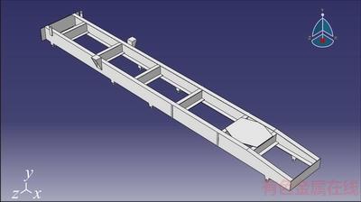
Figure 1 Heavy tactical vehicle��s chassis
The angle of camber is one of the most important kinematic factors which has significant effect in better handling of vehicles. Camber angle is the angle of wheel��s axis from the front with vertical line which is positive if it is toward inside of the car and is negative if it is toward outside of the car. This angle causes uniform pressure distribution of vehicle weight on the rubber surface. Advantage of optimum camber is stability in driving because it increases reliance surface and lowers the center of gravity.
The important note in geometric parameters of suspension system is effectiveness and geometrical relation of each parameter with the camber angle [13]. In other words, changes of camber angle affect each of the geometric parameters of the suspension and dynamic system of vehicle (Lateral forces exerted on the tire) [11]. It has been shown for step handling input that forces created in tire due to camber angles and handling can have a detrimental effect on vehicle stability [10]. Also, minimizing camber changes increases the reliance of tires and road, improves vehicle stability, improves control and ride and reduces tires wear out [17]. For this purpose, we tried to minimize camber angle changes to optimize geometric parameters of suspension system. These changes can be due to vertical displacement and twisting of vehicle��s body. Double-wishbone suspension system used in off road vehicles has been initially modeled in Adams software in this work and then the mechanism and geometry of suspension system has been optimized by evaluation of geometric parameters and angles of wheel and suspension system in different vehicle maneuvers caused by vertical displacement (roughness of the road) and vehicle��s twist in a way that stability and handling of vehicle increases in different conditions. Figure 2 shows changes of camber angle in two modes of positive and negative for the sample suspension system.
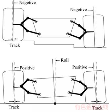
Figure 2 Changes in camber angle in terms of tire displacement
3 Geometric modeling of suspension system
Kinematic model of suspension system which is equivalent to four-arm mechanism in which the chassis is considered as interface connected to the ground is shown in Figure 3 to evaluate the effect of geometrical parameters in handling. Local x�Cy coordinate axes are selected in a way that x axis is in line with the ground (chassis) and wheel is always connected to the mechanism from C connector point. Similar to Figure 3, it is expressed for structure of suspension system with angles of ��3, ��2 and ��4 that it is measured during balance with primary angles of ��30, ��20, ��3, ��2 and ��4 relative to the positive x-axis direction. Also the length upper arm is identified by a, lower arm is identified by c, connector arm is identified by b and arm connected to the ground (chassis) is identified by d.
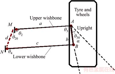
Figure 3 Suspension system and its geometric parameters
According to the definition of camber angle, changes of connector��s angle in (C) must be expressed in form of function of vertical movement (z) of point C to calculate changes of camber along the swings of wheel. Geometric coordinates of the connector point (C) in coordinate axes of the suspension system are written as follows in the form of Eq. (1) based on geometric parameters of suspension system:
 (1)
(1)
 (2)
(2)
 (3)
(3)
 (4)
(4)
 (5)
(5)
Thus, the vertical displacement of z is written in form of Eq. (6) based on xc and yc parameters:
 (6)
(6)
On the other hand, changes of camber angle (��) is expressed to be equal to (��30�C��3) based on its definition where 3�� based on geometric parameters is written as:
 (7)
(7)
where D, E and F parameters are provided as follows:
 (8)
(8)
 (9)
(9)
 (10)
(10)
Changes of camber angle (��) based on wheel vertical displacement (z) can be obtained by combining Eqs.(6) and (7) and removing 2�� parameter which will be provided in the next step as objective function of optimization.
Given the limitations of the design and layout of suspension system, a range is considered for each of the geometric parameters of suspension system. In addition to these geometric constraints, adding anti-roll bar to independent suspension systems has been shown in Ref. [15] to improve vehicle performance which can increase vehicle stability.
3.1 Anti-roll bar design
Anti-roll bar is a part of suspension system of majority of light and heavy vehicles which helps in reduction of roll of vehicle��s body during fast turns or crossing the roads with roughness. This piece connects two front wheels (left/right) through short lever arms which are connected to a coil- spring. In fact, anti-roll bar increases hardness of suspension system and its resistance to roll in turns independent from its spring rate.
Harder bar requires more power to move left and right wheels relative to each other. This factor increases the amount of power required to roll the body.
 (11)
(11)
We consider torsion equation of vehicle based on Eq. (12) in order to design anti-roll bar:
 (12)
(12)
where ms is the mass of suspension (kg); g is the gravitational acceleration (10 m/s2); h is the height of the center of gravity of the vehicle (m); �� is the roll angle; ay is the lateral acceleration of the vehicle (m/s2); T is the transverse distance of springs (m); r and f are front and rear indexes; k is the spring vertical stiffness (N/m) and ktARB is the torsional stiffness of anti-roll bar. The term inside of the bracket indicates car��s torsional stiffness in Eq. (12).
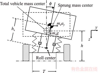
Figure 4 Schematic diagram of vehicle body while rolling
3.2 Coil-spring design
Suspension system for heavy vehicles is usually balancing column with coil-spring. Even though this suspension system has good features in the field of carrying heavy loads, it creates a type of lack of independence for axis due to connecting them. This can have negative effect on dynamic behavior of the vehicle. Thus, the objective of coil-spring design is for these two axes. Both axes will be completely independent of each other by doing this, and the dynamic behavior and vehicle stability will improve. Longitudinal spring stiffness should be converted to coil spring stiffness in order to design a coil spring. Equation (13) is used for this purpose:
 (13)
(13)
where KL is linear stiffness and LW is distance from the center of wheel to the center of torsion bar. The diagram in Figure 5 shows the changes of stiffness of coil spring for different lengths of LW.
Equation (14) can be used to determine physical characteristics of springs according to coil spring stiffness:
 (14)
(14)
where G is the coil spring modulus which is equal to 73.7 GPa; d is the diameter of the spring and L is its effective length. It is clear that d and L determine its physical properties. Figure 6 shows the relation between length and diameter.
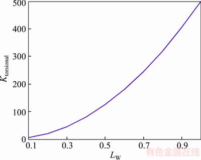
Figure 5 Spring stiffness changes due to LW
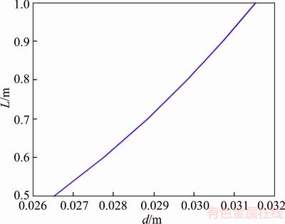
Figure 6 Changes of diameter and length of spring
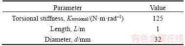
According to Figure 6, if the length of spring is equal to 1 m, the diameter of spring will be equal to 0.032 m, so the coil spring can be proposed with the following characteristics to be used in heavy vehicles as a sample. It should be noted that each of these values can be changed with respect to changes in spring torsional stiffness, length and diameter.
Table 1 Specification of proposed spring
4 Results
4.1 Anti-roll bar design
In order to evaluate the effect of adding anti-roll bar to heavy vehicle, this vehicle has been modeled in TruckSim software and has been placed under ride and ride maneuvers.
4.1.1 Ride maneuver
The vehicle performs a double redirect maneuver at a speed of 60 km/h, which compares the anti-roll bar effects on the lateral slip in Figures 7 and 8. Also, body roll angle with and without anti-roll bar are presented in Figures 9 and 10, respectively.
As observed, slipping of tires as well as the amount of body roll are reduced by adding anti-roll bar. This means that the designed anti-roll bar has improved ride behavior of the vehicle. Improved vehicle��s handling and stability mean better and higher security for the vehicle and especially the sensitive load which is being carried.
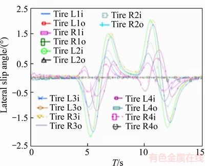
Figure 7 Lateral slip of vehicle tires without anti-roll bar
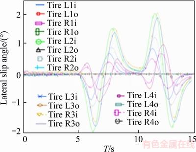
Figure 8 Lateral slip of vehicle tires with anti-roll bar
4.1.2 Vehicle��s handling maneuver
In this maneuver, the vehicle moves at the speed of 40 km/h on a rugged road (see Figure 11) and the vehicle body roll angle without and with the anti-roll bar are shown in Figures 12 and 13,respectively. As it can be observed in Figure 11, adding the designed anti-roll bar does not have negative effect on roll function of the vehicle, thus it can be seen that vehicle��s handling has not been changed along with increasing vehicle stability, and ultimately vehicle dynamic behavior has been improved.
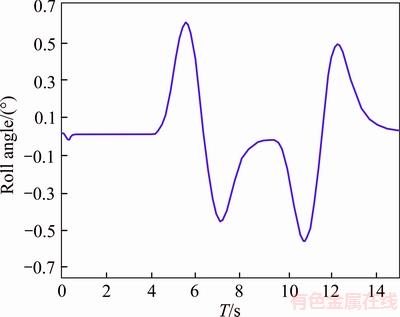
Figure 9 Body roll angle without anti-roll bar
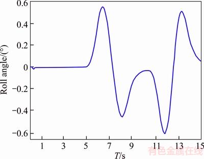
Figure 10 Body roll angle with anti-roll bar
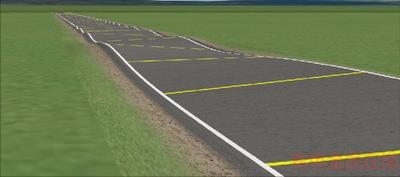
Figure 11 Photo of traveled rugged path

Figure 12 Body roll angle without anti-roll bar
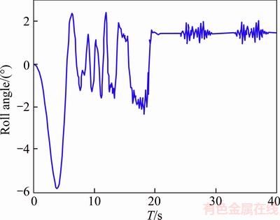
Figure 13 Body roll angle with anti-roll bar
4.2 Designing torsion bar for independent axis
Coil-spring of the 3rd and 4th axis of super heavy vehicle is modeled in Trucksim software. Coil springs have been simulated in Trucksim dynamics software in this section and then this super heavy vehicle will be tested with new springs in ride and handling maneuver.
4.2.1 Ride maneuver
The vehicle performs a double redirect maneuver at a speed of 60 km/h in this maneuver. Variations of lateral acceleration, lateral slipping and yaw angles respectively for original suspension system are shown in Figures 14(a), 15(a), 16(a) and 17(a), and those for vehicle with new suspension are presented in Figures 14(b), 15(b), 16(b) and 17(b). It is clear that the vehicle has better ride response. For example, the lateral acceleration of vehicle has reduced (up to 15%) in this maneuver by new springs which is extremely suitable and shows increased dynamic power of the vehicle.
4.2.2 Handling maneuver
The vehicle enters rugged road shown in Figure 18 at a speed of 5 km/h. Improved performance of vehicle is evident in the exercise maneuver. As shown in Figure 19, the vertical acceleration reduces up to 10% by adding anti roll bar system. This means that the designed spring has the ability to properly control vehicle during vibrations from the shown rugged road.
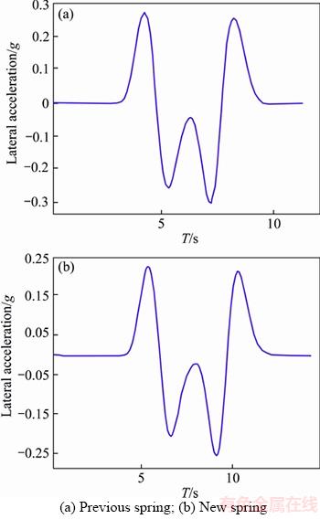
Figure 14 Lateral acceleration:
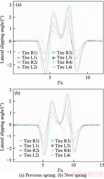
Figure 15 Lateral slipping:
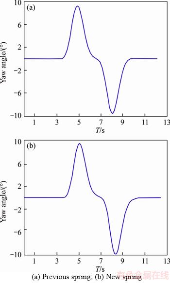
Figure 16 Yaw angle:
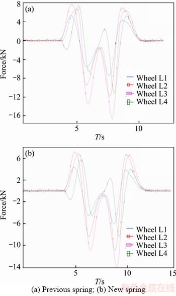
Figure 17 Lateral forces:
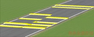
Figure 18 Severely rugged path
It can be observed that the response of camber angle changes in the optimized mode has returned to equilibrium faster, and the volatility of steady state of system is very low. Also the maximum changes of camber angle are minimized compared to non-optimized mode which leads to optimal distribution of lateral forces exerted on the tire and will increase ride and stability of the vehicle, but changes of camber angle have fluctuations in non-optimal conditions which can wear out the tire and reduce the ride of the vehicle.
It can be observed that based on diagrams of Figure 22 even though amounts of camber angle caused by displacement and twists in the positive direction of the coordinates of the vehicle are higher than negative direction, the changes in camber angle are relatively symmetric. Changes of camber angle increase by increasing angle of roll or bump height which show tendency of wheel toward outside of the vehicle and its instability but it can be observed that these camber changes are lower for optimum suspension system compared to camber changes in non-optimum suspension system which shows better stability of the vehicle with optimized double-wishbone suspension. Also with respect to decreased range of camber angles changes in optimized mode, changes of lateral force exerted on the tire are reduced and thus, tire wears out less and controlling vehicle will be easier. In this maneuver similar to turning maneuver, optimized suspension system has been able to pass the road with the least lateral deviation in addition to preserving the stability of the vehicle by adding anti-roll bar and torsion bar. Also the maximum values of lateral acceleration and lateral velocity are respectively less than 1 and 26 m/s in this mode which shows good handling and good ride of the vehicle during the maneuver. But non-optimized suspension system has fluctuations in lateral acceleration and velocity variables which can reduce occupant comfort and affect the handling of vehicle.
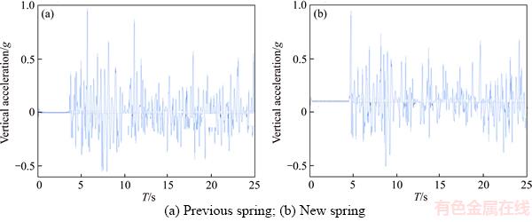
Figure 19 Vertical acceleration:
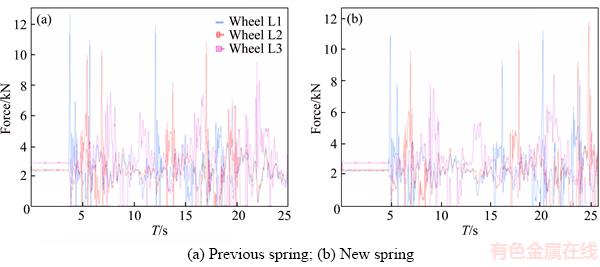
Figure 20 Vertical forces:
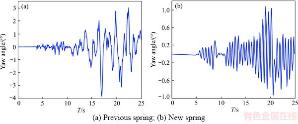
Figure 21 Yaw angle:
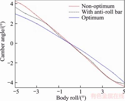
Figure 22 Changes of camber angle due to bump
5 Conclusions
Modeling of heavy vehicle��s suspension system has been done for off road vehicle in Trucksim software. We try to optimize geometric characteristics of suspension system using geometric equations governing the suspension system with the aim of minimizing camber angle changes by adding anti-roll bar and optimized torsion bar. Then sensitivity analysis and changes in suspension geometry parameters caused by inputs of bump and vehicle rolls are compared for three modes of non-optimal, optimal with anti-roll bar and optimal with torsion bar. The results show that the maximum camber angle and its range are reduced with optimizing the geometrical parameters. It can also be observed with examining the suspension system under transient conditions that camber angle changes in the steady state have fluctuations in non-optimized mode which can change the forces exerted on tire and reduce vehicle handling. But these fluctuations have fallen sharply by optimizing the suspension system and system reaches steady-state faster. In the next step, simulation of movement of vehicle during two standard maneuvers of turning and changing direction has been carried out for lateral dynamic variables of vehicle with a comprehensive modeling of off road vehicle in Trucksim software to evaluate conditions to control the direction, handling, ride and stability of vehicle. The results of the simulation show that the type of suspension system and geometric parameters of it have significant effect on handling, stability and prevention of overturning of vehicle. It can be observed that with optimization of geometric parameters of suspension system, the vehicle has been able to pass the objective direction with the lowest possible deviation and acceleration and lateral slipping while maintaining stability and improving handling and ride of the vehicle.
References
[1] CHEN S, WANG D, ZAN J. Vehicle ride comfort analysis and optimization using design of experiment [C]// IEEE, Intelligent Human-Machine Systems and Cybernetics (IHMSC), 2010 2nd International Conference on. Nanjing, 2010: 5�C12.
[2] UYS P E, ELS P S, THORESSON M. Suspension settings for optimal ride comfort of off-road vehicles travelling on roads with different roughness and speeds [J]. Journal of Terramechanics, 2007, 44: 163�C175.
[3] KHODAYARI B A, RAZAVI S. On the thermo-flow behavior in a rectangular channel with skewed circular ribs [J]. Mechanics & Industry, 2017, 18: 225�C232.
[4] MASHADI B, MAHMOODI-K M, KAKAEE A, HOSSEINI R. Vehicle path following control in the presence of driver inputs [J]. Proceedings of the Institution of Mechanical Engineers, Part K: Journal of Multi-body Dynamics, 2013, 227: 115�C132.
[5] MOKHIAMAR O, ABE M. Active wheel steering and yaw moment control combination to maximize stability as well as vehicle responsiveness during quick lane change for active vehicle handling safety [J]. Proceedings of the Institution of Mechanical Engineers, Part D: Journal of Automobile Engineering, 2002, 216: 115�C124.
[6] YANG X, WANG Z, PENG W. Coordinated control of AFS and DYC for vehicle handling and stability based on optimal guaranteed cost theory [J]. Vehicle System Dynamics, 2009, 47: 57�C79.
[7] POURASAD Y, MAHMOODI-K M, OVEISI M. Design of an optimal active stabilizer mechanism for enhancing vehicle rolling resistance [J]. Journal of Central South University, 2016, 23(5): 1142�C1151.
[8] TANG C Y, GUO L X. Research on suspension system based on genetic algorithm and neural network control [J]. The Open Mechanical Engineering Journal, 2009, 3: 72�C79.
[9] ALEKSANDER H. Rollover stability index including effects of suspension design [C]// SAE 2002 World Congress, Detroit, Michigan. 2002: 135�C139.
[10] KHOSRAVI M, MOSADDEGHI F, OVEISI M KHODAYARI-B A. Aerodynamic drag reduction of heavy vehicles using append devices by CFD analysis [J]. Journal of Central South University, 2015, 22: 4645�C4652.
[11] JAZAR R N. Vehicle dynamics theory and application [M]. Springer Science & Business Media, LLC, 2008: 234�C288.
[12] JANSEN S, OOSTEN J. Development and evaluation of vehicle simulation models for a 4WS application [J]. Vehicle System Dynamics, 1995, 24: 343�C363.
[13] SHIM T, VELUSAMY P C. Suspension design and dynamic analysis of a lightweight vehicle [J]. Int Journal of Vehicle Design, 2007, 43: 258�C280.
[14] ZAIDIE M N A, HASHIM M S M, TASYRIF M, BASHA M H, IBRAHIM I, KAMARUDDIN N S, SHAHRIMAN A B. Analysis of a front suspension system for UniART FSAE car using FEA [J]. Journal of Physics: Conference Series, 2017, 908(1): 120�C129.
[15] DIXON J C. Suspension geometry and computation [M]. John Wiley & Sons Ltd, 2009.
[16] MONTAZERI-GH M, MAHMOODI-K M. Optimized predictive energy management of plug-in hybrid electric vehicle based on traffic condition [J]. Journal of Cleaner Production, 2016, 139: 935�C948.
[17] MOKHLESPOUR I, MOSAYEBI M, POURSHAMS M. Optimization of double wishbone suspension system with variable camber angle by hydraulic mechanism [J]. World Academy of Science, Engineering and Technology, 2010, 4: 46�C61.
(Edited by FANG Jing-hua)
���ĵ���
ʹ���ۺϷ�ҡ�˺;�ȡ���ɻ����Ż�����ԽҰ������ϵͳ���ȶ���
ժҪ��������ϵͳ�Գ������ݺ���ʻ����Ҫ��Ӱ�죬����Ż���������ϵͳ����߳����ȶ��ԺͲ����Ե���Ч����֮һ���˶����ơ��ȶ���ά����ƽ˳�Ը�����ԽҰ������ϵͳ����еĻ������⡣����Trucksim������������һ����ҪӦ����ԽҰ������������ϵͳ��Ȼ�������ۺϷ�ҡ�˺;�ȡ���ɶ�����ϵͳ�ļ��β��������Ż�������˳�����ƽ˳�ԡ������Ժ��ȶ��ԡ�Trucksim �ṩ������ϵͳ�ķ�����������·��ֲڶȺ�ת��Dz�ͬ������ļ��β����ı仯�����Ƚ������Ż��ͷ��Ż������£�����ϵͳ�ڸ��ּ�ʻ�����е��Ż�Ч��������������������ϵͳ���ͺͼ��β����Գ�������������Ӱ�졣
�ؼ��ʣ�ԽҰ���������ԣ���ҡ�ˣ����ɣ�������������Trucksim
Received date: 2016-10-08; Accepted date: 2017-03-23
Corresponding author: Ilgar JAVANSHIR, PhD Candidate; E-mail: Il.javanshir@gmail.com
Abstract: Short suspension system has an indispensable effect on vehicle handling and ride, so, optimization of vehicle suspension system is one of the most effective methods, which could considerably enhance the vehicle stability and controllability. Motion control, stability maintenance and ride comfort improvement are fundamental issues in design of suspension system of off-road vehicles. In this work, a dependent suspension system mostly used in off-road vehicles is modeled using Trucksim software. Then, geometric parameters of suspension system are optimized using integrated anti-roll bar and coiling spring in a way that ride comfort, handling and stability of vehicle are improved. The simulation results of suspension system and variations of geometric parameters due to road roughness and different steering angles are presented in Trucksim and effects of optimization of suspension system during various driving maneuvers in both optimized and un-optimized conditions are compared. The simulation results indicate that the type of suspension system and geometric parameters have significant effect on vehicle performance.
