
���±��: 1004-0609(2006)07-1177-07
���¡� ��ʪ������ʱЧʱSn-Zn����Ǧ���������֯�ݻ�
Τϰ��1, 2, �Ϲ���1, �� ��2, ������2, �Ϲٶ���2, 3, ����Ӱ2
(1. �Ϻ���ѧ ���Ͽ�ѧ�빤��ѧԺ, �Ϻ� 200072;
2. �Ϻ���ѧ ������ʾ��Ӧ�ü��ɽ������ص�ʵ������������ϵͳ���ɼ�������, �Ϻ� 200072;
3. ����ΰ������˾ �Ƚ���װ�ͻ���������, San Jose, CA, USA)
ժ Ҫ��
�о�Sn-Zn�����Ͼ����º�ʪ����ʱЧ�������֯�ݻ��� ��Ϳ��Au/Ni�Ͻ��PCB��ͭ�����Ϻ���3��Sn-Zn�����ϵ�����(Sn-9Zn�Ͻ� Sn-8Zn-3Bi�Ͻ��Լ� Sn-7Zn-Al(30��10-6)�Ͻ�), Ȼ����120��, 100%���ʪ�ȡ� 2.03��105Pa�·ֱ�ʱЧ96h��192h�� �������, Znԭ�������ͽ�����ɢ, �γɸ�Zn�ಢ���� �ִ��Zn�����ڵ���OԪ�صĸ���, ʹ���-Sn��������, �Ӷ�������λ�ƿ��Ƽ���ģʽ�µĵ���ƣ��������
�ؼ���: Sn-Zn ������; ʱЧ; ʪ��; ����֯; ����ƣ��
��ͼ�����: TN406 ���ױ�ʶ��: A
Microstructure evolution of Sn-Zn based lead-free solder joints aged in humid atmosphere at high temperature
WEI Xi-cheng1, 2, JU Guo-kui1, SUN Peng2,
CHENG Zhao-nian2, SHANGGUAN Dong-kai2, 3, LIU Johan2
(1. School of Materials Science and Engineering, Shanghai University,
Shanghai 200072, China;
2. Sino-Swedish Microsystem Integration Technology (SMIT) Centre,
Shanghai University, Shanghai 200072, China;
3. Advanced Assembly and Environmental Technologies,
Flextronics Corporate Technology Group, San Jose, California,USA)
Abstract: The Sn-Zn based lead free solder appears to be an attractive alternative with a melting temperature relatively close to eutectic Sn-Pb. The addition of bismuth in Sn-Zn alloy improves its wettability and aluminum is beneficial to improve the oxidation resistance. The degradation of Sn-Zn based solder joints after exposed in the temperature and humid atmosphere with high pressure was studied. Three kinds of Sn-Zn system solders (Sn-9Zn, Sn-8Zn-3Bi and Sn-7Zn-Al (30��10-6)) were soldered on copper pad with a layer of Au/Ni and the specimens were stored in a pressure cooker for 96 or 192h. The temperature and the relative humidity in the cooker were 120�� and 100% respectively. The mechanical fatigue test was carried in a displacement-controlled mode to measure the low cycle fatigue of the joints. The results show that Zn diffuses to the surface and interface while coarsening at the same time, and the coarser Zn has weak interface with ��-Sn matrix and oxides form. High temperature and high humidity exposure decreases the mean life of Sn-Zn solder joints when they are subjected to 120�� and 100% relative humidity with 2.03��105Pa pressure for 192h.
Key words: Sn-Zn based solder; aging; humidity; microstructure; low cycle fatigue
��ȥʮ�����, ŷ�˳�̨��һϵ���µķ���, ��ʹ��������ҵ�ڷ�װ���������ٶԺ�Ǧ���ϵ�ʹ�á� ��ֹ��2006��7��, ������ŷ���г��ĵ��Ӳ�Ʒ������Ǧ���� Sn-Pb��������������Ǧ�ı���Ϊ63��37, �����¶�183�档 ������Ǧ�������������Ƚ�, ��Ǧ���ϵķ�չ�ܵ��㷺��ע�� ����, ��3%~4%Ag��Sn-Ag-Cu, �۵�ߴ�217��, ��Sn-37Pb�۵��34��, ���Sn-Ag-Cu���ϵĻ����¶ȸߴ�250�档 Ϊ����ϸߵĻ����¶�, ����������������Ҫ���õ������ԡ� ��˿��ǵ���װ�豸�ļ�����, ���跢չ���۵����Ǧ���ϡ�
Sn-Zn������������Sn-Pb����Ĺ����¶�, ������Ȼ���Ƕ�ԪSn-Pb�Ͻ��ϵ��������Ʒ[1]�� �����в��������д�����, ��, Zn�ǻ�ԭ�Խϸߵ�Ԫ��, �ڸ����¼�������, ����俹�����Ե�;��֮һ�Ǽ���ij�ֺ���Ԫ�ء� AlԪ����һ�ֿ��ܵ�ѡ�� �о�����[2-4], �ںϽ��Ʊ�������, Al����Һ̬Sn-9(Zn-5Al)�Ͻ����������������Ĥ, Al����Ĥ���γ�������Sn��Zn�Ľ�һ������, ����˺Ͻ�Ŀ��������ܡ� ʵ����֤ʵ[5-12], ��Sn-Zn�����Ͻ��м���������Bi, ������ߺ����ڵ��ӷ�װ�еĺ�������, ͬʱ���ͻ����¶ȡ� ���͵�Sn-Zn���������Ʒ(���Sn-Pb)������Ԫ�Ͻ�Sn-9Zn�Լ���Ԫ�Ͻ�Sn-Zn-Bi, Sn-Zn-Al, Sn-Zn-Ag �� Sn-Zn-Cu�ȡ� ĿǰNEC��˾�Ѿ����Ƴ�Sn-8Zn-3Bi�Ͻ�, ��Ӧ���ڸ��˵��Բ�Ʒ�ϡ� Fujitsu��˾Ҳ��2002��6�����Ƴ�Sn-Zn-Al��Ǧ����[13]�� ���й�Sn-Zn�������ڸ��¸�ʪ��������֯�����ܱ仯���о����١� �������߶�Sn-Zn��������120��, 100%�� 2.03��105Paʪ���·ֱ�ʱЧ96h��192h�������֯�ݱ估�����ƣ�����ܽ������о�, ��̽����Щ���ضԺ���ɿ��Ե�Ӱ�졣
1 ʵ��
ʵ����÷���Avantec��ѧ��˾�ṩ��Sn-9Zn�� Sn-8Zn-3Bi ��Sn-7Zn-Al(30��10-6)���ࡣ ��Ϳ��Au/Ni�Ͻ��PCB(Printed circuit board)ӡˢ��·���ͭ������, ����ƬFR-4��(������ά��)�ĺ�����мг�, ���û������γɺ��㡣 ������̲��ô�ͳ��SMT(Surface mount technology)���ա� Sn-Zn�����ϵĻ����¶����ߵ�����¶�Ϊ230��, �ܵĻ���ʱ��Ϊ6min, �۵����ϱ���ʱ��Լ1min�� Ȼ������ȡ������������, �ٽ��䱣����2.03��105Pa�� 120��, 100%���ʪ�ȵ�Hirayama PC-242 ��ѹ���зֱ�ʱЧ96h��192h�� ����������²���Instron 5548��Ӧ���еƣ�Ͳ����Ƕ��������е���ƣ�Ͳ���(LCF)�� LCFʵ����õ���λ�ƿ��Ƽ���ģʽ, ʵ�鲨��Ϊ���Dz�(R=-1), ����Ӧ���Ϊ40��m�� ����ƣ�Ͳ��Ժ�������ý��ʯ��Ƭ�и��СƬ, �Ƴɽ���ʵ�������� ��֯��ʴ����2%HCl+4%HNO3 +94%C2H5OH����Һ, �ڹ�ѧ������ɨ��羵�¹۲����ڲ�����֯�ı仯, ͨ��SEM��ɨ���о������и�Ԫ�صķֲ��� ���ú��ϺϽ����ڱ�1��
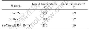
��1 �о����ú��ϺϽ�����
Table 1 Properties of solder alloys investigated
2 ʵ����
2.1 ������۽ṹ
�����������������50���˻�24h����������Ӧ��[3]�� ͼ1(a)~(c)��ʾ�ֱ�ΪSn-9Zn, Sn-8Zn-3Bi��Sn-7Zn-Al (30��10-6)������֯�� 3�ֺ����и�Zn����̬�滯ѧ�ɷֲ�ͬ���仯�� ͼ1(a)��ʾSn-9Zn�Ͻ����ϴ�, �����������֯�ֲ�����, �����������Ǧ�-Sn, ����״�Ǹ�Zn��[14]�� Sn-8Zn-3Bi���ϵ�����֯�ɰ�״�����ʹ���״����ɡ� Sn-7Zn-Al (30��10-6)������֯��Ҫ�Ǵ��״�ṹ��
2.2 ����ƣ�Ͳ���
��2�г���Sn-8Zn-3Bi��Sn-7Zn-Al (30��10-6)�ڿ���λ��(40��m)���������º����ƽ��ƣ�������� �����ʾ, Sn-8Zn-3Bi��Sn-7Zn-Al (30��10-6)�����ھ��ܸ��º�ʪ����ʱЧ��, ����ɿ��������½��� �ڸ�ѹ����ʱЧ96h������ƣ�������DZ�������32%~47%�� ͬʱ, �ڸ�ѹ����ʱЧ192h������ƣ��������Ϊ��������6%~10%, ˵������ʱЧʱ����ӳ�, ����Ŀɿ����½�����������
2.3 ���¡� ��ʪ�Ȼ������������ṹ���ݱ�
ͼ2��ͼ3��ʾΪSn-8Zn-3Bi ��Sn-7Zn-Al (30��10-6)�����ڸ�ѹ����ʱЧ������ƣ�Ͳ���ʧЧ����Ĺ�ѧ����Ƭ�� ���Է���, �ڸ�ѹ����, ����������֯�����������仯�� ʱЧ192h������������еĺ�ɫ���������Ա�ʱЧ96h��Ĵ�[CM(22]���Ҷࡣ ����, ��ͼ�л����Է���, ����������ƣ�����ƶ������ź����뺸�̵Ľ����γɲ���չ(����ǰ��һЩ�о���, �����ڲ�Ҳ�����ֹ�����), ͬʱ�ں������Ƹ�����������һЩϸ�ĺ�ɫ�����ࡣ
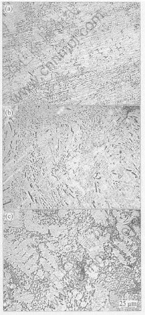
ͼ1 Sn-9Zn, Sn-8Zn-3Bi��Sn-7Zn-0.03Al�Ͻ������֯
Fig.1 Microstructures of Sn-9Zn(a),Sn-8Zn-3Bi(b) and Sn-7Zn-0.03Al(c) alloys
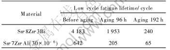
��2 Sn-Zn�������ƣ������
Table 2 Fatigue lifetime for Sn-Zn system solder joints
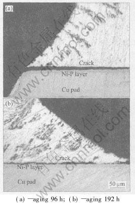
ͼ2 Sn-8Zn-3Bi����������120��, 100%���ʪ�ȸ�ѹ����ʱЧ����LCF��ʧЧ��֯
Fig.2 Failures in solder joints of Sn-8Zn-3Bi after 120��, 100% relative humidity aging in pressure cooker and LCF testing
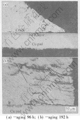
ͼ3 Sn-7Zn-Al (30��10-6)����������120��, 100%���ʪ�ȸ�ѹ����ʱЧ����LCF���ʧЧ��֯
Fig.3 Failures in solder joints of Sn-7Zn-Al (30��10-6) after 120��, 100% relative humidity aging in pressure cooker and LCF testing
�Ƚ�ͼ2(a)��3(a)����, Sn-8Zn-3Bi�����е��������Sn-7Zn-Al(30��10-6)�еĸ������ԡ� ���ź����ڸ�ѹ����ʱЧʱ����ӳ�, Sn-7Zn-Al (30��10-6)�����е����������ۼ�, ��192h��ĺ��ϻ������γ��˴�Χ�İ���ɫ����״�ࡣ
2.4 ��ɨ��������
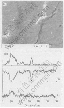
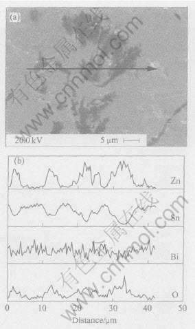
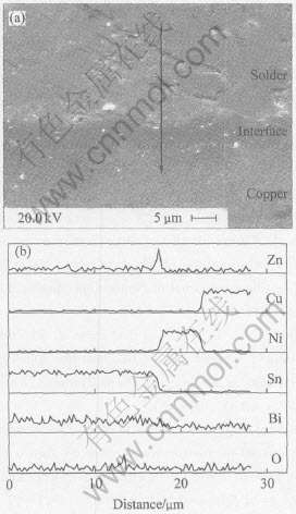
Ϊ�˷���ʧЧ���м������뺸�̽Ӵ�����������Ԫ�صķֲ����, ����SEM��ɨ��Ժ����������ƴ�����ijɷֽ����˽�һ�������� ͼ4��ͼ5�ֱ�ΪSn-9Zn�������Ϻ�Sn-8Zn-3Bi���ϵĺ����ڸ�ѹ����ʱЧ96h��ʧЧ����ĺ����������
ͼ4 Sn-9Zn������120��, 100%���ʪ��,2.03��105Pa������ʱЧ96h���SEM���EDS��ɨ��ɷֲַ�
Fig.4 SEM image of Sn-9Zn solder after exposure to 120��, 100% relative humidity, 2.03��105Pa condition for 96h(a) and composition distribution from EDS-test with line scanning on cross section of Sn-9Zn solder joint(b)
ͼ5 Sn-8Zn-3Bi������120��, 100%���ʪ��,2.03��105Pa������ʱЧ96h���SEM���EDS��ɨ��ijɷֲַ�
Fig.5 SEM image of Sn-8Zn-3Bi solder joint after exposure to 120��, 100% relative humidity, 2.03��105Pa condition for 96h(a) and composition distribution from EDS-test with line scanning on cross section of Sn-8Zn-3Bi solder joint(b)
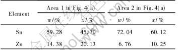
ͼ4(a)��ʾΪSn-9Zn����������Ƭ�� �ɼ������д�����������, ����ɫ����1��, ������2��, ���߶���SnԪ�غ�ZnԪ�ء� ͼ4(b)ʾ���˳ɷ���ͼ4(a)�м�ͷ����ķֲ��� ��1�����ɷ�Ϊ�϶��Zn������Sn, ����2���������෴�� �Ƚ�ͼ�����ƺͳɷֲַ�����, ���ƽ��洦��Zn�����ȹ����ɷֵ�Znƫ��, ��Snƫ��, ���롰1�����ɷֲַ�������ơ� �������, �����дֻ��ĺ������ĸ�Zn����ƣ�����Ʒ���һ�¡�
EDS��ɨ��İ붨�����(��3)����, Sn-9Zn�еġ�2������Sn 60.12%, Zn 10.25%(Ħ������), ������ɫ�ġ�1������Zn�ߴ�20.13%, �ǡ�2������Zn����2���� �����д�Χ�İ���ɫ���Ƶ��γɿ����Ǿ����ֻ����γ���ɢ��������Ľ��, �Ӷ���������������ǿ�ȡ�
��3 Sn-9Zn����������120��, 100%���ʪ��, 2.03��105PaʱЧ96h���EDS��ɨ����
Table 3 Result of EDS-test with line scanning on Sn-9Zn solder joint after exposure in 120��,100% relative humidity, 2.03��105Pa for 96h
ͼ5(a)��ʾΪSn-8Zn-3Bi������120��, 100%���ʪ��������ʱЧ96h��ĵ��ͻ�����Ƭ�� ͼ5(a)��Ҳ����һЩ��ͼ4(a)��ȫ��ͬ�ĸ���Zn�ĺ�ɫ����(ͼ5(b))�� ����ɨ��ķֲ����߿�֪, ZnԪ�غ�OԪ�صĺ�����ͬһ��ﵽ��ֵ, ����Zn��O�ijɷֲַ�������ͬ�� Ϊ�˽�һ�������ɷֲַ������ܵ�Ӱ��, �Ժ�����Cu���̽��洦�ijɷ�Ҳ�����˷�����
ͼ6 δʱЧ������Sn-8Zn-3Bi�����뺸�̽����SEM���EDS��ɨ��ijɷֲַ�
Fig.6 SEM image of interface between Sn-8Zn-3Bi solder joint and copper pad without aging(a) and composition distribution from EDS-test with line scanning on cross section(b)
ͼ6(a)��ʾΪCu�����ϵ�Sn-8Zn-3Bi���� (δʱЧ)������ƣ�ͺ���洦��SEM�� ͼ7(a)��ʾΪSn-8Zn-3Bi���㾭��ѹ��ʱЧ��, ����ƣ�ͺ���洦��SEM�� ���Կ���, ��ɫ��״��Ϊ��Zn�ࡣ ����, ͼ6(b)��ʾ��EDS�ɷֲַ����߱���, �ں�����Cu���̵ĽӴ��渽������ZnԪ�صĸ����� Duan��[15]Ҳ����, ���ػ�ʱЧ��, Znԭ����Cu�̽������ɢ����, �����ڴ˽�����δ�����ķ�ֵ��
��ͼ7(a)���Կ���, ������Ϸֲ��Ű���ɫ��״��Zn��, ��Ϊ��120��, 100%���ʪ��, 2.03��105Pa��ѹ����ʱЧ��, ��״��Zn���Ϊ��״, ͬʱҲ�γ���Zn�������ࡣ ���ݡ�Zn�����ı仯��Ӧ������������ı仯�����ֹ۵�, ����˵��ʵ���������Zn��������γɡ�
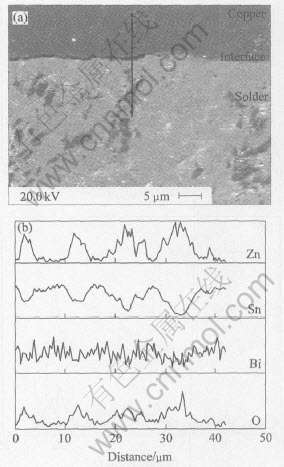
ͼ7 Sn-8Zn-3Bi������120��, 100%���ʪ��,2.03��105Pa������ʱЧ96h��Ľ���SEM��� EDS��ɨ��ijɷֲַ�
Fig.7 SEM image of interface between Sn-8Zn-3Bi solder joint and copper pad after exposure to 120��, 100% relative humidity, 2.03��105Pa condition for 96h(a) and composition distribution from EDS-analysis with line scanning on cross section between Sn-8Zn-3Bi solder joint(b)
2.5 �����︻��
ͼ4, 5��7�Ľ���������˺��������ɷֵı仯��Zn�ı仯���ƻ���һ�¡� Ϊ�˸��õ�˵���ý��, ���Ƴ�ͼ8�� ͼ8(a)��(b)��ʾ�ֱ�Ϊͼ5��ͼ7����ɨ���Zn�� O�ijɷֲַ��ĶԱȡ� ��ͼ8(a)��(b)�Ľ�����Կ���, ��������п�����ı���Լ28%, ���������и�Zn����������Ԫ�ص����ظ����� ���ͼ2~4�Ľ��, ˵��Zn�� OԪ�صĸ�����ƫ�۴ٽ��˺���������֯�����Ľ��������, �����շ����Ƶ������γ�, �Ӷ����ͺ���Ŀɿ��ԡ�
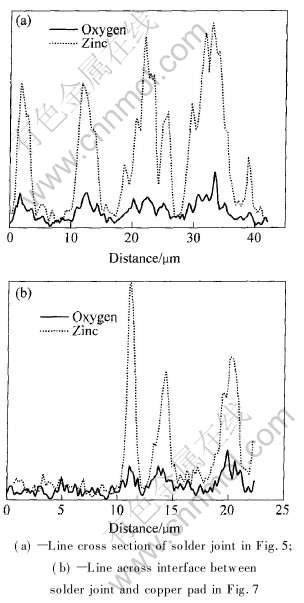
ͼ8 Sn-8Zn-3Bi���㾭120��,100%���ʪ��,2.03��105PaʱЧ96h���EDS��ɨ��ijɷֲַ�
Fig.8 Composition distribution from EDS analysis on line scanning of Sn-8Zn-3Bi solder joint after exposure of 120��, 100% relative humidity, 2.03��105Pa for 96h
3 ����
���¡� ��ѹ�����µ�ʱЧ����Ӱ��Sn-Zn����Ǧ���������֯, ����ʱЧʱ��ٽ�Zn��������Zn��� ��Zn��ٽ����������γ�, ���ͺ���ĵ���ƣ�����ܡ� �����и�Zn����ִٽ���OԪ�ص�����, ������֯������Ľ�������, �Ӷ����ͺ���Ŀɿ��ԡ�
REFERENCES
[1]Mulugeta A, Guna S. Lead-free solders in microelectrinics[J]. Materials Science and Engineering Review, 2000, 27: 95-141.
[2]Lin K L, Liu T P. High temperature oxidation of a Sn-Zn-Al solder[J]. Oxidation of Metals, 1998, 50: 255-267.
[3]����, �뼪��, �ܺ�. ��ͬǥ�϶�Ti3Al ���Ͻ�ǥ����ͷǿ�ȼ���������֯��Ӱ��[J]. �й���ɫ����ѧ��, 2005, 15(1): 24-32.
HE Peng, FENG Ji-cai, ZHOU Heng. Microstructure and strength of brazed joints of Ti3Al base alloy with different filler metals[J]. The Chinese Journal of Nonferrous Metals, 2005, 15(1): 24-32.
[4]�¾���, ���ܿ�, �ֶ���, ��. Al3Ti4B�м�Ͻ��Mg27Al20.4Zn20.2Mn�Ͻ�����֯�����ܵ�Ӱ��[J]. �й���ɫ����ѧ��, 2005, 15(3): 478-484.
CHEN Jing-yang, GUAN Shao-kang, LIN Dun-wen, et al. Effects of Al3Ti4B master alloy on microstructure and properties of Mg27Al20.4Zn20.2Mn alloys[J]. The Chinese Journal of Nonferrous Metals, 2005, 15(3): 478-484.
[5]Shiue R K, Tsay L W, Lin C L, et al. The reliability study of selected Sn-Zn based lead-free solder on Au/Ni-P/Cu substrate[J]. Microelectronics Reliability, 2003, 43(3): 453-463.
[6]Akio H, Hiroto Y, Eiichi I, et al. Joint Strength and interfacial microstructure between Sn-Ag-Cu and Sn-Zn-Bi solders and Cu substrate[J]. Science and Technology of Advanced Materials, 2004, 5(1-2): 267-276.
[7]Wang M C, Yu S P, Chang T C, et al. Kinetics of intermetallic compound formation at 91Sn-8.55Zn-0.45Al lead-free solder alloy/Cu interface[J]. Alloys & Compounds, 2004, 381(1-2): 162-167.
[8]Chang T C, Hon M H, Wang M C. Intermetallic compounds formed at the interface between Cu substrate and an Sn-9Zn-0.5Ag lead-free solder[J]. Materials Research Bulletin, 2003, 38(5): 909-916.
[9]Yu D Q, Xie H P, Wang L. Investigation of interfacial microstructure and wetting property of newly developed Sn-Zn-Cu solders with Cu substrate[J]. Alloys & Compounds, 2004, 385(1-2): 119-125.
[10]Lin K L, Liu P C, Song J M. Wetting Interactions between Pb-free Sn-Zn Series Solders and Cu, Ag Substrates[A]. ECTC ��04 Proceedings of Electronic Components and Technology[C]. IEEE, 2004. 1310-1313.
[11]Lee H T, Chen M H, Jao H M, et al. Influence of interfacial intermetallic compound on fracture behavior of solder joints[J]. Materials Science and Engineering A, 2003, 358(1-2): 134-141.
[12]Suganuma K. Low Temperature Lead-Free Soldering JIEP Project (SnZnBi etc)[A]. Proceedings of International Conference on Lead Free Electronics ��Towards implementation of the RHS Directive��[C]. Brussels, Belgium, 2003. 97-104.
[13]Yuki F, Michael G P, Kota F, et al. Lead-Free Soldering in the Japanese Electronics Industry[J]. IEEE Transactions on Components and Packaging Technologies, 2003, 26(3): 616-624.
[14]Kim K S, Yang J M, Yu C H, et al. Analysis on interfacial reactions between Sn-Zn solders and the Au/Ni electrolyti-plated Cu pad[J]. Alloys & Compounds, 2004, 379(1-2): 314-318.
[15]Duan L L, Yu D Q, Han S Q, et al. Microstructural evolution of Sn-9Zn-3Bi solder/Cu joint during long-term aging at 170��[J]. Alloys & Compounds, 2004, 381(1-2): 202-207.
(�༭�°���)
������Ŀ: �Ϻ��п�ί���ʺ���������Ŀ(045107006, 035007031); ŷ�ˡ�Flex-Eman��������Ŀ(COOP-CT-2003-507983)
�ո�����: 2005-11-28; ������: 2006-04-02
ͨѶ����: Τϰ��, ���о�Ա; �绰: 021-56331462; ����: 021-56331977; E-mail: wxc1028@staff.shu.edu.cn
