
J. Cent. South Univ. (2017) 24: 90-103
DOI: 10.1007/s11771-017-3412-1

Power loss reduction of distribution systems using BFO based optimal reconfiguration along with DG and shunt capacitor placement simultaneously in fuzzy framework
M.Mohammadi, A.Mohammadi Rozbahani, S.Bahmanyar
Department of Electrical Engineering, Borujerd Branch, Islamic Azad University, Borujerd, Iran
 Central South University Press and Springer-Verlag Berlin Heidelberg 2017
Abstract:
In distribution systems, network reconfiguration and capacitor placement are commonly used to diminish power losses and keep voltage profiles within acceptable limits. Moreover, the problem of DG allocation and sizing is great important. In this work, a combination of a fuzzy multi-objective approach and bacterial foraging optimization (BFO) as a meta-heuristic algorithm is used to solve the simultaneous reconfiguration and optimal sizing of DGs and shunt capacitors in a distribution system. Each objective is transferred into fuzzy domain using its membership function. Then, the overall fuzzy satisfaction function is formed and considered a fitness function inasmuch as the value of this function has to be maximized to gain the optimal solution. The numerical results show that the presented algorithm improves the performance much more than other meta-heuristic algorithms. Simulation results found that simultaneous reconfiguration with DG and shunt capacitors allocation (case 5) has 77.41%, 42.15%, and 56.14% improvements in power loss reduction, load balancing, and voltage profile indices, respectively in 33-bus test system. This result found 87.27%, 35.82%, and 54.34% improvements of mentioned indices respectively for 69-bus system.
Key words:
1 Introduction
The conventional techniques used in distribution systems for power loss reduction, voltage profile improvement are network reconfiguration, capacitor placement, distributed generations (DGs) placement, reconfiguration with DGs placement, and reconfiguration with capacitor placement. Some researches as reviewed bellow only have analyzed the reconfiguration process to improve distribution system indices [1-4].
Authors of Ref. [1] have applied the multi-objective invasive weed optimization (IWO) technique to optimal network reconfiguration in radial distribution systems. Optimal network reconfiguration is one of the techniques utilized by distribution operators in normal and emergency condition for optimal operation of the distribution system. In distribution networks there are two kinds of switches: sectionalizing switches (normally closed) and ties witches (normally opened). The network reconfiguration problem is identical to the problem of selection of an appropriate tie switch for each loop so that the objective function could be minimized. The main objective of reconfiguration is to reduce losses, increase stability and reliability, improve voltage profile (VP), and relieve overload in the distribution network. Gravitational search algorithm (GSA) was implemented for minimization of loss reduction and to improve voltage deviation [2]. In Ref. [3], the distribution system reconfiguration for loss minimization using modified bacterial foraging optimization (MBFO) algorithm has been presented and discussed. In Ref. [4], a novel power system reconfiguration for a distribution system with minimum load balancing index using bacterial foraging optimization algorithm (BFO) was analyzed and investigated.
Moreover, the problem of DG allocation and sizing is great important. Installing DG units at optimal placement and sizing will decrease the system losses and improve the voltage level of system. Others have combined the reconfiguration process with DGs placement for this purpose [5-11]. To achieve the benefits of DG units, the selection of optimal locations and capacity is becoming the major problem [5]. JOHN et al [6] used mixed integer linear programming (MILP) model of reconfiguration of distribution systems considering the presence of distributed generation. CHOI and KIM [7] adopted genetic algorithm to the problem of network reconfiguration with dispersed generations. In Ref. [8] the authors applied particle swarm optimization for distribution feeder reconfiguration considering DGs. In Ref. [9], a Tabu search algorithm has been used to the feeder reconfiguration problem with dispatch-able distributed generators. The simultaneous reconfiguration and placing DG with proper sizing has been shown in Ref. [10] using harmony search algorithm (HSA). In Ref. [11], the artificial bee colony algorithm based on onlooker and scout bee��s was used for distribution feeder reconfiguration with presence of distributed generation.
Papers reported [12-16] have been focused on the distribution system quality improvement using simultaneously implementation of reconfiguration and capacitor placement. The shunt capacitors can be considered redundant lines in the system inasmuch as reducing the reactive current leads to enhanced load-carrying capability of the lines, as discussed in Ref. [12]. ESMAEILIAN and FADAEINEDJAD [13] applied a binary gravitational search algorithm (BGSA) to solve the fuzzy multi-objective problem of efficiency improvement of distribution system using network reconfiguration and capacitor allocation. PEPONIS et al [14] discussed a methodology in which the branch exchange technique is utilized for the reconfiguration, and the capacitor allocation problem is solved through dynamic programming. The energy loss reduction is estimated by the summation of power loss reductions for all different network loading conditions over the study period. These loading conditions are represented by typical daily load curves. However, the daily load curves are not considered in the problem formulation, and so better quality solutions may not be achieved. JIANG et al [15] proposed an algorithm for reconfiguration and capacitor control in order to reduce active power losses in distribution systems. The reconfiguration is performed via simulated annealing (SA), and a discrete optimization algorithm, based on load flow analysis, is used to find the capacitor control. In another research, the optimal reconfiguration and capacitor allocation in balanced and unbalanced systems using the hybrid Shuffled frog leaping algorithm in the fuzzy framework with aim of minimizing the total network real power losses and buses voltage violation, and balancing the load in the feeders was analyzed in Ref.[16].
The new idea in this work considers the two policies of DGs and capacitor placement along with reconfiguration. Also the multi objective consideration of this problem is another idea of this research. The network reconfiguration problem, together with the consideration of the effects of the DGs and shunt capacitors consists of two sections for decision variables. The first section relates to tie and sectionalizing switch numbers and has a discrete nature. The second section is the DGs capacity and also capacitor capacity which has a continuous nature and this issue increases the complexity of the optimization problem. Consequently, this problem is a nonlinear complex multi-objective optimization.
On the other hand, due to significant computational time reduction and faster convergence of BFO in comparison with other intelligent optimization approachs such as genetic algorithm (GA) and particle swarm optimization (PSO) algorithm, the BFO is implemented.
When there are different objectives to be satisfied simultaneously, a comparison is required to get the best solution. Since different terms of the multi objective function are in various ranges, all the values are normalized in the same range to avoid the convergence problem. So, the fuzzy approach for this purpose is utilized.
2 Multi-objective formulation
2.1 Power loss reduction
The first objective function of the problem is formulated so as to get a maximum power loss reduction in distributed system which is the sum of power loss reduction due to reconfiguration as well as connection of DGs and shunt capacitors, which is subject to the voltage, current and power flow constraints as
 (1)
(1)
where  is total real power loss reduction due to reconfiguration;
  is total real power loss reduction due to connection of DG;
  is total real power loss reduction due to connection of shunt capacitor.
2.2 Power loss using network reconfiguration
The use of reconfiguration in a radial distribution network is to identify a best configuration which can give a minimum power loss without violating the operation constraints. The operating constraints here are voltage limits, current capacity of the feeder feeding each and every bus always. The power loss of a line section connecting buses between i and i+1 after the reconfiguration of network is calculated as
 (2)
(2)
Total power loss in all the feeder sections, P��T,Loss, can be found by adding up the losses in all line sections of the network which expressed as
 (3)
(3)
The difference of power loss before and after reconfiguration which is the net power loss reduction,  is given as [15]
 (4)
(4)
where i is the bus number and N is the total number of buses as shown in Fig. 1.
2.3 Power loss using DG installation
By connecting a distribution generation, units in a radial distribution system at optimal locations give several advantages like reducing line losses, improving voltage profile, reducing peak demand, reduction in overloading of distribution lines, reduction in environmental pollution. The power loss when a DG is installed at an arbitrary location in the network is calculated as [10]
 (5)
(5)
Net power loss reduction, , in the system is the difference in power loss between before and after connecting a DG unit.
 (6)
(6)
The positive sign of  shows that the system loss is reduced with the installation of DG, whereas the negative sign of indicates that DG causes the system loss to increase. G is distance from source to the DG location and L is total length of the feeder from source to bus i.
2.4 Power loss using capacitor installation
On the other hand, the shunt capacitors are applied for reactive power compensation locally to reduce the power loss and sustain the voltage profile within an acceptable operating limit. The shunt capacitors can be considered redundant lines in the system inasmuch as reducing the reactive current leads to enhanced load-carrying capability of the lines. Connecting shunt capacitors in a radial distribution system at optimal locations gives several advantages like reducing line losses, improving voltage profile, enhancing load- carrying capability of the lines. The power loss when a capacitor is installed at an arbitrary location in the network is calculated as
 (7)
(7)
Net power loss reduction,, in the system is the difference in power loss between before and after connecting a DG unit.
 (8)
(8)
The positive sign of shows that the system loss are reduced with the installation of capacitor, whereas the negative sign of indicates that capacitor causes the system loss to increase.
2.5 Minimum voltage deviation
For the purpose of minimizing the bus voltage deviation, the improvement in the VP is reflected as shown by VP index:
 (9)
(9)
where Vmax is the high voltage limit; Vmin is the low voltage limit; V(i) is the bus i voltage.
2.6 Improving load balancing index (LBI)
The third term of the objective function is considered for the LB index of the lines in the feeders. For the purpose of load balancing, first an appropriate parameter is defined, indicating what portion of the branches has been loaded. This portion is defined as the line usage index for the ith branch, calculated as follows [18]:
 (10)
(10)
where LBI is the load balancing index; Imax is the maximum current capacity of the ith branch of the system. For all the branches of the system LBI index is calculated as follows.
 (11)
(11)
LBI=Var(Y) (12)
where Var represents the variance operation. However,the smaller value of the LBI index indicates that the load balancing has been conducted more efficiently.

Fig. 1 A single line diagram of a radial distribution (i) feeder
3 Constraints
3.1
Power flow equations
Power flow equations in the network must be satisfied throughout the optimization process. These equations can be mathematically expressed as follows:
 (13)
(13)
 (14)
(14)
where Vi and ��i are voltage and voltage angle of bus i, respectively; Pi and Qi are the generated active and reactive power at bus i, respectively; PLi and QLi are the load active and reactive power. In addition to the equality constraint, this problem has some inequality constraints. The inequality constraints are presented below:
3.2 DG penetration level limitation
DG penetration level limitation can be written as follows:
 (15)
(15)
where �� is the penetration level of the DG that is a number between 1 and 0. According to this limitation, the total installed distributed generation capacity should be less than the sum of the active load demand.
3.3 Capacitor penetration level limitation
Capacitor penetration level limitation can be written as follows:
 (16)
(16)
where �� is the penetration level of the shunt capacitors that is a number between 1 and 0. According to this limitation, the total installed reactive capacity by shunt capacitor should be less than the sum of the reactive load demand.
3.4 Shunt capacitor constraints
Shunt capacitors that are available in the industry is shown by Eq. (17). L is an integer number and Q0 is the smallest available capacitor size.
 (17)
(17)
3.5 Active and reactive power generation constraint of distributed generator and shunt capacitors
 (18)
(18)
3.6 Bus voltage limitation
Bus voltage limitation can be written as follows:
 (19)
(19)
Bus voltage magnitudes of the distribution system should be kept at acceptable levels.
3.7 Thermal limit
Thermal limit can be written as follows:
 (20)
(20)
where Sij is the apparent power flow at distribution system lines between bus i and j.
3.8 Radiality constraint
In this work bus incidence matrix  is proposed for checking the radiality of trial solutions [8]. Matrix has one row for each branch and one column for each node with an entry aij in row i and column j according to the following rules:
 (21)
(21)
In network calculation, a reference node must be chosen. The column corresponding to the reference node is omitted from and the resultant matrix is a square branch-to-node matrix and expressed by A. If the determinant of A is equal to 1 or -1, then the system is radial; Else, if the determinant of A is equal to zero, this means that either the system is not radial, or groups of loads are disconnected from the service.
4 Fuzzy membership functions
When there are different objectives to be satisfied simultaneously, a comparison is required to get the best solution. Since different terms of the multi objective function are in various ranges, all the values are normalized in the same range to avoid the convergence problem [19]. Each variable has a membership function (��) that determines the rank and effectiveness of its variable as follows.
4.1
Membership function for real sectional loss
According to Eq. (1), a sectional ohmic loss in any branch of the feeder is not allowed to increase during reconfiguration, distributed generation and capacitor placement and sizing scenario. To guarantee the achievement of this, a new exponential membership function ��p given in Ref. [20] is proposed as shown in Fig. 2.
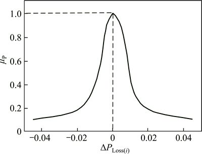
Fig. 2 Proposed membership function ��p for sectional ohmic power loss [20]
 (22)
(22)
where wp is the weighting factor whose value is determined from experiences and ��PT,loss is the difference between total active power loss before and after optimization. In the definition of this membership function, the bus with low membership value is the bus at which the loss significantly decreases. A bus of small loss decreasing is given a high membership function value.
4.2 Membership function for bus voltage
For the voltage sensitivity, the same membership function for voltage given in Ref. [21] is chosen. This membership function is illustrated as given in Fig. 3, and is defined as follows:
 (23)
(23)
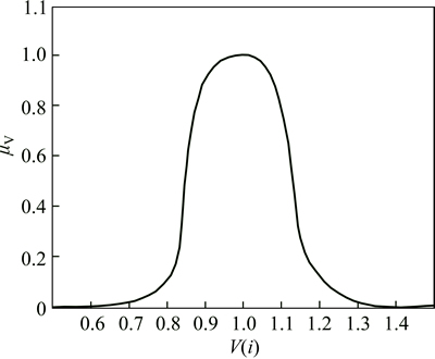
Fig. 3 Membership function ��v for voltage sensitivity [21]
where wv is the weighting factor for voltage membership function.
4.3 Membership function for load balancing index
The index of XBi for load balancing is defined as [16]
 (24)
(24)
where  is the load balancing before network reconfiguration and capacitor placement, calculated in initial power flow for each case study, and
  is the load balancing of the ith radial system after reconfiguration and capacitor placement.
Membership function of feeder load balancing index as shown in Fig. 4 is formulated as follows:
 (25)
(25)
Where  and
and  are the lower and upper limits of
  , respectively. To determine the and, the best and the worst system configuration is considered for feeder load balancing. andare considered 0.1 and 0.5, respectively.

Fig. 4 Membership function for load balancing index
4.4 Degree of overall fuzzy satisfaction
The idea of multi-objective function is proposed for the following purposes:
1) Finding the best and most compatible system configuration satisfying every objective.
2) Satisfying operational limits such as voltage and current constraints and also preventing load islanding.
In this work, a new operator named ��max-geometric mean�� is utilized to determine the degree of overall fuzzy satisfaction in the proposed method. This operator is expressed as follows [22]:
 (26)
(26)
where ��Oi in the BFO is considered the fitness function, maximized during the optimization process to obtain the best compatible configuration. This operator has several advantages. For instance, if any membership function of each objective reaches the value of zero, ��Oi is assigned a value of zero.
Furthermore, this function provides correct information about how to make this algorithm achieve an ideal state, namely a value of 1.
5 Bacterial foraging optimization algorithm
The BFO algorithm was first presented by PASSINO in 2002 [23]. The idea in this optimizing technique is adopted from biological and physical living behavior of E.coli bacteria existing in human intestine. E.coli bacterium can decide to move in two different ways with regard to its environment. The rotation of flagella shows the type of the movement. A bacterium can swim (swim for a short time) or tumble, and shift between these two positions during its life-span. Figure 5 shows the bacterium movement [23].
The flowchart of BFO process is presented in Fig. 6. This algorithm is introduced in this section [23].
Suppose that we need to find the minimum of a function J(��), �ȡ�RP; When we don��t have a deterministic description of J(��) or gradient, this problem becomes non gradient optimization problem, where the ideas from bacteria foraging can be used. Suppose that �� is the position of the bacteria and J(��) represents the environment conditions, with J(��)<0, J(��)=0 and J(��)>0 representing that the bacteria location is a nutrient rich, neutral, or noxious environment, respectively. The chemotaxis is a foraging behavior where bacterium attempts to increase the nutrient concentration, avoid noxious substances and search for ways out of neutral media by random walk.

Fig. 5 Schematic diagram of E.coli cell movement behavior

Fig. 6 BFO flowchart
Then, we can define chemotactic step j as tumble followed by a number or a run, a reproductive step k as the selection of the fittest in the population and its splitting, and an elimination-dispersal event l as the selection of random individuals and its relocation on new random positions. Then, P(j, k, l)=��i(j, k, l)�Ui=1, 2, ��, S are the positions of each number of the S bacterium population at the jth chemotactic step, the kth reproductive step and lth elimination and dispersion event. Then J(i, j, k, l) is the location cost of the ith bacterium ��i(j, k, l)��RP and Nc is bacteria��s life time in the chemotactic steps. The bacterium moves following (l) where C(i) is size of the step at the direction of ��(i). If in ��i(j+1, k, l), the value of J(i, j+1, k, l) is less than that in ��i(j, k, l), then a new step is taken in the same direction until a maximum of Ns, making this cycle a chemotactic step.
 (27)
(27)
During its movement, the bacterium communicates one another using chemical substances known as attractants and repellents, which deforms the search space, making those locations where more individuals are located more attractive, but at the same time, avoid that bacteria get on top of one another. To calculate this effect Eq. (28) is used, where mar is the magnitude of the attractant/repellent, wat and wre are the width of the attractant and repellent, respectively.

 (28)
(28)
After Nc chemotactic steps, a reproduction step is taken. For the reproduction, the healthiest bacteria are split and the others are eliminated, maintaining a constant population. The individuals to be reproduced are selected by using a health metric which is the cumulative sum of the cost value on each position visited by the bacterium. After Nre reproduction steps, a dispersion and elimination event is made, where each bacterium is subject to relocation with a probability Ped. After Ned dispersion and elimination, the algorithm ends. The population size s is restricted to an even number. So, the population can be easily kept constant.
6 Proposed fuzzy-BFO method
The distribution network reconfiguration problem, together with the consideration of the effects of the DGs and shunt capacitor banks consists of three sections for decision variables. The first section relates to tie and sectionalizing switch numbers and has a discrete nature. The second section is the shunt capacitor banks�� capacity which has a discrete nature. The last section is the DGs capacity, which has a continuous nature and this issue increases the complexity of the optimization problem. Consequently, this problem is a nonlinear complex multi-objective optimization.
In this section, the proposed fuzzy-BFO approach has been used for reconfiguration and optimal sizing of shunt capacitors and DG units in distribution system.
An optimal feeder topology can be represented as
S1=[tie switches1, DG1, Shunt capacitor1]
In the S1 vector, DG1 is a matrix with two columns as follows:
DG1=[sizeDG1 locationDG1]
And Shunt capacitor is a 1��2 matrix as follows:
Shunt capacitor1=[sizeShunt capacitor1 location Shunt capacitor1]
where  and
and  are the initial proposed capacity and bus location for the DG unit, respectively; and
  and
and  are the initial capacity and bus candidate to install the shunt capacitor, respectively. By updating the BFO algorithm, the second, third, and the ith solution vectors are generated with the new proposed tie switches, DG, and shunt capacitor size and location as follows:
Si=[tie switchesi, DGi, Shunt capacitori]
For the ith solution, a power flow program is carried out, the fuzzy membership values, and the fitness of objective function are evaluated and compared with the previous solution and therefore the better solution has been selected and replaced. The proposed method is summarized in the following steps:
Step 1) Read data of distribution system (bus, load, branch, sectionalizing, number of tie switches, etc.), initialize the BFO parameters and run the power flow program [24].
Step 2) Generate a solution vector as ��S�� by offering the tie switches, DG, and shunt capacitor sizes and locations in the network without violating the constraints. Run the power flow program; evaluate the fuzzy membership values (��) for each objective function. Calculate the fitness of fuzzy objective function according to Eq. (17). Save the solution as the best solution.
Step 3) Update the BFO swarm parameters values using Eqs. (20) and (21). Generate a new solution by updating BFO, and compare the fitness value of the new solution with the best solution. If the new generated solution has a better fitness value than the best solution, save it as the best solution.
Step 4) Check the number of iterations, and if the number of iterations does not exceed the specified value, repeat step 3).
Stop 5) Defuzzification of the best solution and print the result.
Step 6) Stop.
7 Simulation and numerical results
Based on the proposed methodology, a program has been written in MATLAB software. In order to evaluate the performance of the proposed approach, the program has been applied on two test systems at the nominal load. In this work, five different cases have been considered to analyze the effectiveness of the proposed approach.
Case 1: the base system without reconfiguration, DG, and shunt capacitors.
Case 2: the base system only with reconfiguration.
Case 3: the base system with reconfiguration and DG allocation.
Case 4: the base system with reconfiguration and capacitor allocation.
Case 5: the base system with simultaneous reconfiguration, DG, and capacitor allocation.
The test systems that are used in this study have some tie lines. It is considered that the total number of tie switches is maintained after reconfiguration. In other words, whenever one of the tie switches is closed, one of the closed switches will be opened and the network remains in radial structure simultaneously feeding all loads. The first test system as shown in Fig. 7 is a 33-bus distribution system with a total load of 3.7 MW and 2.3 MVar having 5 ties and 32 sectionalizing switches [25]. The power flow is performed using Sbase=100 MVar and Vbase=12.66 kV.
The second distribution test system as shown in Fig. 8 is a 69-bus distribution system with a total load of 3.8 MW and 2.7 MVar. The system consists of 74 branches as well as five tie switches, while the load is assumed to be constant [26].
The results of the proposed approach for 33-bus test system are presented in Table 1 for the five tested cases. It is observed from Table 1 that base case power loss in the system is 202.5 kW, which is reduced to 132.69, 72.26, 101.08 and 45.65 kW for cases 2 to 5 respectively. VP index is calculated as 1.71, 1.47, 1.31, 1.12, and 0.75
and LB index is obtained as 67.71, 58.42, 45.24, 43.57, and 39.17 for cases 1 to 5, respectively. Also, Table 1 shows the optimal location and size for DGs and shunt capacitors for the cases 3 to 5. By comparing the improvements obtained for cases 2 to 5 with the base case (case 1), it is found that simultaneous reconfiguration with DG and shunt capacitors allocation (case 5) has 77.41%, 42.15%, and 56.14% improvements in Ploss, LB, and VP indices, respectively. Also, as presented in Table 2 the results of BFO method (without fuzzy system) for 33-bus test system shows that the power loss is 138.87, 75.12, 103.58, and 51.24 kW, VP index is 1.49, 1.38, 1.17, and 0.82, and LB index is 58.44, 44.32, 43.56, and 39.31 for cases 2 to 5, respectively. The obtained results show that the performance of fuzzy-BFO approach is better as compared to the BFO (without fuzzy system) for 33-bus test system.
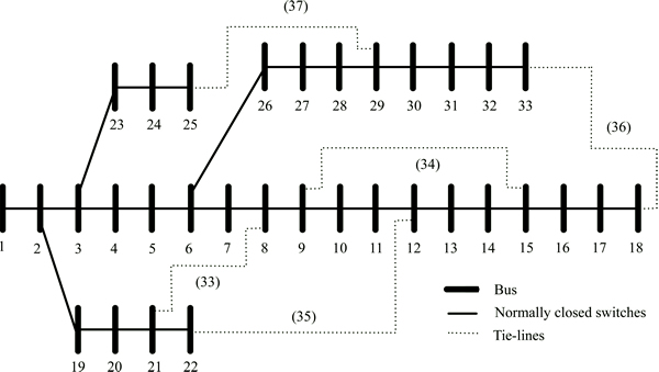
Fig. 7 IEEE 33-bus test distribution system with five tie switches

Fig. 8 IEEE 69-bus test distribution system with five tie switches
A comparison among reconfiguration process along with only DG placement (case 3), only capacitor placement (case 4) and with both simultaneous DG and shunt capacitor placement (case 5) for 33-bus test system is shown in Fig. 9.
Figure 9 clears that the effect of simultaneous reconfiguration and DG placement is more significant as compared to simultaneous reconfiguration and shunt capacitor placement on power loss reduction. However, it is demonstrated that simultaneous reconfiguration, DG and shunt capacitor placement are the most effective way to improve the power system indices.
Case 5 (at nominal load) is simulated using fuzzy-genetic algorithm (GA) and fuzzy-particle swarm optimization (PSO) and compared with the results obtained by fuzzy-BFO method. A personal computer with 4 GB RAM and 2.4 GHz CPU is used to execute
algorithms. All parameters of each algorithm are tuned for achieving the best solution. The results of different methods on both test systems are presented in Table 3 for the case 5. From Table 3, for the 33-bus test system PLoss is calculated as 51.12, 47.86, and 45.65 kW, VP is obtained as 0.83, 0.79, and 0.75 and LB is 45.43, 43.57, and 39.17 using fuzzy-GA, fuzzy-PSO, and fuzzy-BFO approaches, respectively.
Table 1 Optimization results of 33-bus test system

Table 2 Improvement results of objective functions of 33-bus test system


Fig. 9 Percentage improvements in PLoss, LB and VP indexes for cases 3-5 in 33-bus distribution system
To evaluate the proposed method, this algorithm is compared with other heuristic and intelligent algorithms in Tables 4-6. The first row shows the initial structure of the network with its power loss (i.e. 202.5 kW). By comparing the proposed algorithm (the last row) with other methods, the speed and accuracy of fuzzy based
BFO (FBFO) are confirmed.
Table 3 Comparison of simulation results by different methods for case 5 in 33-bus system

Table 4 Comparison of different methods for case 2 (only reconfiguration) in 33-bus system

Table 5 Comparison of different methods for case 3 (reconfiguration and DG allocation) in 33-bus system
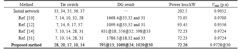
Table 6 Comparison of different methods for case 4 (reconfiguration and capacitor allocation) in 33bus system
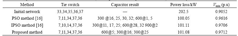
Figure 10 shows the percentage improvements in PLoss, LB, and VP indices using the fuzzy-GA, fuzzy- PSO, and fuzzy-BFO approaches for case 5 compared with the base case (case 1) in 33-bus test system.
It can be seen from Fig.10 that among three terms PLoss, LB, and VP, the improvement in PLoss is the most significant for all three fuzzy-GA, fuzzy-PSO, and fuzzy-BFO approaches. This means that reconfigurationwith simultaneous placement of DGs and shunt capacitor banks has a greater impact on loss reduction as compared to VP or LB improvement.

Fig. 10 Percentage improvements in PLoss, LB and VP indexes using fuzzy-GA, fuzzy-PSO, and fuzzy-BFO methods in 33-bus distribution system
The results of the proposed approach for 69-bus test system are presented in Table 7 for the five tested cases. It is observed from Table 1 that base case power loss in the system is 226.92 kW, which is reduced to 97.34, 33.86, 33.63 and 28.87 kW for cases 2 to 5 respectively. VP index is calculated as 1.84, 1.59, 1.44, 1.23, and 0.84 and LB index is obtained as 77.26, 68.83, 55.34, 53.83 and 49.58 for cases 1 to 5, respectively. Also, Table 7 shows the optimal location and size for DGs and shunt capacitors for the cases 3 to 5.
By comparing the improvements obtained for cases 2 to 5 with the base case (case 1), it is found that simultaneous reconfiguration with DG and shunt capacitors allocation (case 5) has 87.27%, 35.82%, and 54.34% improvements in power loss reduction, load balancing, and voltage profile indices, respectively. Also, as presented in Table 8 the results of BFO method (without fuzzy system) for 69-bus test system shows that the power loss is 98.12, 36.17, 33.79 and 30.65 kW, VP index is 1.62, 1.41, 1.27, and 0.86, and LB index is 69.33, 55.87, 54.12, and 50.34 for cases 2 to 5, respectively.
Table 7 Optimization results of 69-bus test system
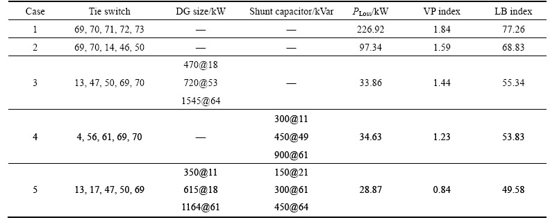
Table 8 Improvement results of objective functions of 69-bus test system
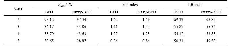
The obtained results show that the performance of fuzzy-BFO, (FBFO) approach is better as compared to the BFO (without fuzzy system) for 69-bus test system.
Figure 11 represents s comparison among reconfiguration processes along with only DG placement (case 3), only capacitor placement (case 4) and with both simultaneous DG and shunt capacitor placement (case 5) in 69-bus test system.

Fig. 11 Percentage improvements in PLoss, LB and VP indexes for cases 3-5 in 69-bus distribution system
Figure 11 clears that the influence of considering reconfiguration and DG allocation simultaneously is more significant as compared to simultaneous reconfiguration and shunt capacitor placement on power loss reduction. However, it is concluded that reconfiguration with DGs and shunt capacitor banks optimization as simultaneous is the most effective way to improve the power system indices.
The results of different methods on both test systems are presented in Table 9 for the case 5. From Table 9, for the 69-bus test system PLoss is calculated as 32.17, 31.23, and 28.87 kW, VP is obtained as 0.93, 0.87, and 0.84 and LB is 53.18, 51.32, and 49.58 by fuzzy-GA, fuzzy-PSO, and fuzzy-BFO approaches, respectively.
To evaluate the proposed method, this algorithm is compared with other heuristic and intelligent algorithms in Tables 10-12. The first row shows the initial structure of the network with its power loss (i.e. 226.92 kW). By comparing the proposed algorithm (the last row) with other methods, the speed and accuracy of FBFO are confirmed.
Figure 12 shows the percentage improvements in PLoss, LB, and VP indices using the fuzzy-GA, fuzzy-PSO, and fuzzy-BFO approaches for case 5 as compared to the base case (case 1) in 69-bus distribution test system.
As seen in Fig. 12 it is obvious that the reconfiguration with simultaneous placement of DGs and shunt capacitor banks has a greater impact on loss reduction as compared to VP or LB improvement.
Table 9 Comparison of simulation results by different methods for case 5 in 69-bus system
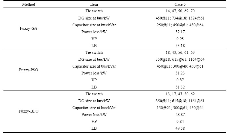
Table 10 Comparison of different methods for case 2 (only reconfiguration) in 69-bus system
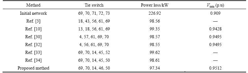
Table 11 Comparison of different methods for case 3 (reconfiguration and DG allocation) in 69-bus system
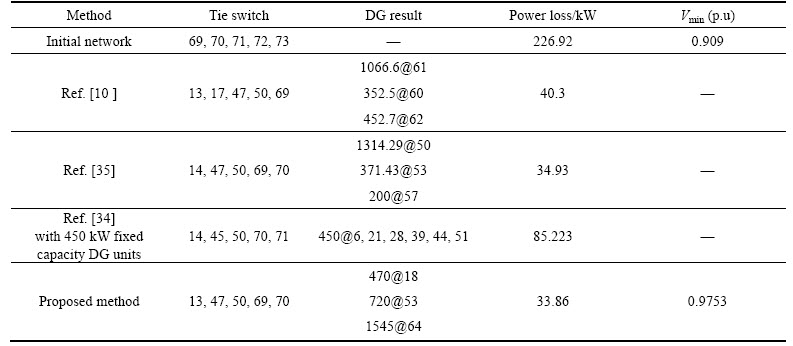
Table 12 Comparison of different methods for case 4 (reconfiguration and capacitor allocation) in 69-bus system
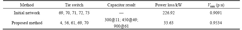
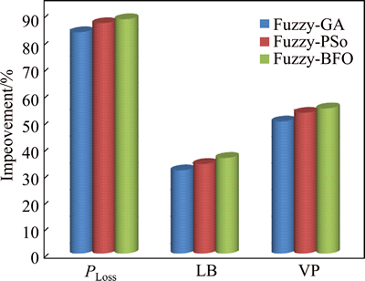
Fig. 12 Percentage improvements in Ploss, LB and VP indexes using fuzzy-GA, fuzzy-PSO, and fuzzy-BFO methods in 69-bus distribution system
8 Conclusions
1) A fuzzy-BFO-based algorithm has been presented for simultaneous reconfiguration and allocation of DGs and shunt capacitor banks.
2) The proposed approach is employed to mitigate the power loss, VP improvement, and equalizing the feeder LB in distribution system.
3) To test the effectiveness of the proposed approach, five different cases have been tested on 33-bus and 69-bus test systems.
4) The obtained results are compared with the fuzzy-GA and fuzzy-PSO and found to be better than the above-mentioned approaches because of the lowest fitness. Also, the performance of fuzzy-BFO is better as compared to the BFO method.
5) Simulation results found that simultaneous reconfiguration with DG and shunt capacitors allocation (case 5) has 77.41%, 42.15%, and 56.14% improvements in power loss reduction, load balancing, and voltage profile indices, respectively in 33-bus test system. This result found 87.27%, 35.82%, and 54.34% improvements of mentioned indices respectively for 69-bus system.
References
[1] SUDHA RANI D, SUBRAHMANYAM N, SYDULU M. Multi-objective invasive weed optimization��An application to optimal network reconfiguration in radial distribution systems [J]. International Journal of Electrical Power and Energy Systems, 2015, 73: 932-942.
[2] SHUAIB Y M, KALAVATHI M S, ASIR RAJAN C C. Optimal reconfiguration in radial distribution system using gravitational search algorithm [J]. Electric Power Components and System, 2014, 42: 703-715.
[3] NAVEEN S, SATHISH KUMAR K, RAJALAKSHMI K. Distribution system reconfiguration for loss minimization using modified bacterial foraging optimization algorithm [J]. International Journal of Electrical Power and Energy Systems, 2015, 69: 90-97.
[4] SATHISH KUMAR K, JAYABARATHIA T. Novel power system reconfiguration for a distribution system with minimum load balancing index using bacterial foraging optimization algorithm [J]. Frontiers Energy, 2012, 6(3): 260-265.
[5] BAGHERI TOLABI H, MOHD HASAN A, RIZWAN M. Simultaneous reconfiguration, optimal placement of dstatcom, and photovoltaic array in a distribution system based on fuzzy-ACO approach [J]. IEEE Transactions on Sustainable Energy, 2015, 6(1): 210-218.
[6] JOHN F F, MARCOS J R, MARINA L, RUB N R. A mixed-integer LP model for the reconfiguration of radial electric distribution systems considering distributed generation [J]. Electric Power System Research, 2013, 97: 51-60.
[7] CHOI J H, KIM J C. Network reconfiguration at the power distribution system with dispersed generations for loss reduction [C]// Power Engineering Society Winter Meeting IEEE. Singapore, 2000.
[8] OLAMAEI J, NIKNAM T, GHAREHPETIAN G. Application of particle swarm optimization for distribution feeder reconfiguration considering distributed generators [J]. Applied Mathematics and Computing, 2008, 201(1, 2): 575-586.
[9] RUGTHAICHAROENCHEEP N, SIRISUMRANNUKUL S. Feeder reconfiguration with dispatch able distributed generators in distribution system by Tabu Search [C]// Universities Power Engineering Conference (UPEC), Proceedings of the 44th International. Jlasgow, UK, 2009.
[10] RAO R S, RAVINDRA K, SATISH K, NARASIMHAM S V L. Power loss minimization distribution system using network reconfiguration in the presence of distributed generation [J]. IEEE Transaction Power System, 2013, 28(1): 317-325.
[11] MURTHY G V K, SIVANAGARAJU, SATYANARAYANA S, HANUMANTHA RAO B. Artificial bee colony algorithm for distribution feeder reconfiguration with distributed generation [J]. IJESET: International Journal of Engineering Sciences Emerging Technologies, 2012, 3(2): 50-59.
[12] ETEMADI A, FOTUHI-FIRUZABAD M. Distribution system reliability enhancement using optimal capacitor placement [J]. IET Generation Transmission Distribution, 2008, 2(5): 621-631.
[13] ESMAEILIAN H R, FADAEINEDJAD R. Distribution system efficiency improvement using network reconfiguration and capacitor allocation [J]. International Journal of Electrical Power and Energy Systems, 2015, 64: 457-468.
[14] PEPONIS G J, PAPADOPOULOS M P, HATZIARGYRIOU N D. Optimal operation of distribution networks [J]. IEEE Transaction Power System, 1996, 11(1): 59-67.
[15] JIANG D, BALDICK R. Optimal electric distribution system switch reconfiguration and capacitor control [J]. IEEE Transaction Power System, 1996, 11(2): 890-897.
[16] SEDIGHIZADEH M, MAHMOODI M M. Optimal reconfiguration and capacitor allocation in radial distribution systems using the hybrid shuffled frog leaping algorithm in the fuzzy framework [J]. Journal of Operation and Automation in Power Engineering, 2015, 3(1): 56-70.
[17] LIANG Xiao-dan, LI Liang-yu, WU Ji-gang, CHEN Han-ning. Mobile robot path planning based on adaptive bacterial foraging algorithm [J]. Journal of .Central South University, 2013, 20: 3391-3400.
[18] SAFFAR A, HOOSHMAND R, KHODABAKHSHIAN A. A new fuzzy optimal reconfiguration of distribution systems for loss reduction and load balancing using ant colony search-based algorithm [J]. Applied Soft Computing, 2011, 11(5): 4021-4028.
[19] ZADEH L A. Fuzzy sets [J]. Information and Control, 1965, 8(3): 338-353.
[20] RAMADAN H A, WAHAB M A A, EL-SAYED A H M, HAMADA M M. A fuzzy-based approach for optimal allocation and sizing of capacitor banks [J]. Electric Power Systems Research, 2014, 106: 232-240.
[21] MEKHAMER S F, SOLIMAN S A, MOUSTAFA M A, EL-HAWARY M E. Application of fuzzy logic for reactive power compensation of radial distribution feeders [J]. IEEE Transaction Power System, 2003, 18(1): 206-213.
[22] GUPTA N, SWARNKAR A, NIAZI K R, BANSAL R C. Multi- objective reconfiguration of distribution systems using adaptive genetic algorithm in fuzzy framework [J]. IET Proceedings on Generation, Transmission and Distribution, 2010, 4(12): 1288-1298.
[23] PASSINO K M. Bio mimicry of bacterial foraging for distributed optimization and control [J]. IEEE Control System and Management, 2002, 16(4): 52-67.
[24] RAO R S, NARASIMHAM S V L, RAJU M R, RAO A S. Optimal network reconfiguration of large-scale distribution system using harmony search algorithm [J]. IEEE Transaction on Power System, 2011, 26(3): 1080-1088.
[25] BARAN M E, WU F. Network reconfiguration in distribution system for loss reduction and load balancing [J]. IEEE Transaction on Power Delivery, 1989, 4(2): 1401-1407.
[26] SAHOO NC, PRASAD K. A fuzzy genetic approach for network reconfiguration to enhance voltage stability in radial distribution systems [J]. Energy Conversion and Management, 2006, 47: 3288-3306.
[27] GOMES F V, CARNEIRO S, PEREIRA J L R, VINAGRE M P, GARCIA P A N. A new heuristic reconfiguration algorithm for large distribution system [J]. IEEE Transaction Power System, 2005, 20(3): 1373-1378.
[28] MCDERMOTT T E, DREZGA I, BROADWATER R P. A heuristic nonlinear constructive method for distribution system reconfiguration [J]. IEEE Transaction Power System, 1999, 14(2): 478-483.
[29] MOHAMED IMRAN A, KOWSALYA M. A new power system reconfiguration scheme for power loss minimization and voltage profile enhancement using Fireworks Algorithm [J]. Electric Power System Research, 2014, 62: 312-322.
[30] MIRHOSEINI S H, HOSSEINI S M, GHANBARI M, AHMADI M. A new improved adaptive imperialist competitive algorithm to solve the reconfiguration problem of distribution systems for loss reduction and voltage profile improvement [J]. Electric Power Energy System, 2014, 55: 128-143.
[31] WANG C, CHENG H Z. Optimization of network reconfiguration in large distribution systems using plant growth simulation algorithm [J]. IEEE Transaction Power System, 2008, 23(1): 119-126.
[32] MOHAMED IMRAN A, KOWSALYA M, KOTHARI DP. A novel integration technique for optimal network reconfiguration and distributed generation placement in power distribution network [J]. Electric Power Energy System, 2014, 63: 461-472.
[33] TAHER S A, KARIMI M H. Optimal reconfiguration and DG allocation in balanced and unbalanced distribution systems [J]. Ain Shams Engineering Journal, 2014, 5: 735-749.
[34] NIKNAM T, FARD A K, SEIF A. Distribution feeder reconfiguration considering fuel cell/wind/photovoltaic power plants [J]. Renewable Energy, 2012, 37(1): 213-225.
[35] KHALIL T M, GORPINICH A V. Reconfiguration for loss reduction of distribution systems using selective particle swarm optimization [J]. IJMSE: International Journal of Multidisciplinary Science and Engineering, 2012, 3(6): 16-21.
(Edited by YANG Hua)
Cite this article as: M.Mohammadi, A.Mohammadi Rozbahani, S.Bahmanyar. Power loss reduction of distribution systems using BFO based optimal reconfiguration along with DG and shunt capacitor placement simultaneously in fuzzy framework [J]. Journal of Central South University, 2017, 24(1): 90-103. DOI: 10.1007/s11771-017-3412-1.
Received date: 2015-11-25; Accepted date: 2016-02-05
Corresponding author: S. Bahmanyar; Tel: +98-9163626701; E-mail: bahmanyar@iaub.ac.ir
Abstract: In distribution systems, network reconfiguration and capacitor placement are commonly used to diminish power losses and keep voltage profiles within acceptable limits. Moreover, the problem of DG allocation and sizing is great important. In this work, a combination of a fuzzy multi-objective approach and bacterial foraging optimization (BFO) as a meta-heuristic algorithm is used to solve the simultaneous reconfiguration and optimal sizing of DGs and shunt capacitors in a distribution system. Each objective is transferred into fuzzy domain using its membership function. Then, the overall fuzzy satisfaction function is formed and considered a fitness function inasmuch as the value of this function has to be maximized to gain the optimal solution. The numerical results show that the presented algorithm improves the performance much more than other meta-heuristic algorithms. Simulation results found that simultaneous reconfiguration with DG and shunt capacitors allocation (case 5) has 77.41%, 42.15%, and 56.14% improvements in power loss reduction, load balancing, and voltage profile indices, respectively in 33-bus test system. This result found 87.27%, 35.82%, and 54.34% improvements of mentioned indices respectively for 69-bus system.
