
Trans. Nonferrous Met. Soc. China 23(2013) 2714-2725
Fabrication of flatten grooved-sintered wick heat pipe
Le-lun JIANG1, Yong TANG 2, Wei ZHOU1, Lin-zhen JIANG3, Long-sheng LU2
1. School of Engineering, Sun Yat-sen University, Guangzhou 510006, China;
2. School of Mechanical & Automotive Engineering, South China University of Technology, Guangzhou 510640, China;
3. Yiwu Industrial and Commercial College, Yiwu 322000, China
Received 4 July 2012; accepted 4 December 2012
Abstract:
With the rapid rising of heat flux and reduction of heat dissipating space of microelectronic devises, flattened sintered heat pipe has become an ideal conducting element of use in the electronic cooling field. A manufacturing technology named phase change flattening process is presented to fabricate the flattened grooved-sintered wick heat pipe (GSHP for short). Deformation geometry of flattened GSHP and the elasto-plastic deformation of flattening process are analyzed theoretically and verified by experiments. The results show that the vapor pressure inside sintered heat pipe during flattening process is determined by the saturated vapor pressure equation; the width and vapor area of flattened heat pipe change greatly as the flattening proceeds; the maximum equivalent strain distributes at the interface between wick and vapor in the flat section; the buckling phenomenon can be well eliminated when the flattening temperature reaches 480 K; phase change flattening punch load increases with flattening temperature and displacement.
Key words:
heat pipe; wick; flattening; elasto-plastic deformation; buckling; vapor pressure;
1 Introduction
Nowadays, heat dissipation of microelectronic chips has two basic characteristics: high heat flux (almost 106 W/m2) and limited cooling space (especially for notebook PC), which seriously limits further development of microelectronic chip [1]. Miniature heat pipe can cool high heat flux electronic chips due to its high heat conductivity, high reliability, long life, fast thermal response, and no extra electric power [2]. Flattening and bending miniature cylindrical heat pipe with a desired structure can well meet with the electronic cooling requirement of limited space [3-5]. According to different wick structures, miniature cylindrical heat pipe can be classified into powder sintered wick heat pipe, grooved heat pipe, woven wire wick heat pipe and so on. Powder sintered heat pipe has relatively high capillary pumping ability and good anti-gravity ability compared to grooved wick heat pipe and wire wick heat pipe [6] and most widely applied in CPU cooling of notebook PC. Therefore, flatting miniature cylindrical sintered heat pipe to a certain thickness is an important ring for packaging into a notebook PC with very limited space.
Thermal performance of flattened heat pipe like flattening grooved heat pipe and woven wire heat pipe has been well investigated [3,7-9], while research on fabrication and thermal performance of flattened sintered heat pipe is rare. Traditional pipe flattening fabrication method is lateral compression technology which can cause buckling phenomenon with two kinks on the central line [10-13]. To solve this problem, phase change flattening fabrication method was proposed to flatten grooved wick heat pipe in Ref. [14]. Working fluid inside heat pipe would phase change into vapor as heating temperature increases. The vapor pressure can stop the buckling forming and guarantee good flatness during the lateral compression of cylindrical heat pipe. Phase change flattening fabrication method can also be adopted to flatten sintered heat pipe while the flattening deformation of bimetallic pipe with porous internal layer is more complex.
The main goal of present work is to provide an optimal phase change flattening process for miniature cylindrical sintered wick heat pipe with good flatness: firstly, theoretically analyze deformation geometry of flattened grooved-sintered wick heat pipe (GSHP) and numerically calculate elasto-plastic deformation of phase change flattening process on the basis of an updated Lagrangian formulation; secondly, improve a universal material testing machine by installing flat loading plates with heating system and cooling system to simulate phase change flattening process; finally, discuss equivalent plastic stress and strain distribution, punch load, buckling and deformation geometry of flattened sintered heat pipe during the flattening process and optimize the phase change flattening process parameters.
2 Theory analysis
Phase change flattening process for fabrication of flattened GSHP, as shown in Fig. 1, is a modified lateral compression technology using phase change vapor pressure in heat pipe to avoid buckling and it is a quasi-static plane-strain compression process. The flattening process includes three stages. 1) Pipe expansion stage: heating the heat pipe to a given temperature, the working fluid phase changes into vapor, the vapor pressure in the heat pipe affects the sintered wick and expands cylindrical GSHP with a small elasto-plastic deformation. 2) Pipe flattening stage: keep heating temperature at a constant value and slowly move upper plate towards bottom plate to press GSHP with a large elasto-plastic deformation. This stage greatly determines the final shape of flattened GSHP, so the present research mainly focuses on this stage. 3) Pipe spring-back stage: cooling the flattened GSHP to room temperature, the vapor pressure decreases with temperature, unloading the upper plate, and the flattened GSHP springbacks with a small elastic deformation.
2.1 Deformation geometry
The analytical model of phase change flattening GSHP is based on the plane strain condition as shown in Fig. 1. During the flattening process, the deformation geometry of GSHP is pressed laterally from round section to oblong section, vapor area decreases, the contact area between plate and heat pipe changes from point contact to line contact, the bending curves such as arc BCD and arc EFA become more curved and unbending curves such as AB and DE become more straight and longer.
Several hypotheses should be set before the analysis of the deformation geometry: 1) wick thickness and wall thickness are constant as flattening proceeds; 2) the bent curves of flattened GSHP such as arc BCD and arc EFA are approximate to the semicircles; 3) pipe thickness dhp is relatively small compared with the radius of pipe wall Rw, so GSHP can be considered a thin bimetallic pipe; 4) the length of neutral layer at the mid-thickness of grooved pipe wall remains constant during the flattening process.
The diameter of neutral layer d0 at the mid-thickness of grooved pipe wall before flattening can be expressed as
 (1)
(1)
where ��w represents the sintered wick thickness of GSHP.
The height of the flattened GSHP H decreases with the punch stroke u which can be calculated by
 (2)
(2)
where Rb represents the radius of pipe wall at the bending section.
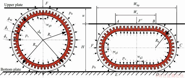
Fig. 1 Schematic diagram of GSHP phase change flattening process
The length of unbending curves AB and DE. Ws, increases with the punch stroke as flattening proceeds, which can be expressed as
 (3)
(3)
The radius of bending curves such as arc  and arc
  is
is
 (4)
(4)
The width of flattened GSHP Whp can be expressed as
 (5)
(5)
Assume that the cross-section area of grooved- sintered wick, Awick, remains constant during flattening, and can be calculated by
 (6)
(6)
where Rv is the vapor chamber radius of cylindrical GSHP, ��s is the wick thickness over tear section, ��t is the wick thickness in the groove section, wt is the width of tear and wg0 is the width of groove in the cylindrical GSHP.
The vapor area of flattened GSHP, Av, is
 (7)
(7)
Assume that the effective length of flattened GSHP is L and the vapor volume Vv can be expressed as
 (8)
(8)
If the vapor pressure in GSHP is not high enough, the buckling phenomenon with two kinks on the central line will occur during the flattening process as shown in Fig. 2. RUNTZ and HODGE [15] implied the buckling phenomenon using a collapse mode with four plastic hinges of pipe. The buckling phenomenon seriously decreases thermal performance of flattened heat pipe from two aspects: one is the increase of contact thermal resistance between flattened heat pipe and heat source (or cold source), and the other is the decrease of vapor area. The separation occurs from the outset between heat pipe and the plate in the center of the contact zone and increases the buckling degree as the compression proceeds and its buckling rate rb can be defined by the trigonometric function tan as
 (9)
(9)
2.2 Elasto-plastic finite element analysis
The entire phase change flattening process is very complicate because it is a high non-linearity of large deformation. The complexity of flattening process is the high non-linearity of a large elasto-plastic deformation including: 1) non-linear geometrical behavior due to large displacements, large rotations and large strains; 2) non-linear constitutive behavior of bimetallic pipe with porous internal layer due to the elasto-plastic characteristic of large deformation; 3) non-linear boundary condition due to friction and changing contact condition between the heat pipe and loading plates. An analytical method is difficult to analyze the non-linear deformation process. So the finite element is employed to solve such non-linear problems due to the rapid advancement of PC.
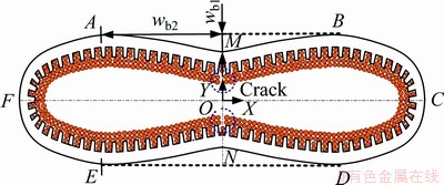
Fig. 2 Schematic diagram of flattened heat pipe with buckling
Several simple hypotheses are set before phase change flattening process is analyzed by the elasto- plastic finite element method: 1) the material of GSHP with porous internal layer is isotropic and isotropic hardening; 2) the calculation of phase change flattening process is based on the plane strain condition; 3) two flat and parallel plates are rigid; 4) the gravity of heat pipe is relatively small compared to punch load and vapor pressure, so the effect of gravity is ignored; 5) the effect of thermal expansion of GSHP during the flattening process is ignored due to its relatively small value; 6) the vapor pressure directly acts on the inner surface of sintered wick.
2.2.1 Variational principle
The non-linear stress��strain relationship due to the elasto-plastic characteristic of large deformation can be calculated by the incremental method. The virtual work- rate equation of the updated Lagrangian formulation is employed for finite element analyzing the incremental characteristics of the metal forming process. The equilibrium will be met at the incremental step t to t+��t through the principle of virtual work that can be written in general terms as


 (10)
(10)
where [B] represents strain rate-velocity matrix; [D]ep represents elemental elasto-plastic constitutive matrix; [N] represents shape function matrix; {p} represents the collection of surface forces; {b} represents the collection of volume forces; {����} represents the collection of displacement increment; {��} represents the collection of stress; V and Sp are the material volume and the surface on which the traction is prescribed.
2.2.2 Yield criterion
The GSHP is composed of an outer grooved pipe and an internal porous sintered wick. The grooved pipe is pore-free copper which is incompressible, and the sintered wick is copper powder sintered porous material with variable volume during flattening. Therefore, the yield criterion and constitutive model of grooved pipe and sintered wick should be discussed individually.
1) Porous material of sintered wick
The yield strength of powder sintered wick is relative to the matrix material and yield criterion reflects the effect of hydrostatic pressure on yielding based on the plastic deformation of powder sintered porous material, the basic form [16] is given by
 (11)
(11)
where I1 is the first invariant of stress tensor which reflects the effect of hydrostatic pressure on yielding and can be obtained as
 (12)
(12)
J2 is the second invariant of stress deviator which can be expressed as
 (13)
(13)
Y0 is the yield strength of matrix material; a1, a2 and a3 are the yield criteria of von Mises, a1 is equal to 3, a2 and a3 are functions of porosity f which is equal to am and b2n+1 respectively; a and b are determined by several factors, such as the compression process of porous material, sintered powder size and shape, and the size of porous material sample. The values of m and n are related to porosity f and determined by experiments. MAMALIS et al [17,18] proposed the calculation formulas for a and b as follows.
When 0��f��0.25,
 (14)
(14)
 (15)
(15)
When 0.25��f��0.6,
 (16)
(16)
 (17)
(17)
Therefore, the yield criterion Eq. (11) for powder sintered porous material can also be expressed as

 (18)
(18)
2) Compact material of grooved pipe
As for compact material of grooved pipe, f =0, a =0 and b=1, so the yield criterion of grooved pipe can be simplified as
 (19)
(19)
2.2.3 Constitutive model
Assume that the material of sintered heat pipe obeys von Mises yield criterion and Prandtl-Reuss stress��strain relation. Considering the elasto-plastic behavior, the constitutive relationship of material under the plane strain condition is given by
 (20)
(20)
where elasto-plastic matrix [D]ep is the sum of elastic matrix [D]e and plastic matrix [D]p. The elastic deformation of grooved pipe and sintered wick complies with Hooke��s Law, so the elastic matrix [D]e can be given as
 (21)
(21)
where G=E/2(1+n). The elastic modulus E and the Poisson ratio n can be obtained by mechanical testing respectively.
1) Porous material of sintered wick
The volume of sintered wick changes during the flattening process which means porous sintered wick is compressible and the Poisson ratio is below 0.5, thus classical plasticity theory based on constant volume is no longer suitable. Plasticity theory of real porous materials based on volume variable is adapted to establish the regularities of the plastic deformation of GSHP. MAMALIS et al [17,18] proposed the following basic equation of the flow theory of real porous material:
 (22)
(22)
According to Prandtl-Reuss flow law, Eq. (22) can be simplified as
 (23)
(23)
The effect of hydrostatic stress on plastic flow of porous material is little, thus stress deviator s��ij is introduced:
 (24)
(24)
Substituting Eq. (24) into Eq. (22), Eq. (23) can be simplified as

 (25)
(25)
where  and
and are equivalent plastic stress and equivalent plastic strain increment of porous material and can be calculated respectively as
 (26)
(26)
 (27)
(27)
where rr is the relative density of porous sintered wick; si is the stress strength, ei is the strain strength; s0 is the mean stress which is equal to dijsij/3 and de0 is the mean strain increment which is equal to dijdeij/3.
The yield criterion of isotropic hardening material in complex stress state obeys Mises yield function which reflects plastic hardening rule after the initial yield state. The subsequent yield stress is only relative to the total equivalent plastic strain instead of stress state and wick porosity and the incremental form of hardening law is
 (28)
(28)
where H�� is the rate of strain hardening
The relationship of elastic stress increment and strain increment is linear and obeys Hooke��s law, therefore
 (29)
(29)
Above all, the plastic matrix [D]p can be deduced under the plane strain condition,
 (30)
(30)
2) Compact material of grooved pipe
Prandtl-Reuss flow rule can also be adapted to describe the constitutive relationship of pore-free material plastic deformation. As for pore-free material of grooved pipe, porosity f =0(a=0, b=1), Eqs. (22), (26), (27) and (30) can be simplified as follows, respectively,
 (31)
(31)
 (32)
(32)
 (33)
(33)
 (34)
(34)
The equivalent stress��equivalent plastic strain relationship of porous sintered wick is represented by an n-power law of the form:
 (35)
(35)
where kwick is the strength coefficient of porous sintered wick.
The equivalent stress��equivalent plastic strain relationship of grooved pipe is
 (36)
(36)
where kw is the strength coefficient of grooved pipe.
2.2.4 Boundary conditions
1) Vapor pressure and air pressure
The air pressure on the GSHP is constant during the flattening process and the value is tested to be about 1.01��105 Pa in the present work. Heat pipes are always evacuated to high vacuum for several hours and then charged in a certain amount of working fluid. When heat pipe is heated to a relatively high temperature, the working fluid phase would change into vapor and generate high vapor pressure. The mechanism of vapor pressure in the heat pipe is saturated vapor pressure equation instead of ideal gas state equation [14]. The Antoine vapor pressure correlation is always used to calculate the saturated vapor pressure for pure fluids. Therefore, the water saturated vapor pressure pv in GSHP can be approximated by the Antoine��s equation [19]
 (37)
(37)
where when 0��Tv��483 K, A=16.37379, B=3876.659, C=-43.42.
The saturated vapour pressure is a function of temperature instead of the volume of vapor chamber based on the Antoine��s equation. In a words, the vapor pressure is a constant value at a given vapor temperature during the flattening process.
2) Friction
Although JOHNSON [20] reported that the effect of friction between rigid and parallel plates would be small during the quasi-static compression of a circular pipe, a modified Coulomb friction law [21] is adopted in the present study. The increment of nodal force acting on the contact node can be resolved into tangential and normal components ��ft and ��fn
 (38)
(38)
where n is the outward vector normal to the plate surface; t is vertical to n. The increment of tangential force ��ft, the direction of which coincides with the sliding direction, can be calculated by modified Coulomb��s friction law as [21]
 (39)
(39)
where m is the friction coefficient, physical meaning of C is critical relative sliding velocity of for quasi-sticking state and sliding state during flattening, and vr is the contact nodal sliding velocity relative to the plate movement.
2.2.5 Finite-element discretization
GSHP is divided into finite elements by performing the standard finite element discretization. The principle of virtual work rate equation and the constitutive relation are linear equations of rates at the incremental step t to t+��t. Integrating all the element stiffness equations, Eq. (12) yields a system of algebraic equation in the global stiffness matrix form:
 (40)
(40)
where {��d} is the global incremental matrix of displacement and [K] is the global stiffness matrix which can be calculated by
 (41)
(41)
{��p} is the global incremental matrix of node loading which can be expressed by

 (42)
(42)
2.2.6 Method of solution
The contact and separation conditions of nodes and the state of element keep invariant during each
increment. The increment of each loading step should be controlled in order to assure the accuracy of the integration scheme. The size of each loading step is calculated by an automatic load-stepping method as
 (43)
(43)
where ri is the weighting factor for the increment of each loading step.
The solution procedure can be summarized as follows: firstly, heat pipe is meshed using continuum quad elements and the flat plates are modeled as analytic rigid surface; secondly, set-up the initial and boundary conditions (air pressure and vapor pressure) and prescribe a fictitious plate displacement increment ���� at the beginning of step loading; thirdly, calculate stiffness matrix [K] and solve Eq. (40); fourthly, calculate the size of each loading step by Eq. (43) and its increment ��i=��i-1+ri����i; fifthly, update the geometry of the flattened heat pipe, displacements, stresses, the yield limit and boundary conditions if the convergence reaches the minimization of the force or displacement residual; finally, go to the third step until the upper plate reaches its finally punch stroke, and then execute the unloading procedure and output results .
3 Experimental
3.1 Fabrication of cylindrical GSHP
The grooved-sintered wick of heat pipe samples is shown in the Fig. 3 and the experimental specification is shown in Table 1. The grooves of grooved pipe were plastically formed by oil-filled high-speed spin forming method [22-24]. Spherical copper powder was sintered on the inner surface of grooved pipe as grooved-sintered wick at sintering temperature of 950 ��C for 3 h by solid state sintering method [25]. Miniature cylindrical GSHP was fabricated by following process: vacuum pumping, fluid charging [26], cold weld sealing [27] and plasma welding of the ends.
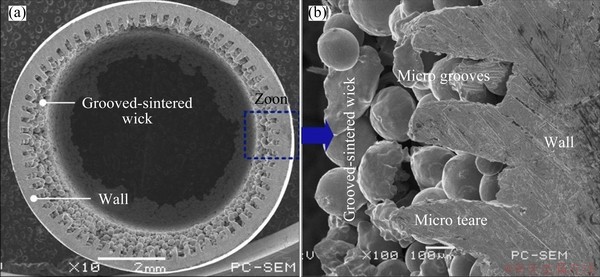
Fig. 3 SEM images of grooved-sintered wick structure
Table 1 Experimental specification of GSHP
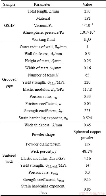
The heat pipes were evacuated to the pressure of 4��10-4 Pa and then charged the purified water with 100% fill ratio. The thickness of uniform sintered zone d1 was defined as the wick thickness of GHSP in the present work.
3.2 Experimental setup
According to phase change principle of heat pipe, a phase change flattening equipment was designed to fabricate flattened heat pipe and test the flattening process as shown in Fig. 4. Flattening equipment was a modified universal testing machine (Model: CMT6103, MTS Systems Corporation, USA) on which flattening plates were installed. The loading error and displacement error of universal testing machine were below 1%. The flattening plates consisted of bottom plate with its heating system and upper plate with its cooling system. Three heating robs (diameter d8mm, rated powder 500 W) were uniformly inserted into bottom plate. The power of heating robs was supplied by DC power supply. The K-type thermocouple was adhesively bonded on the side wall of cylindrical GSHP. The heating temperature was regulated by the temperature controller and the fluctuation was below ��1 ��C so as to guarantee constant vapor pressure in heat pipe. Three water channels were drilled in the upper plate to flow cooling water. The center one was inlet and the other two were outlets. Heat exchanger was installed in the back flow pathway to cool water and a pump was installed in the water bath to pump cooling water to upper plate.

Fig. 4 Schematic of experimental set-up for phase change flattening process
3.3 Flattening process
The phase change flattening process for fabrication of flattened GSHP can be divided into seven stages: 1) bonding K-type thermocouple on the side wall of cylindrical GSHP and placing cylindrical GSHP on the center of bottom plate; 2) adjusting the upper plate to cylindrical GSHP till close contact with the top surface of cylindrical GSHP; 3) setting the heating temperature of temperature controller and heat cylindrical GSHP by heating bottom plate; 4) moving the upper plate to press GSHP at a velocity of 10 mm/min after GSHP heating temperature achieves set value, and record punch loading, displacement, stress and strain by universal testing machine; 5) keeping compression for about 20 s as the upper plate reaches finally flattening height; 6) closing DC power supply to stop heating and pump cooling water to cool upper plate till the temperature of GSHP reaches room temperature; and 7) lifting the upper plate, and then the final flattened GSHP is formed. The heating temperature is the key factor which greatly affects the flatness of flattened heat pipe. If the heating temperature is too high, GHSP would expand and even explode, and flattening time would be prolonged.
4 Results and discussion
4.1 Strain analysis
4.1.1 Punch stroke
Figure 5 shows the distribution of equivalent plastic strain of flattened GSHP as flattening proceeds at vapor temperature of 480 K. It clearly shows that the equivalent strain distribution of flattened GSHP is quartered by two mutually perpendicular axes (axis-OO�� and axis-CF) due to its symmetry of flattening deformation. A quarter portion of the equivalent strain distributes and varies along circumferential direction of the wall. Large strain always occurs in the grooved- sintered wick yet rare in the grooved pipe. The plastic deformation increases as flattening proceeds and the maximum equivalent plastic strain  also increases with punch stroke. Before the heat pipe is laterally pressed, the circumferential distribution of equivalent plastic strain is uniform on the GSHP due to vapor pressure and the maximum equivalent plastic strain is only 0.01435 on the grooved-sintered wick. The plastic deformation of this stage can be used as a novel method to expand heat pipe which can be applied to heat pipe interference fit installation to decrease contact thermal resistance. When the punch stroke is 1 mm, the maximum equivalent plastic strain significantly increases to 0.1679. When the punch stroke is 5 mm, is 0.8561. When the punch stroke is less than 3 mm, the maximum equivalent plastic strain reaches its maximum value at the interface of vapor and grooved-sintered wick. Equivalent plastic strain circumferential uniformly exists at the straightened section of grooved wall and uniform zone wick: section AB and section DE. When the punch stroke is greater than or equal to 3 mm, the equivalent plastic strain reaches its maximum at the bending points C and F at the interface of vapor and wick.
4.1.2 Vapor temperature
Figure 6 presents equivalent plastic strain distribution of flattened GSHP with 4 mm punch stroke at different vapor temperatures. It shows that vapor temperature (or saturate vapor pressure) contributes little to equivalent plastic strain while greatly affects buckling rate of flattened GSHP. The buckling rate decreases with vapor temperature due to saturate vapor pressure. When the vapor temperature Tv is 300 K and vapor pressure pv is about 0.042 MPa, an obvious buckling phenomenon occurs at the section AB and section DE as shown in Fig. 6(a). When the vapor temperature Tv is 480 K and vapor pressure pv is about 1.9 MPa, buckling phenomenon is almost eliminated due to high saturate vapor pressure. The maximum equivalent plastic strain at bending points (points C and point F) decreases with vapor temperature due to buckling phenomenon. The equivalent plastic strain of sintered wick in the grooves on the straightened sections (sections AB and DE) distributes periodically due to the micro grooves. Above all, an optimal vapor temperature to flatten GSHP with good flatness is about 480 K.

Fig. 5 Equivalent plastic strain distribution of flattened GSHP during flattening
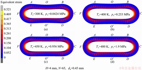
Fig. 6 Comparison of equivalent plastic strain of flattened heat pipe at different vapor temperatures
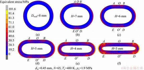
Fig. 7 Equivalent stress distribution of flattened heat pipe during flattening
4.2 Stress analysis
Figure 7 shows the distribution of equivalent plastic stress of GSHP as flattening proceeds at vapor temperature of 480 K. It clearly shows that the equivalent plastic stress contour of GSHP in the flattening process presents 1/4 symmetric distribution with OO�� and CF as the center line. Each 1/4 symmetry equivalent plastic stress contour varies along circumferential direction of the grooved pipe. The high stress mainly distributes on grooved pipe outer wall of GSHP and the wick/vapor chamber interface. The equivalent plastic stress circumferential along GSHP straight section AB and section DE varies little, where the maximum equivalent plastic stress is maintained at 56-62 MPa. The maximum equivalent stress  increases with the increase of punch stroke. Before the heat pipe is laterally compressed by the upper plate, the equivalent of stress uniformly distributes on the wall of GSHP and is 16.76 MPa. When the punch stroke is 1 mm, the maximum equivalent plastic stress suddenly increases to 61.51 MPa due to the large compression deformation of heat pipe. When the punch stroke reaches 5 mm, the maximum equivalent plastic stress is 101.6 MPa.
4.3 Punch load
Figure 8 shows the relationship between the punch load and punch stroke at room temperature of 300 K and vapor temperature of 480 K by both experiment and modeling. The modeling results are relatively consistent with the experimental results, which to some extents explain the reliability of the finite element model. It also clearly shows that the punch load is proportional to the punch stroke, which means the punch load increases with the punch stroke. During the flattening process, the contact points of loading application move outwards along the pipe, which would have the effect of shortening the bending arms such as BC, CD, EF and AF as shown in Fig. 1, producing high moments. Meanwhile, the geometric constrains as a small edge radius produce in vertical direction of diameter of pipe, which would increase its degree with flattening. Furthermore, the material strain hardens in the plastic range under severe compression, which also further increases the punch load. Compared with the punch load at different heating temperatures with the same punch stroke, the punch load at vapor temperature 480 K is much higher than that at room temperature 300 K, due to the fact that the higher vapor temperature means higher vapor pressure, which prevents the downward movement of the compression while reduces buckling rate and increases the punch load.
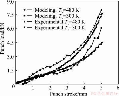
Fig. 8 Relationship of punch load and punch stroke
4.4 Buckling
The flatness of flattened GSHP is the key factor that determines the success of phase change flattening process, which depends on the elimination of the buckling phenomenon. Figure 9 presents the SEM images of flattening buckling phenomenon at room temperature Tv=300 K and vapor temperature Tv=480 K. Figure 9(a) shows SEM image of flattened GSHP without buckling phenomenon when the flattening process proceed at vapor temperature of 480 K. The flattened surface of AB and DE has good flatness, with the bending arcs and presenting elliptical rather than semi-circular shape. Figure 9(b) shows SEM image of flattened GSHP with serious buckling phenomenon at room temperature of 300 K. The flattened GSHP presents fallen ��8�� shape with obvious buckling phenomenon. Collapse takes place in the centerline OO�� and forms a large crack groove in the sintered wick. The buckling phenomenon greatly reduces the area of flattened GSHP vapor chamber and increases contact thermal resistance between heat pipes and the contact elements, meanwhile the crack groove hinders circumferential capillary flow of working fluid and reduces the thermal performance of GSHP.
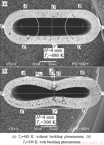
Fig. 9 SEM images of buckling phenomenon during heat pipe flattening
Figure 10 shows the buckling rate of flattened heat pipe in the range of punch strokes from 0 to 5 mm at different vapor temperatures by both experiment and modeling. It shows that the buckling rate of flattened GSHP increases with punch stroke. When GSHP is experimentally flattened at room temperature of 300 K, the buckling rate increases by nearly 7.3 times from 1 mm punch stroke of 0.015 to 5 mm punch stroke of 0.11. It could be seen clearly from Fig. 10 that the buckling rate of flattened GSHP decreases with vapor temperature Tv at a given punch stroke. As to punch stroke 5 mm, when vapor temperature Tv is 300 K, the experimental buckling rate is 0.11; when Tv gets to 450 K, the experimental buckling rate is 0.02; when Tv reaches 480 K, the buckling rate is 0.0015, which can be negligible. According to the formula of saturated vapor pressure, the internal vapor pressure of flattened GSHP is the function of vapor temperature. Higher vapor temperature means higher vapor pressure, which increases the anti-buckling capacity during the phase change flattening process. Therefore, the phase change flattening process is an efficient high-quality method to fabricate flattened GSHP with good flatness.

Fig. 10 Buckling rate of flattened heat pipe
4.5 Deformation geometry
The deformation geometry of GSHP continuously changes as flattening proceeds: the width of flattened GSHP Whp increases and the vapor chamber area Av decreases. These changes in the geometric structure will directly or indirectly affect the thermal performance of flattened GSHP. Therefore, it is necessary to carry out research on the variation laws among the width of the flattening heat pipe Whp, vapor chamber area Av and the punch stroke u.
4.5.1 Width of flattened GSHP
The relation of flattened GSHP width and height could be applied to the installation guidance of electronics cooling system. Figure 11 shows the width of flattened GSHP in the range of punch strokes of 0-5 mm at vapor temperature of 480 K. The experimental and the modeling results keep similar trend with the results by Eq. (3). As to a given punch stroke, the width of experimental flattened GSHP is the largest, followed by the modeling width, and the width by Eq. (3) is the smallest. When the punch stroke is 5 mm, the experimental width is 11.4 mm, the modeling width is 11.1 mm, and the width by Eq. (3) is 10.9 mm. This is because the bending arc of flattened GSHP in Eq. (3) is assumed to semicircle while the experimental bending arc is actually oval. The width and height of flattened GSHP is a approximately linear relationship.

Fig. 11 Width of flattened heat pipe
4.5.2 Vapor area
The vapor chamber is a vapor flowing channel from the evaporator section to the condenser section in flattened GSHP. The area of vapor chamber has a great impact on the vapor pressure drop. Figure 12 shows the vapor area of flattened GSHP in the range of punch strokes of 0-5 mm at vapor temperature Tv=480 K. The experimental, the modeling results and the results by Eq. (7) are very close to each other, which indicates the reliability of the finite element model to a certain extent. The vapor area rapidly decreases with the punch stroke. This is because the area of vapor chamber is a quadratic function of flattened GSHP height according to Eq. (7).
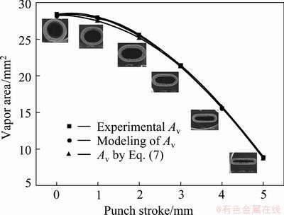
Fig. 12 Vapor area of flattened heat pipe
5 Conclusions
1) Phase change flattening process for fabrication of flattened GSHP is a non-linear elasto-plastic deformation process. This process can be divided into three stages: pipe expansion stage, pipe flattening stage and pipe spring-back stage. An elasto-plastic finite element model based on an updated Lagrangian formulation is developed to simulate phase change flattening process. Formulation and algorithms are also adapted to solve the nonlinear problems of geometrical changes, plasticity and boundary conditions in an incremental manner. A modified Coulomb friction law is specially considered.
2) The equivalent elasto-plastic strain distribution is similar to stress distribution during phase change flattening process of GSHP, with OO�� and CF as the center line in one-fourth symmetry and the straight sections AB and DE changing very little. The maximum equivalent plastic strain mainly occurs in the grooved-sintered wick/vapor interface of straight sections AB and DE or bending points C and F, while the maximum equivalent plastic stress distribution mainly occurs at the outer surface of grooved pipe.
3) The punch load is mainly related to punch stroke and vapor temperature of GSHP. Punch load increases with punch stroke due to deformed geometry and plastic hardening of GSHP during flattening. Higher vapor temperature during flattening process needs higher punch load due to its higher vapor pressure in GSHP.
4) The saturated vapor pressure in GSHP can be used to solve the buckling phenomenon during the flattening process. The higher the vapor temperature, the higher the saturated vapor pressure and the smaller the flattened heat pipe buckling rate. When the vapor temperature reaches 480 K, the buckling phenomenon of flattened GSHP can be well eliminated. When the lateral compression proceeds, the width of flattened GSHP increases and the area of vapor chamber decreases.
References
[1] MCGLEN R J, JACHUCK R, LIN S. Integrated thermal management techniques for high power electronic devices [J]. Applied Thermal Engineering, 2004, 24(8-9): 1143-1156.
[2] TSAI Y S, CHANG Y M, CHAN J H, WU S C, CHEN Y M. Enhancement of thermal performance in a sintered miniature heat pipe [J]. Journal of the Chinese Institute of Engineers, 2005, 28(2): 359-363.
[3] MOON S H, HWANG G, YUN H G, CHOY T G, KANG Y. Improving thermal performance of miniature heat pipe for notebook PC cooling [J]. Microelectronics Reliability, 2002, 42(1): 135-140.
[4] RUSSEL M K, YOUNG C, COTTON J S, CHING C Y. The effect of orientation on U-shaped grooved and sintered wick heat pipes [J]. Applied Thermal Engineering, 2011, 31(1): 69-76.
[5] JIANG Le-lun, TANG Yong, PAN Min-qiang. Effects of bending on heat transfer performance of axial micro-grooved heat pipe [J]. Journal of Central South University of Technology, 2011, 18(2): 580-586.
[6] HUANG X, FRANCHI G. Design and fabrication of hybrid bi-modal wick structure for heat pipe application [J]. Journal of Porous Materials, 2008, 15(6): 635-642.
[7] MOON S H, HWANG G, CHOY T G, KIM K S. Investigation of packaged miniature heat pipe for notebook PC cooling [J]. International Journal on Microcircuits and Electronic Packaging, 2000, 4339: 512-517.
[8] TAO H Z, ZHANG H, ZHUANG J, BOWMAN W J. Experimental study of heat transfer performance in a flattened AGHP [J]. Applied Thermal Engineering, 2008, 28(14-15): 1699-1710.
[9] LIPS S, LEFEVRE F, BONJOUR J. Physical mechanisms involved in grooved flat heat pipes: Experimental and numerical analyses [J]. International Journal of Thermal Sciences, 2011, 50(7): 1243-1252.
[10] ENGLAND A H, GREGORY P W. Finite lateral compression of an elastic-plastic fibre-reinforced tube: loading solutions [J]. Journal of the Mechanics and Physics of Solids, 1999, 47(2): 371-395.
[11] LEU D K. Finite-element simulation of the lateral compression of aluminium tube between rigid plates [J]. International Journal of Mechanical Sciences, 1999, 41(6): 621-638.
[12] GUPTA N K, SEKHON G S, GUPTA P K. Study of lateral compression of round metallic tubes [J]. Thin-Walled Structures, 2005, 43(6): 895-922.
[13] NEMAT-ALLA M. Reproducing hoop stress-strain behavior for tubular material using lateral compression test [J]. International Journal of Mechanical Sciences, 2003, 45(4): 605-621.
[14] JIANG Le-lun, TANG Yong, PAN Min-qiang, ZHOU Wei, LU Long-sheng. Phase change flattening process for axial grooved heat pipe [J]. Journal of Materials Processing Technology, 2012, 212(1): 331-338.
[15] de RUNTZ J A Jr, HODGE P G Jr. Crushing of a tube between rigid plates [J]. Journal of Applied Mechanics, 1963, 30(3): 391-395.
[16] KUHN H A, DOWNEY C L. Deformation characteristics and plasticity theory of sintered powder materials [J]. International Journal of Powder Metallurgy, 1971, 7: 15-25.
[17] MAMALIS A G, PETROSYAN G L, MANOLAKOS D E, HAMBARDZUMYAN A F. Mathematical modelling of plastic deformation processes of bimetallic tubes with porous-internal layer in conical dies [J]. Journal of Materials Processing Technology, 2006, 172(2): 243-248.
[18] MAMALIS A G, PETROSYAN G L, MANOLAKOS D E, HAMBARDZUMYAN A F. The effect of strain hardening in the extrusion of bimetallic tubes of porous internal layer [J]. Journal of Materials Processing Technology, 2007, 181(1-3): 241-245.
[19] SVOOBODA J, REPAS M, DYKYJ J. Calculation of the constants in Antoine's equation [J]. International Chemical Engineering, 1986, 26(2): 356-360.
[20] JOHNSON W. Impact strength of materials [M]. London: Edward Arnold Publishers Limited, 1983.
[21] ZHANG Yan-sheng, YANG Xiao-meng, LU Xin-zheng. Nonlinear finite element analysis for the wall pressure in a steel silo [J]. Industrial Structure, 2008, 38: 447-451.
[22] LI Yong, XIAO Hui, LIAN Bin, TANG Yong, ZENG Zhi-xin. Forming method of axial micro grooves inside copper heat pipe [J]. Transactions of Nonferrous Metals Society of China, 2008, 18(5): 1229-1233.
[23] TANG Y, CHI Y, CHEN J C, DENG X X, LIU L , LIU X K, WAN Z P. Experimental study of oil-filled high-speed spin forming micro-groove fin-inside tubes [J]. International Journal of Machine Tools & Manufacture, 2007, 47(7-8): 1059-1068.
[24] BAI Peng-fei, TANG Yong, TANG Biao, LU Long-sheng. Thermal performance of heat pipe with different micro-groove structures [J]. Journal of Central South University of Technology, 2008, 15(1) 240-244.
[25] JIANG Le-lun, TANG Yong, PAN Min-qiang, LI Chang-chun. Fabrication of sintered wick in mirco-grooved pipe [C]//2010 International Conference on Mechanic Automation and Control Engineering. Wuhan: MACE, 2010: 5868-5871. (in Chinese)
[26] LU Long-sheng, TANG Yong, YUAN Dong, JIANG Le-lun. Micro heat pipe manufacturing technology of vacuuming and filling work fluid [J]. Journal of Mechanical Engineering, 2009, 45(6): 122-127.
[27] TANG Yong, LU Long-sheng, DENG Da-xiang, YUAN Dong. Cold welding sealing of copper-water micro heat pipe ends [J]. Transactions of Nonferrous Metals Society of China, 2009, 19(3): 568-574.
��ƽ�����ս���Һо�ȹܵ����������
������1���� ��2���� ΰ1��������3��½����2
1. ��ɽ��ѧ ��ѧԺ������ 510006��
2. ����������ѧ ��е����������ѧԺ�����ݡ�510640��
3. ���ڹ���ѧԺ�����ڡ�322000
ժ Ҫ�����ŵ���оƬ�����ܶȵļ������Ӽ���Чɢ�ȿռ��������С�����и��ȵ��ʡ��߿ɿ��ԡ�������Ӧ�������������ص�ı�ƽ�ȹ��ѳ�Ϊ��������ʹ�õ����뵼��Ԫ��������˹����ս���Һо��ƽ�ȹܵļ������ѹ�����췽�������۷����˼������ѹ������������ȹܼ�����״�仯���ȹܵ����Դ���εij��ι��̣���������ʵ����ԡ�������֣����ѹ��������û���Ϊ�ȹ��ڲ��ı�������ѹ���̣����ѹ������У��ȹܼ�����״�仯�ܴ�����Ч����Ӧ����Ҫ�����ڱ�ƽ����Һо/���������ϣ���ѹ���¶�Ϊ480 Kʱ��ѹ���ȹܵ�������С���ɺ��Բ��ƣ����ѹ��������ѹ���¶ȵ����ߺ�ѹ��λ�Ƶ����������
�ؼ��ʣ��ȹܣ���Һо��ѹ�⣻�����Ա��Σ�����������ѹ
(Edited by Hua YANG)
Foundation item: Project (50905119) supported by the National Natural Science Foundation of China; Project (2012M510205) supported by China Postdoctoral Science Foundation; Project (PEMT1206) supported by the Open Foundation of Guangdong Province Key Laboratory of Precision Equipment and Manufacturing Technology, China; Project (S2012040007715) supported by Natural Science Foundation of Guangdong Province, China
Corresponding author: Le-lun JIANG; Tel: +86-20-39332153; E-mail: jianglel@mail.sysu.edu.cn
DOI: 10.1016/S1003-6326(13)62789-2
Abstract: With the rapid rising of heat flux and reduction of heat dissipating space of microelectronic devises, flattened sintered heat pipe has become an ideal conducting element of use in the electronic cooling field. A manufacturing technology named phase change flattening process is presented to fabricate the flattened grooved-sintered wick heat pipe (GSHP for short). Deformation geometry of flattened GSHP and the elasto-plastic deformation of flattening process are analyzed theoretically and verified by experiments. The results show that the vapor pressure inside sintered heat pipe during flattening process is determined by the saturated vapor pressure equation; the width and vapor area of flattened heat pipe change greatly as the flattening proceeds; the maximum equivalent strain distributes at the interface between wick and vapor in the flat section; the buckling phenomenon can be well eliminated when the flattening temperature reaches 480 K; phase change flattening punch load increases with flattening temperature and displacement.
