

ARTICLE
J. Cent. South Univ. (2019) 26: 1089-1098
DOI: https://doi.org/10.1007/s11771-019-4073-z

Numerical analysis on forced convection enhancement in an annulus using porous ribs and nanoparticle addition to base fluid
Majid SIAVASHI, Hamid Reza TALESH BAHRAMI, Ehsan AMINIAN, Hamid SAFFARI
School of Mechanical Engineering, Iran University of Science and Technology, Tehran, Iran
 Central South University Press and Springer-Verlag GmbH Germany, part of Springer Nature 2019
Abstract:
Miniaturization of electronic equipment has forced researchers to devise more effective methods for dissipating the generated heat in these devices. In this study, two methods, including porous media inserting and adding nanoparticles to the base fluid, are used to improve heat transfer in an annulus heated on both walls. To study porous media insert, porous ribs are used on the outer and inner walls independently. The results show that when porous ribs are placed on the outer wall, although the heat transfer enhances, the pressure drop increment is so considerable that performance number (the ratio of heat transfer enhancement pressure increment, PN) is less than unity for all porous rib heights and porous media permeabilities that are studied. On the other hand, the PN of cases where porous ribs were placed on the inner wall depends on the Darcy number (Da). For example, for ribs with Da=0.1 and Da=0.0001, the maximum performance number, PN=4, occurs at the porous ribs height to hydraulic diameter ratios H/Dh=1 and H/Dh=0.25. Under these conditions, heat transfer is enhanced by two orders of magnitude. It is found that adding 5% nanoparticles to the base fluid in the two aforementioned cases improves the Nusselt number and PN by 10%�C40%.
Key words:
nanofluid; porous media; annulus; heat transfer enhancement; internal flow��
Cite this article as:
Majid SIAVASHI, Hamid Reza TALESH BAHRAMI, Ehsan AMINIAN, Hamid SAFFARI. Numerical analysis on forced convection enhancement in an annulus using porous ribs and nanoparticle addition to base fluid [J]. Journal of Central South University, 2019, 26(5): 1089�C1098.
DOI:https://dx.doi.org/https://doi.org/10.1007/s11771-019-4073-z1 Introduction
Forced convective heat transfer is an important regime of energy exchange mechanisms, which has many applications in different areas such as electronic equipment cooling, power plants, desalination, heating, ventilating and air conditioning. However, increasing demands for energy and limited resources have forced scientists and engineers to devise methods that optimize the energy consumption. Optimization in heat transfer exchanging includes increasing heat transfer capability with a minimum pumping power increment. Many methods have been used in literature such as porous media inserting or increasing the base fluid conductivity by suspending some high conductive nanoparticles to improve heat transfer [1�C5]. For example, SHEIKHOLESLAMI et al [6] studied a homogeneous nanofluid force convective flow inside a lid-driven porous cavity in the presence of a magnetic field. SHEIKHOLESLAMI et al [7, 8] also published other good investigations on this topic. The results of this investigation show that the shape of nanoparticles could change the thermal behavior of the nanofluid. BARAGH et al [9] performed an experimental study on the forced convective heat transfer of a single phase flow inside a channel in the presence of porous media. They studied the effects of different arrangements of porous structures on the heat transfer and flow characteristics. Their results show that the channel fully filled with a porous medium has the best heat transfer improvement both in the laminar and turbulent regimes. HASSAN et al [10] studied convective heat transfer of a nanofluid flow over a wavy surface in a porous medium. They used the copper oxide as nanoparticles and considered the effects of the porosity. They showed that when the nanoparticles are added to the base fluid, the heat transfer is improved while the flow velocity is declined. RAIZAH et al [11] investigated the natural convection of a non-Newtonian nanofluid flow inside an inclined open cavity filled with a porous medium. SIAVASHI et al [12] studied the forced convective heat transfer of a nanofluid flow inside an annulus partially or completely filled with a porous medium. They used the two-phase mixture model to simulate the nanofluid flow and Darcy- Brinkman-Forchheimer equation to model the fluid flow inside the porous medium. They showed that there are optimal thicknesses for the porous medium height according to the flow Reynolds number and the nanofluid concentration. There are good review papers on the topic of nanofluid applications in Refs. [13, 14].
Porous ribs inside an annulus can be used as components placed on the top of electronic modules to cool them [15�C17]. This arrangement saves material usage against a porous layer, which completely covers the surface. The optimal arrangement of porous ribs has been investigated beforehand [18].However, utilization of porous ribs on both walls of an annulus or a two- dimensional channel where heat flux is applied on both walls is not studied yet.
In the present investigation, a numerical study has been done to study the heat transfer and hydrodynamic characteristics of an annulus heated on both inner and outer walls. The problem is divided into three steps. In the first and second steps, only porous ribs are positioned on one of the inner and outer walls. In the third step, the optimal conditions achieved in the previous steps are analyzed using a nanofluid. The nanofluid flow is analyzed using the two-phase mixture model and the flow in the porous medium is simulated using Darcy-Brinkman-Forchheimer equation. In this study, the effects of the height and permeability of porous ribs are analyzed.
2 Mathematical formulation
2.1 Problem description
The problem contains an annulus with length, inner and outer radii, 2, 0.08 and 0.2 m, respectively. The fluid is water as the base fluid, which may contain alumina nanoparticles dispersing into it. The volume fraction of nanoparticles could vary up to 5%. The problem is divided into two patterns: in the first configuration, porous ribs are attached to the inner wall of the annulus while in the second arrangement the porous ribs are on the outer wall. The height of the ribs could change in both configurations. A constant heat flux 500 W/m2 is applied on both inner and outer walls. The porosity of the ribs and Reynolds number of the flow are 0.9 and 1000, respectively. The distance of ribs and the width of the ribs are constant, 0.05 and 0.01 m, respectively.
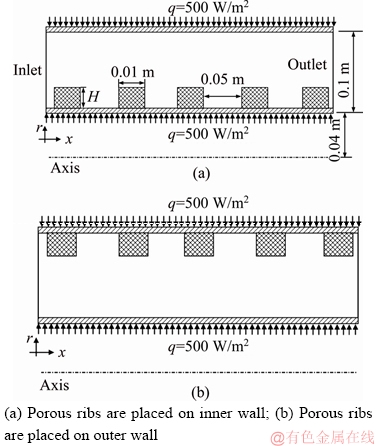
Figure 1 Schematic views of problem for cases:
Two-phase flows can be studied numerically by two distinct methods, including Euler-Lagrange and Euler-Euler approaches. In the Euler-Lagrange approach every particle is followed. Therefore the equation of motion of every particle must be solved [19]. In the case of nanofluid, according to the huge number of nanoparticles scattering in the base fluid, using the Euler-Lagrange technique is not practically applicable using the current computational facilities. On the other hand, in the Euler-Euler approach both liquid and gas-phase motions are considered in a homogeneous way [20]. In this technique, both phases are considered interpenetrating fluids, and the conservation of mass and momentum are satisfied by each phase independently [21]. Two-phase mixture model as an Euler-Euler approach has been used successfully in different studies including nanofluid flow with acceptable accuracy in recent years [22�C24]. The mixture model is a simplified Euler-Euler method for modeling n-phase flows. Simplifications are based on the assumption that the Stokes number is very smaller than unity (St<<1). It means that the nano-particles closely follow the main flow [25].
The details of this model are as follows:
1) Continuity equation:
 (1)
(1)
where  and ��m are the mass-averaged velocity and the mixture density respectively, which are defined as follows:
 (2)
(2)
 (3)
(3)
In the above equations, fk is the volume fraction of the kth phase.
2) Momentum equation:

 (4)
(4)
where ��m is the mixture viscosity written as follows:
 (5)
(5)
The correlation reported by MAHMOODI et al [2] is used to calculate the effective viscosity as follows:
 (6)
(6)
In Eq. (4),  is the drift velocity, which is written as follows [5]:
 (7)
(7)
where
 (8)
(8)
and
 (9)
(9)
In Eq. (8), fdrag is drag function which can be calculated using Schiller and Naumann��s correlation [7]:
 (10)
(10)
Energy equation [3, 4]:
 (11)
(11)
where ��m is the effective conductivity of the mixture which is calculated as follows:
 (12)
(12)
3) Volume fraction: The secondary phase volume fraction in the two-phase mixture model is calculated as follows [4]:
 (13)
(13)
4) Porous region: The flow field in the porous region can be simulated using Darcy-Brinkman- Forchheimer equation along with the two-phase mixture model as follows [8]:

 (14)
(14)
where Cd is the inertia coefficient of the porous medium which is calculated by the Kozeny-Carmen formula:
 (15)
(15)
The first term in the right hand side of Eq. (14) is the pressure gradient. It is the driving force flowing the fluid through the domain. The second and third expressions are Darcy and Brinkman terms, including distributed body force exerted by the porous medium and the viscous effects owing to boundaries inside the porous medium, respectively. The final expression is the Forchheimer term magnifying in high speed flows [17].
The following parameters are also defined to analyze different configurations.
Hydraulic diameter:
 (16)
(16)
in the current problem, Dh=0.2�C0.08=0.12 m.
Reynolds number:
 (17)
(17)
Nusselt number:
 (18)
(18)
where h is heat transfer coefficient.
2.2 Numerical procedure
The CFD code Ansys Fluent 16 which is a finite volume based code is used to simulate the problem. A second-order upwind scheme is applied to solve the conservation equations. For this purpose, the semi-implicit method for pressure- linked equation (SIMPLE) is joined the pressure and velocity fields. In the solution process, the convergence criterion of the iterative solution is less than 10-5 for the computing residuals, which guarantees the high accuracy of the results. The materials�� properties are given in Ref. [12].
2.3 Grid generation and code validation
To check the grid independency of the current problem, numerous rectangular uniform grid distributions are examined.Different grids are produced similar to what is shown in Figure 2. It is finer near the annulus walls so that different gradient especially temperature and velocity gradients could be captured with acceptable accuracy. The variations of Nu of different grid numbers are given in Figure 3. From this figure, it could be found that the structured grid with 50��1500 cells (in r and x directions respectively) is acceptable considering the computational cost and solution accuracy.
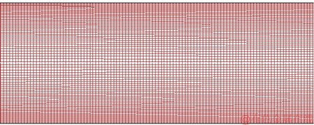
Figure 2 Grid generated for current problem
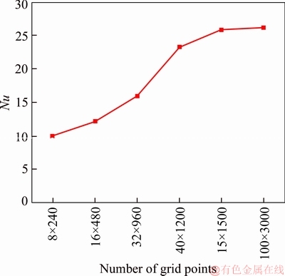
Figure 3 Variations of Nusselt number with different grid numbers
To verify the code accuracy to simulate the current problem, two different validation cases are presented. In the first case, the accuracy of the current procedure for simulating nanofluid flow is verified against experimental results of WEN et al [26] and numerical investigation of G KTEPE et al [27]. In this validation case, Re=1050 and nanofluid is alumina/water mixture with a volume fraction of 1.6%. As it can be seen from Figure 4, the current simulation is in good agreement with the presented references.
The numerical results of MAHDAVI et al [28] and experimental results of PAVEL et al [29] are used to verify the current simulation accuracy for simulating fluid flow in porous media. The validation case is a tube where a porous medium is attached to its internal wall. 40% of the tube is filled with a porous medium with Da=10�C4 with a constant heat flux applied on its external wall. The comparison is given in Figure 5 where it can be seen that a good agreement exists between the current simulation and those of the literature.

Figure 4 Verification of current procedure against results of WEN et al [26] and G KTEPE et al [27]
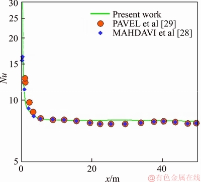
Figure 5 Verification of current procedure against results of MAHDAVI et al [28] and PAVEL et al [29]
3 Results and discussion
3.1 Porous ribs positioned on inner wall
The variations of the Nusselt number with respect to the porous rib height having different permeabilities are given in Figure 6. Because of the larger area of the outer surface, as it expected that the outer wall has a greater heat transfer rate when the porous ribs are not used in the problem. Therefore, the outer wall has a larger temperature and lower heat transfer coefficient. As it can be seen from Figure 6, the heat transfer coefficients of the outer wall of both cases Da=0.0001 and Da=0.1 are lower than that of the inner surface (in the case H/Dh=0). However, when porous ribs are used on the inner wall, the inner wall Nu number increases rapidly. Under these conditions, the fluid is forced to flow through tortuous ducts inside the porous medium. Although the random motion of the fluid flow increases the pressure loss, it increases heat transfer considerably because the thermal boundary layer thickness is decreased [30]. On the other hand, when the Da number is increased, the porous medium becomes denser and less permeable to the fluid. Under these conditions, heat transfer is
improved significantly and pressure loss becomes noticeable. For example, in Figure 6, when the Da number is decreased from 0.1 to 0.0001, the inner wall Nusselt number increases by two orders of magnitude. On the other hand, by increasing the porous rib height placed on the inner wall or increasing the Da number, the flow is forced to scope to the clear region between the porous ribs top and the outer wall (Figure 7). Under these conditions, the convective heat transfer on the outer wall is improved and the relevant Nusselt number increases. Finally, the total heat transfer rate becomes the maximum where the porous rib height and hydraulic diameter becomes equal (H/Dh=1). Under these conditions, the porous media enhance heat transfer on both walls.
The effects of porous rib height on the pressure loss are given in Figure 8. It can be seen that as the porous rib height is increased, the pressure drop increases dramatically. It means that the pumping power required to flow the fluid increases, which leads to much higher power consumption. For example, when the Da number is decreased from 0.1 to 0.0001, the pressure drop is increased by 10 times.
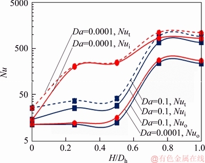
Figure 6 Variation of porous ribs height on Nusselt number
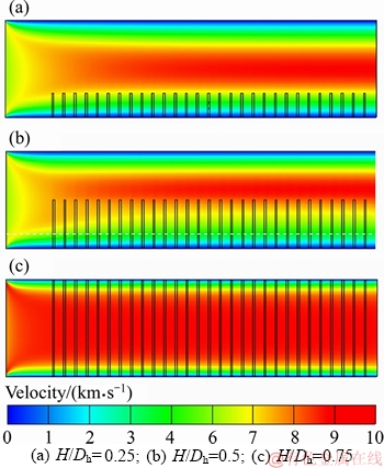
Figure 7 Velocity contours of configurations:(ribs placed on inner wall)
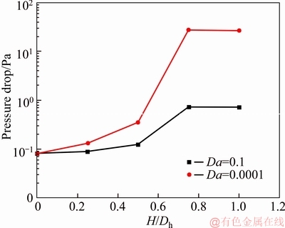
Figure 8 Variations of pressure drop with respect to porous rib height (ribs placed on inner wall)
On the other hand, it is preferred to miniaturize these cooling systems to be used in electronic equipment with a minimum pumping power. Therefore, the optimal case must be selected more precisely. In the optimal case, the value of heat transfer enhancement must correspond to an acceptable pressure loss increment. To compare the heat transfer improvement and the corresponding pressure loss increase, the performance number (PN) is defined as follows [12]:
 (19)
(19)
where subscripts i and o refer to the values related to inner and outer walls, respectively. Subscript base refers to conditions where no porous rips are applied in the annulus and the fluid is pure water without nano-particles addition. The dependency of PN on the porous ribs height is given in Figure 9. It can be seen that where the maximum PN occurs depends on the Da number. For example, when high permeable porous ribs were inserted into the annulus, the maximum PN occurs where the porous ribs height is increased to approach the outer wall.On the other hand, in the case Da=0.0001, the maximum PN is achieved when H/Dh=0.25. In other words, when the porous rib height is increased to greater values, the pressure drop becomes so considerable that PN approaches zero. However, the maximum value of PN for Da=0.0001 (PN=5) is greater than that in the case Da=0.1 (PN=4) by 20%.
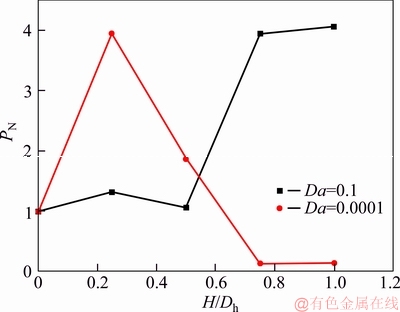
Figure 9 Effects of porous ribs height on PN for cases Da=0.1 and Da=0.0001 (ribs placed on inner wall)
The variations of outlet temperature with respect to the radius in different conditions of using porous ribs are given in Figure 10. It can be seen when porous ribs are used, the wall temperature is reduced while the mean temperature remains constant. This outcome results in a higher Nusselt number.
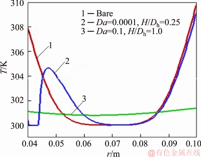
Figure 10 Variation of outlet temperature under different conditions of using porous ribs
3.2 Porous ribs positioned on outer wall
In this section, thermal behaviors of the annulus are studied when porous ribs are positioned on the outer wall. The effects of porous ribs height on the Nusselt number are shown in Figure 11. Again, it can be seen that increasing porous rib height increases heat transfer on both walls. An important point is that the behaviors of the Nu number are different for cases Da=0.1 and Da=0.0001. As it has been in the previous section, when no porous rib is used on both walls (H/Dh=0), the Nu of the inner wall is greater than that of the outer one. However, in the high Da number of the current configuration, when the porous rib height is increased, the Nu of the outer wall becomes slightly greater than that of the inner wall. This behavior exists up to where the porous rib height becomes 75% of the hydraulic diameter. After this limit, the inner wall Nusselt number becomes greater than that of the outer one. However, in the case Da=0.0001, the inner wall Nusselt is greater than that of the outer one for all porous rib heights. The inner wall due to its smaller area has a lower heat transfer rate, leading to a smaller wall temperature. However, the current study shows that the outer wall Nu could not considerably be greater than the inner one even with the expense of using porous ribs, which leads to higher pumping costs. This outcome results in nearly the same total Nusselt number for bare inner wall and porous rib equipped outer wall.
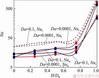
Figure 11 Effects of porous ribs height on Nu (ribs placed on outer wall)
The contours of temperature for different porous rib heights are given in Figure 12. From Figure 12(a), it can be seen that due to the presence of porous ribs, the streamlines shift from the outer wall to the inner wall. This outcome helps more heat to be convected from the inner wall. This consequence causes that the temperature gradient near the inner wall increases (the red zone becomes narrower). On the other hand, it can be seen from Figure 12 that as the porous ribs height increases, the temperature gradient near the outer wall increases, which results in a better heat transfer.
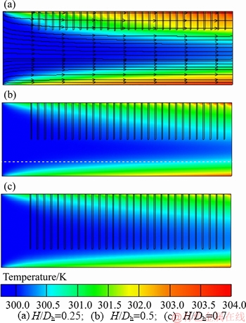
Figure 12 Contours of temperature for cases:(Da=0.0001, ribs placed on outer wall)
The pressure losses of the annulus when porous ribs with different permeability were used on the outer wall are shown in Figure 13. The global trend of this figure is the same as what is shown in Figure 13. Using low permeable or longer porous ribs leads to higher pressure losses.
The performance numbers of porous ribs with different permeabilities are shown in Figure 14. It can be seen that PN of the case with ribs having very low permeabilities decreases as the porous ribs height is increased. In fact, Figure 14 is the outcome of Figures 13 and 12. It can be seen that as the low permeable height increases, the Nussle number increases (Figure 12) but the pressure drop increase is so considerable (Figure 13) that the PN decreases finally. Therefore, it can be concluded that using lower permeable porous ribs on the outer wall is not economical at all, which leads to very small heat transfer enhancement at the expense of very high pumping power. The same condition exists for cases with higher Da except when the porous ribs height approaches the hydraulic diameter.
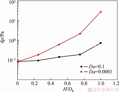
Figure 13 Variation of pressure loss with respect to porous ribs height (ribs placed on outer wall)
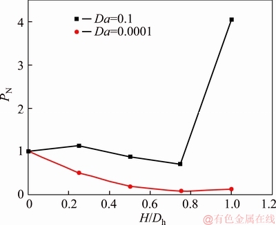
Figure 14 Variation of PN with respect to porous ribs height and Da (ribs placed on outer wall)
In other cases, the economic achievement of this arrangement is not significant.
3.3 Effect of nanoparticle addition
In previous sections, thermal and hydrodynamic behaviors of an annulus when inner or outer walls are equipped with porous ribs are analyzed. It has been seen that when the porous ribs are positioned on the outer wall, no significant enhancement is achieved. In the cases where porous ribs are placed on the inner wall, the optimal porous ribs height depends on the porous medium permeability. Under the conditions, when the porous ribs are positioned on the inner wall, two cases giving the highest PN have been considered to study the effects of nanoparticles additions.
Effects of nanoparticles addition to the base fluid on the Nu for the two aforementioned optimal conditions are given in Figure 15. It can be seen that the nanoparticle addition to the base fluid could also enhance heat transfer by 10%�C40% depending on the porous media permeability. Nanoparticle addition does not increase pressure drop considerably [12]. The main factor changing PN is Nu growth. Therefore, as it can be seen from Figure 16 that PN is also enhanced by 10%�C40%, which is the same as Nusselt number enhancement.
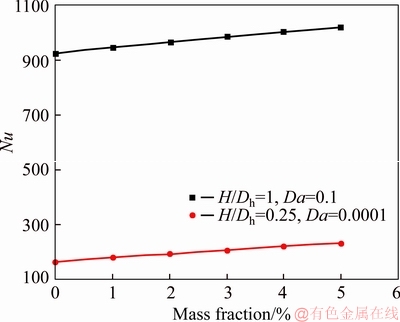
Figure 15 Effect of nanoparticle addition to base fluid on Nu for different cases (H/Dh=0.25, Da=0.0001; H/Dh=1, Da=0.1)
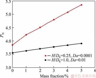
Figure 16 Effects of nanoparticle addition to base fluid on PN
4 Conclusions
The current study is done to investigate how much the forced convective heat transfer inside an annulus using porous media inserting and nanoparticles adding to the base flow. The annulus is heated externally by a constant heat flux on both inner and outer walls. Two cases are considered to study the effect of porous media. In one case, the porous ribs are attached to the inner, and in another case, the porous ribs are on the external surface. A performance number is defined, which compares the heat transfer enhancement and pressure drop increment. The effects of nanoparticle addition are studied on optimal PN of the previous cases. The results can be summarized as follows:
1) The maximum Nu of the first and configuration apart from the porous media permeability occurs where Dh/H=1. Under this condition, the heat transfer on both walls is enhanced by about two orders of magnitude, depending on the porous ribs position and porous media permeability.
2) Although the increasing porous ribs height improves heat transfer, it considerably increases pressure drop. For example, a pressure drop increment for cases with Dh/H=1 is about one order of magnitude depending on the porous media permeability and porous rib arrangement.
3) The porous medium height where the PN is maximal depends on the permeability and position of porous ribs.
4) In the case where the porous ribs are placed on the inner wall, the porous medium height at which the maximum PN is the maximum, depending on the Da. If porous media with high permeability is used, the PN of thicker porous ribs is greater. For example, the PN of porous ribs with H/Dh=1 and Da=0.1 is the maximum (PN=4). On the other hand, the maximum PN of porous ribs with lower permeabilities occurs at a smaller height. For example, the PN of porous ribs with H/Dh=0.25 is the maximum (PN=4).
5) In the second case, where the porous ribs are placed on the outer wall, although the heat transfer is enhanced by using porous ribs, the overall outcome is so that using porous media is not economical and PN is less the unity in nearly all cases.
6) The results show that the nanoparticle addition to the base fluid in optimal cases (porous ribs place on inner wall; H/Dh=1, Da=0.1; H/Dh=0.25, Da=0.0001) could improve PN by 10%�C40% depending on the porous ribs permeabilities.
References
[1] MAJID S, MOHAMMAD J. Optimal selection of annulus radius ratio to enhance heat transfer with minimum entropy generation in developing laminar forced convection of water-Al2O3 nanofluid flow [J]. Journal of Central South University, 2017, 24(8): 1850�C1865.
[2] MAHMOODI M, KANDELOUSI S. Kerosene-alumina nanofluid flow and heat transfer for cooling application [J]. Journal of Central South University, 2016, 23(4): 983�C990.
[3] ZAIB A, BHATTACHARYYA K, SHAFIE S. Unsteady boundary layer flow and heat transfer over an exponentially shrinking sheet with suction in a copper-water nanofluid [J]. Journal of Central South University, 2015, 22(12): 4856�C4863.
[4] HUSSAIN T, SHEHZAD S A, ALSAEDI A, HAYAT T, RAMZAN M. Flow of Casson nanofluid with viscous dissipation and convective conditions: A mathematical model [J]. Journal of Central South University, 2015, 22(3): 1132�C1140.
[5] SARI M R, KEZZAR M, ADJABI R. Heat transfer of copper/water nanofluid flow through converging-diverging channel [J]. Journal of Central South University, 2016, 23(2): 484�C496.
[6] SHEIKHOLESLAMI M. CuO-water nanofluid flow due to magnetic field inside a porous media considering Brownian motion [J]. Journal of Molecular Liquids, 2018, 249: 921�C929.
[7] SHEIKHOLESLAMI M. Influence of magnetic field on Al2O3-H2O nanofluid forced convection heat transfer in a porous lid driven cavity with hot sphere obstacle by means of LBM [J]. Journal of Molecular Liquids, 2018, 263: 472�C488.
[8] SHEIKHOLESLAMI M, HAQ R, SHAFEE A, LI Z. Heat transfer behavior of nanoparticle enhanced PCM solidification through an enclosure with V shaped fins [J]. International Journal of Heat and Mass Transfer, 2019, 130: 1322�C1342.
[9] BARAGH S, SHOKOUHMAND H, AJAROSTAGHI S S M, NIKIAN M. An experimental investigation on forced convection heat transfer of single-phase flow in a channel with different arrangements of porous media [J]. International Journal of Thermal Sciences, 2018, 134: 370�C379.
[10] HASSAN M, MARIN M, ALSHARIF A, ELLAHI R. Convective heat transfer flow of nanofluid in a porous medium over wavy surface [J]. Physics Letters A, 2018, 382(38): 2749�C2753.
[11] RAIZAH Z A S, ALY A M, AHMED S E. Natural convection flow of a power-law non-Newtonian nanofluid in inclined open shallow cavities filled with porous media [J]. International Journal of Mechanical Sciences, 2018, 140: 376�C393.
[12] SIAVASHI M, TALESH BAHRAMI H R, SAFFARI H. Numerical investigation of flow characteristics, heat transfer and entropy generation of nanofluid flow inside an annular pipe partially or completely filled with porous media using two-phase mixture model [J]. Energy, 2015, 93(2): 2451�C2466.
[13] MAHIAN O, KOLSI L, AMANI M, ESTELL P, AHMADI G, KLEINSTREUER C, MARSHALL J S, TAYLOR R A, ABU-NADA E, RASHIDI S, NIAZMAND H, WONGWISES S, HAYAT T, KASAEIAN A, POP I. Recent advances in modeling and simulation of nanofluid flows-part II: Applications [J]. Physics Reports, 2019, 791: 1�C59. DOI: doi.org/10.1016/j.physrep.2018.11.003.
[14] MAHIAN O, KOLSI L, AMANI M, ESTELL P, AHMADI G, KLEINSTREUER C, MARSHALL J S, SIAVASHI M, TAYLOR R A, NIAZMAND H, WONGWISES S, HAYAT T, KOLANJIYIL A, KASAEIAN A, POP I. Recent advances in modeling and simulation of nanofluid flows�Cpart I: Fundamental and theory [J]. Physics Reports, 2019, 790: 1�C48.
[15] JAVED M, FAROOQ M, AHMAD S, ANJUM A. Melting heat transfer with radiative effects and homogeneous�C heterogeneous reaction in thermally stratified stagnation flow embedded in porous medium [J]. Journal of Central South University, 2018, 25(11): 2701�C2711.
[16] VALIPOUR P, GHASEMI S E, VATANI M. Theoretical investigation of micropolar fluid flow between two porous disks [J]. Journal of Central South University, 2015, 22(7): 2825�C2832.
[17] SIAVASHI M, BAHRAMI H R T, AMINIAN E. Optimization of heat transfer enhancement and pumping power of a heat exchanger tube using nanofluid with gradient and multi-layered porous foams [J]. Applied Thermal Engineering, 2018, 138: 465�C474.
[18] SIAVASHI M, BAHRAMI H R T, SAFFARI H. Numerical investigation of porous rib arrangement on heat transfer and entropy generation of nanofluid flow in an annulus using a two-phase mixture model [J]. Numerical Heat Transfer, Part A: Applications, 2017, 71(12): 1251�C1273.
[19] PAKRAVAN H A, YAGHOUBI M. Analysis of nanoparticles migration on natural convective heat transfer of nanofluids [J]. International Journal of Thermal Sciences, 2013, 68: 79�C93.
[20] SOKOLICHIN A, EIGENBERGER G, LAPIN A, LUBERT A. Dynamic numerical simulation of gas-liquid two-phase flows Euler/Euler versus Euler/Lagrange [J]. Chemical Engineering Science, 1997, 52(4): 611�C626.
[21] LOU W, ZHU M. Numerical simulation of gas and liquid two-phase flow in gas-stirred systems based on Euler�CEuler approach [J]. Metallurgical and Materials Transactions B, 2013, 44(5): 1251�C1263.
[22] BAHIRAEI M, HANGI M, RAHBARI A. A two-phase simulation of convective heat transfer characteristics of water�CFe3O4 ferrofluid in a square channel under the effect of permanent magnet [J]. Applied Thermal Engineering, 2019, 147: 991�C997.
[23] KHOSRAVI-BIZHAEM H, ABBASSI A. Effects of curvature ratio on forced convection and entropy generation of nanofluid in helical coil using two-phase approach [J]. Advanced Powder Technology, 2018, 29(4): 890�C903.
[24] NAJAFI KHABOSHAN H, NAZIF H R. Heat transfer enhancement and entropy generation analysis of Al2O3-water nanofluid in an alternating oval cross-section tube using two-phase mixture model under turbulent flow [J]. Heat Mass Transfer, 2018, 54(10): 3171�C3183.
[25] KRISTIAWAN B, SANTOSO B, WIJAYANTA A T, AZIZ M, MIYAZAKI T. Heat transfer enhancement of TiO2/water nanofluid at laminar and turbulent flows: A numerical approach for evaluating the effect of nanoparticle loadings [J]. Energies, 2018, 11(6): 1�C15.
[26] WEN D, DING Y. Experimental investigation into convective heat transfer of nanofluids at the entrance region under laminar flow conditions [J]. International Journal of Heat and Mass Transfer, 2004, 47(24): 5181�C5188.
[27] GKTEPE S, ATALIK K, ERTURK H. Comparison of single and two-phase models for nanofluid convection at the entrance of a uniformly heated tube [J]. International Journal of Thermal Sciences, 2014, 80: 83�C92.
[28] MAHDAVI M, SAFFAR-AVVAL M, TIARI S, MANSOORI Z. Entropy generation and heat transfer numerical analysis in pipes partially filled with porous medium [J]. International Journal of Heat and Mass Transfer, 2014, 79: 496�C506.
[29] PAVEL B I, MOHAMAD A A. An experimental and numerical study on heat transfer enhancement for gas heat exchangers fitted with porous media [J]. International Journal of Heat and Mass Transfer, 2004, 47(23): 4939�C4952.
[30] MAEREFAT M, MAHMOUDI S Y, MAZAHERI K. Numerical simulation of forced convection enhancement in a pipe by porous inserts [J]. Heat Transfer Engineering, 2011, 32(1): 45�C56.
(Edited by YANG Hua)
���ĵ���
���ö����Ƭ�������������Һǿ������ͨ����ǿ�ƶ�������ֵ����
ժҪ�������豸��С�ͻ���ʹ�о���Ա��Ƴ�����Ч�ķ������ͷ��豸�в������������ڴ��о��У�ͨ���ڻ�Һ�в������ʺͼ������������ַ������Ը��������������ϼ��ȵĻ���ͨ���Ĵ��� ���ܡ�Ϊ���о������Ƕ�룬�ֱ����������ʹ�ö����Ƭ������������������Ƭ�������ʱ�����ܴ�����ǿ����ѹ�����൱�������������о��Ķ����Ƭ�߶����������Ե����ܲ���(PN)��������������ѹ������֮�Ⱦ�С��1���������Ƭ�����ڱ�ʱ��PNȡ����Darcy��(Da)�����磬����Da=0.1��Da=0.0001����Ƭ�����������PN=4�����ڶ����Ƭ�߶���ˮ��ֱ����ΪH/Dh=1��H/Dh=0.25������Щ����£�������ǿ�������������������������������������£��ڻ�Һ�м���5%����������ʹNusselt����PN���10%~40%��
�ؼ��ʣ��������壻����ʣ�����ͨ����ǿ�����ȣ��ڲ���
Received date: 2018-11-30; Accepted date: 2019-01-03
Corresponding author: Hamid Reza TALESH BAHRAMI, PhD, Researcher; E-mail: h_talesh@mecheng.iust.ac.ir; ORCID: 0000-0002- 0731-8316
Abstract: Miniaturization of electronic equipment has forced researchers to devise more effective methods for dissipating the generated heat in these devices. In this study, two methods, including porous media inserting and adding nanoparticles to the base fluid, are used to improve heat transfer in an annulus heated on both walls. To study porous media insert, porous ribs are used on the outer and inner walls independently. The results show that when porous ribs are placed on the outer wall, although the heat transfer enhances, the pressure drop increment is so considerable that performance number (the ratio of heat transfer enhancement pressure increment, PN) is less than unity for all porous rib heights and porous media permeabilities that are studied. On the other hand, the PN of cases where porous ribs were placed on the inner wall depends on the Darcy number (Da). For example, for ribs with Da=0.1 and Da=0.0001, the maximum performance number, PN=4, occurs at the porous ribs height to hydraulic diameter ratios H/Dh=1 and H/Dh=0.25. Under these conditions, heat transfer is enhanced by two orders of magnitude. It is found that adding 5% nanoparticles to the base fluid in the two aforementioned cases improves the Nusselt number and PN by 10%�C40%.
