
Magnetic force improvement and parameter optimization for magnetic abrasive polishing of AZ31 magnesium alloy
S. O. KIM1, J. S. KWAK2
1. Graduate School of Mechanical Engineering, Pukyong National University, South Korea;
2. School of Mechanical Engineering, Pukyong National University, South Korea
Received 12 June 2008; accepted 5 September 2008
Abstract:
The magnetic force acting on workpiece to be machined plays a significantly important role in magnetic abrasive polishing process. But in a case of polishing nonferrous materials, the strength of magnetic force is very low and it leads lower polishing efficiency. The magnesium alloy that has superior mechanical properties for industrial application such as a lightweight and high specific strength is one of the most famous nonferrous materials. An improving strategy of the magnetic force for the AZ31 magnesium alloy installed with a permanent magnet was proposed and experimental verification was carried out. For the proposed strategy, the effect of process parameters on the surface roughness of the AZ31 magnesium alloy was evaluated by a design of experimental method.
Key words:
magnetic abrasive polishing process; magnetic force improvement; nonferrous material; permanent magnet; process parameter;
1 Introduction
Magnesium alloy is one of the lightweight structural materials. The use of magnesium alloy is expanding, particularly in electronic and automobile industries due to its high specific strength and high specific stiffness [1-3]. Especially, magnesium alloy is applied to exterior parts of electronic products such as mobile phone and lap-top computer because of its strong isolation ability for electron waves. In these exterior parts, the finishing process of magnesium surface is very important to increase the quality of products. But it is very difficult to polish the surface of magnesium material because of its danger of fire ignition and fragility properties[4-6]. So, magnetic abrasive polishing (MAP) process is proposed to solve those problems for polishing of magnesium alloys.
Since the MAP has very flexible tool including iron powder and abrasive particle, not only cutting force and generated temperature are lower than other machining processes but also it is possible to polish the free surface of products. In spite of these advantages, efficiency of polishing is not acceptable in a case of nonferrous materials because of their lower magnetic forces on surface of materials. In past years, many researches such as study on the MAP of a nonferrous pipe were carried out. But there were few researches for improving magnetic force of the nonferrous materials in the MAP process.
In this study, the improving strategy of magnetic force on the MAP of AZ31 magnesium alloy was proposed. And optimization of process parameters for the MAP was tried to get better surface roughness of the AZ31 magnesium.
2 Magnetic abrasive polishing
2.1 Principle of MAP
Since the MAP could control flexibly the cutting force by adjusting magnetic density flux, this process was used to produce efficiently good surface of the nano-meter grade on flat, internal and external surface[7]. Magnetic assisted machining process is relatively new developed technology for finishing, cleaning, de-burring and burnishing of conventional metals and advanced engineering materials.
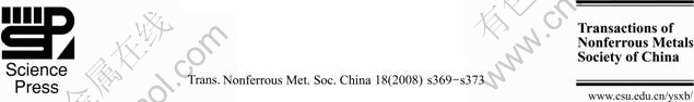
Most of the magnetic assisted machining processes are fundamentally based on the electro-magnetic behavior of magnetic abrasive particles in the magnetic field. In the MAP process, the magnetic force plays a dominant role for the formation of flexible magnetic abrasive brush[8]. Fig.1(a) shows a schematic drawing of the MAP process. Fig.1(b) shows magnetic abrasives mixed with iron particles and abrasive particles. For increasing the polishing efficiency, a variety of grain size can be used on the MAP process[9].
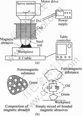
Fig.1 Schematic drawing and abrasives for MAP: (a) Schematic drawing of MAP; (b) Composition of magnetic abrasives
In the MAP, magnetic flux density is a very important factor. When the intensity of the magnetic flux density occurred by the DC current in coils is linearly increased, a normal force component at the surface on the workpiece is increased. So the larger current supplied leads the more improvement in a machining capability.
2.2 MAP of nonferrous materials
The magnetic density flux of ferrous materials was measured to compare with that of nonferrous materials. Fig.2(a) presents the measuring method for the magnetic density flux on the workpiece. As shown in Fig.2(a), the magnetic density flux according to distance from inductor��s center point was measured by a gauss meter. As shown in Fig.2(b), the magnetic density flux of the ferrous material was generally higher than that of the nonferrous material. The largest magnetic density flux was arrived at the 5 mm from the center point of the inductor in both situations. The maximum difference of the magnetic density flux between ferrous and nonferrous
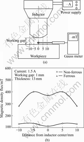
Fig.2 Characteristics of magnetic density flux on surface of workpiece: (a) Measuring method for magnetic density flux on workpiece; (b) Magnetic density flux for ferrous and nonferrous materials
materials was about 250 mT. So, the MAP process can not polish effectively the non- ferrous materials because of lower normal pressure.
3.1 Magnetic force improvement strategy
To improve the magnetic force for the MAP of magnesium alloy plate, a permanent magnet (NdBFe) was installed at the opposite side of the workpiece (nonferrous materials). The effect of polarity (N-S pole) with the permanent magnet is larger than without the permanent magnet on the opposite side of the magnesium alloy plate. And there are no chemical reactions when coolant is applied for the MAP of the magnesium alloy.
Fig.3(a) shows the measuring method for the magnetic density flux of the workpiece with a permanent magnet. In this study, the permanent magnet that had the magnetic density flux of 135 mT was installed. As shown in Fig.3(b), the magnetic density flux with the magnet was increased by about 30% compared with the situation of without the magnet. If the stronger permanent magnet was installed, the higher magnetic density flux was achieved.
Fig.3 Magnetic force improvement with permanent magnet (NdBFe): (a) Measuring method for magnetic density flux on workpiece with permanent magnet; (b) Magnetic density flux of surface with permanent and without magnet
3.2 Experimental set-up
In this study, the AZ31 magnesium alloy plate with a thickness of 0.6 mm was used. This magnesium alloy was composed of 2.5%-3.5% Al, 0.7%-1.3% Zn, 0.2% Mn, 0.005% Fe, 0.005% Ni, 0.002% Cu, 0.05% Si and 0.04% Ca.
Fig.4 shows an experimental setup for the MAP of the AZ31 magnesium alloy. The workpiece was fixed on a upper side of the aluminum alloy. And a neodymium permanent magnet was installed on another side of the aluminum alloy. The magnetic abrasives were mixed with iron (��100 ��m) and boron nitride (��2-3 ��m) powders in the same mass ratio. And a little oil was added to improve cohesion between iron powder and abrasives particles. Table 1 lists the experimental conditions used in this study.
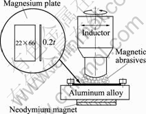
Fig.4 Experimental setup for MAP of AZ31 magnesium alloy
Table 1 Experimental conditions

3.3 Design of experiments (DOE) for MAP of AZ31
The DOE provides means how to perform efficiently experimentation to evaluate the effect of the process parameters on the obtained results. One of the most famous DOEs is Taguchi��s method which has advantages to reduce the number of experiments by the orthogonal array and to evaluate more easily the relation among the process parameters through a signal-to-noise (S/N) ratio[10]. So, in this study, Taguchi��s DOE was performed to evaluate the effect of the process parameters on the surface roughness after the MAP. Table 2 lists the parameters and levels used in this experiment. The ranges of these parameters were selected on the basis of preliminary experiments. Table 3 shows an orthogonal array table for L9(34) applied to this study.
Table 2 Parameters and levels used in experiments
4 Results and discussion
4.1 Effect of magnetic force improvement
Fig.5 presents the change of the surface roughness in Ra after the MAP without and with the permanent
Table 3 Orthogonal array table for L9(34)
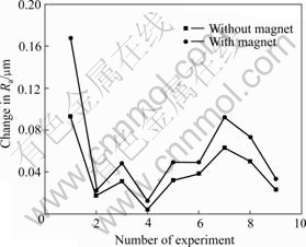
Fig.5 Change in Ra after MAP without magnet and with magnet
magnet under the same experiments. As shown in Fig.5, the MAP of the AZ31 magnesium alloy with the permanent magnet had better surface roughness improvement than that without the permanent magnet. And better machining efficiency of the MAP for the magnesium alloy with the permanent magnet was verified.
4.2 Parameter optimization
Table 4 lists the measured experimental results and calculated S/N ratios. The performance measure in this study was the change in the surface roughness before and after the MAP. The change in the surface roughness is a ��higher-is-the-better�� type of quality characteristic in Taguchi method. So, the ��higher-is-the-better�� characteristic was used to calculate the S/N ratio. The loss function for this characteristic is given as follows.
![]() (1)
(1)
where Lij is the loss function of the ith performance characteristic in the jth experiment[11]. The corresponding S/N ratio is given by
��ij = -10 lg(Lij) (2)
Fig.6 presents the influence of process parameters on the MAP of the AZ31 magnesium alloy. From Fig.6, it can be observed that the parameters of A, C and D affect the change of surface roughness. And it shows that the level 3 of parameter A(A3) and levels 1 of parameters of B(B1), C(C1) and D(D1) provide the optimum result to produce best surface for the MAP of the AZ31 magnesium alloy.
Analysis of variance (ANOVA) as listed in Table 5 is performed to determine which parameter affects significantly the surface roughness. The parameter B is pooling as error data. The analytic result indicates that the parameter C (rotational speed) affects significantly the surface roughness. It means that the tangential force on the workpiece is highly changed when the rotational speed is increased or decreased. Since the magnetic force generated by the permanent magnet draws strongly the magnetic abrasives near the workpiece, the higher rotational speed is needed to remove effectively the material.
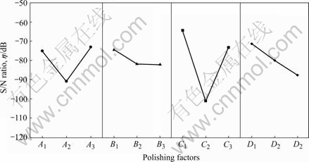
Fig.6 Influences of parameters on MAP of AZ31 magnesium alloy
Table 4 Experimental results and calculated S/N ratio
Table 5 ANOVA for process parameters
5 Conclusions
In this study, the improving strategy of the magnetic force using the permanent magnet was applied for the MAP of the AZ31 magnesium alloy. And to evaluate effect of process parameters on the result of the MAP, the experiments were performed under the guide of the DOEs. The following conclusions were drawn:
1) When the permanent magnet was installed on the opposite side of the AZ31 magnesium alloy, the magnetic density flux with the permanent magnet was higher than that without the permanent magnet. And the change in the surface roughness after the MAP with permanent magnet also was better than that without.
2) The optimal conditions for the MAP of the AZ31 magnesium alloy were the level 3 of parameter A (2.0A) and level 1 of parameters B (1.0 mm), C (800 r/min) and D (0.7 g).
3) The parameter C (rotational speed) significantly affected the improvement of the surface roughness after the MAP of the AZ31 magnesium alloy.
Acknowledgement
This research was financially supporting by the Ministry of Education, Science Technology (MEST) and Korea Industrial Technology Foundation (KOTEF) through the Human Resource Training Project for Regional Innovation (Design and Process Optimization of Reactor System for Pre-Polymer Production, 20070130134117). And also this work was supported by Pukyong National University Research Fund in 2006 (Effect Evaluation and Optimization of Process Parameters on Magnetic Abrasive Polishing, PKS-2006-022).
References
[1] International Magnesium Association Technical Committee. Machining of magnesium and magnesium and magnesium alloys [M]// Metals Handbook. 1989, 16: 820-830.
[2] SOHN K Y. The effect of heat treatment and extruded Mg-Al-Zn alloy [J]. Material Science Forum, 2003, 419/422: 135-140.
[3] CHINO Y, KIMURA K, MABUCHI M. Twinning behavior and deformation mechanisms of extruded AZ31 Mg alloy [J]. Mater Sci Eng A, 2008, 486: 481-488.
[4] TOMAC N, TONNESSEN K. Formation of flank build-up in cutting magnesium alloys [J]. Ann CIRP, 1991, 40(1): 79-82.
[5] ARAI M, SATO S, OGAWA M, SHIKATA H. Chip control in finish cutting of magnesium alloy [J]. Journal of Material Process Technology, 1996, 62: 341-344.
[6] TRENT E M, WRIGHT P K. Metal cutting [M]. USA: Butterworth- Heinemann, 2000.
[7] JAIN V K, KUMAR P, BEHERA P K, JAYWAL S C. Effect of working gap and circumferential speed in the performance of magnetic abrasive finishing process [J]. Wear, 2001, 250: 384-390.
[8] SINGH D K, JAIN V K, RAGHURAM V, KOMANDURI R. Analysis of surface texture generated by a flexible magnetic abrasive brush [J]. Wear, 2005, 259: 1254-1261.
[9] SINGH D K, JAIN V K, RAGHURAM V. Parametric study of magnetic abrasive finishing process [J]. Journal of Material Processing Technology, 2004, 149: 22-29.
[10] KWAK J S, KIM I K, HA M K, KIM Y S. Optimization strategies of grinding parameters for metal matrix composites by design of experiments and genetic algorithm [C]// International Conference on Leading Edge Manufacturing in 21st Century. 2005: 607-612.
[11] SINGH S, SHAN H S, KUMAR P. Parametric optimization of magnetic-field-assisted abrasive flow machining by the Taguchi method [J]. Quality and Reliability Engineering International, 2002, 18: 273-283.
(Edited by HE Xue-feng)
Corresponding author: J. S. KWAK; E-mail: jskwak5@pknu.ac.kr
