

J. Cent. South Univ. (2021) 28: 2091-2104
DOI: https://doi.org/10.1007/s11771-021-4755-1

Mechanical behaviors of cross roller bearings with raceway roundness error
HUANG Jian(�ƽ�), LI Chao-yang(���), CHEN Bing-kui(�±���)
State Key Laboratory of Mechanical Transmission, Chongqing University, Chongqing 400044, China
 Central South University Press and Springer-Verlag GmbH Germany, part of Springer Nature 2021
Abstract:
Taking the raceway roundness error into account, mechanical characteristics of cross roller bearings (CRBs) were investigated. A static analysis model of CRBs considering the raceway roundness error was established. Based on this model, the rotational accuracy and load distribution of CRBs under constraints of geometry and external loads were derived. The fatigue life of CRBs with roundness error was calculated by applying Palmgren-Miner linear cumulative damage theory. The influence of inner and outer raceway roundness error on the performance of the CRBs, such as rotational accuracy, load distribution, and fatigue life, was studied through the analysis of examples. The results indicate that the influence of roundness error on the rotating inner raceway is more significant than that of roundness error on the nonrotating outer raceway. The roundness error on the rotating inner raceway always degrades the performance of CRBs. However, a proper roundness error on the nonrotating outer raceway can reduce the loads acting on the rollers and thus improve the fatigue life of CRBs. The effect of the roundness error amplitude on the bearing performance is ordinal, whereas the effect of the roundness order on the bearing performance is not in order.
Key words:
cross roller bearings; roundness error; load distribution; rotational accuracy; fatigue life��
Cite this article as:
HUANG Jian, LI Chao-yang, CHEN Bing-kui. Mechanical behaviors of cross roller bearings with raceway roundness error [J]. Journal of Central South University, 2021, 28(7): 2091-2104.
DOI:https://dx.doi.org/https://doi.org/10.1007/s11771-021-4755-11 Introduction
Cross roller bearings (CRBs) are compact bearings with their rollers alternately crossed at right angles to each other between inner and outer rings. Therefore, CRBs can take loads from any directions at the same time such as radial, thrust, and moment loads. CRBs are widely used in rotating parts such as industrial robots, machine tools, medical equipment, and measuring instruments, which require compactness, high rigidity, and high rotational accuracy. The rotational accuracy and running safety of the machinery are highly determined by the characteristics of CRBs.
For bearings, the geometric error is one of the most common problems encountered in engineering applications and manufacturing processes [1]. Even if the most advanced processing system is used in processing, geometric defects are inevitable. The geometric defect will critically alter the interaction of bearings. Therefore, the rotational and fatigue life of rolling bearing will be influenced. The geometric error degrades the mechanical performance of rolling bearing [2]. Therefore, it is desirable to investigate the mechanical behavior of cross roller bearings with geometric error.
In recent studies, HARSHA et al [3] proposed an analytical model to predict non-linear dynamic responses in a rotor-bearing system due to surface waviness. SHAH et al [4] analyzed the vibrations of deep groove ball bearings with waviness error on raceways. HALMINEN et al [5] presented a model for the analysis of the friction loss of a touchdown bearing with surface waviness. WANG et al [6] presented a numerical study on the effect of surface waviness on the performance of aerostatic journal bearings. ZHANG et al [7] established a new model to predict the radial error motions of hydrostatic journal bearings considering roundness error. RAFSANJANI et al [8] proposed an analytical model to investigate the nonlinear dynamic performance of rolling element bearing systems including surface defects. PATIL et al [9] presented an analytical model to study the effect of the localized defect on vibrations associated with ball bearing. PETERSEN et al [10, 11] presented an analytical formulation of the load distribution and varying effective stiffness of a ball bearing assembly with a raceway defect. YU et al [12] presented a calculation for cylindrical roller bearings considering dimension and form errors. GONCZ et al [13] presented a new computational model for the determination of load distribution and static load capacity of three-row roller slewing bearings. POTOCNIK et al [14] proposed a computational method for calculating contact load distribution and static capacity of large double row slewing ball bearing. CHEN et al [15] analyzed the effects of raceway roundness and roller diameter errors on the radial clearance and runout of cylindrical roller bearing. MA et al [16] studied the influences of roller diameter errors on the mechanical performance of spherical roller bearings. CHEN et al [17] studied the effects of off-sized balls and raceway error on the mechanical performance of angular contact ball bearings. TONG et al [2] investigated the effects of roller diameter error on stiffness and fatigue life of tapered roller bearings. YE et al [18] established a model to analyze the load distribution and contact stress of a high-speed roller bearing considering the titled misalignment between inner and outer raceways. XING et al [19] analyzed the mechanical performance of spherical roller bearings considering the angular and centroidal misalignments between the inner and outer rings. WARDA et al [20] analyzed the effect of ring misalignment on the fatigue life of a cylindrical roller bearing. TONG et al [21] presented an improved formula to provide the running torques for tapered roller bearings with angular misalignment between inner and outer raceways. AITHAL et al [22] analyzed the effect of manufacturing errors on load distribution in large diameter slewing bearings of fast breeder reactor rotatable plugs. TONG et al [1] studied the mechanical behavior of tapered roller bearing considering the geometric error of raceway. LIU et al [23] proposed an analytical method for calculating the friction torque of a needle roller with roundness error.
The above research mainly focused on the influences of the misalignment of the raceway, the surface waviness, and the diameter error of rollers on the dynamic performance of the rolling bearing. In practice, the roundness error is also a major geometric error of the bearings [23]. The geometrics of the roundness error is very different from that of the waviness error. Therefore, the influence of the roundness error on the mechanical behavior of the CRB should be different from that of the waviness error. However, there are few reports on the mechanical properties of CRBs considering the roundness error of raceway.
Therefore, the mechanical behavior of CRBs with raceway roundness error was investigated in this study. A static analysis model of CRBs considering the roundness error of the inner and outer raceways was presented. Based on the static analysis model, the rotational accuracy and load distribution of CRBs were derived. Subsequently, the formula for calculating fatigue life of CRBs considering raceway roundness error was developed by using Palmgren-Miner linear cumulative damage theory. Finally, the effects of the raceway roundness error on the rotation accuracy, load distribution, and fatigue life of CRBs were studied.
2 Computational model
The raceway roundness error changes the contact position and the contact loads between roller and raceway. Furthermore, the rotational accuracy and fatigue life of CRB are affected. A static analysis model for analyzing the mechanical behavior of CRBs considering the raceway roundness error is proposed in this section. The load distribution and rotational accuracy of CRBs are calculated. And then, the calculation formula of fatigue life of CRBs considering raceway roundness error is derived by using Palmgren-Miner linear cumulative damage theory.
2.1 Macro-geometry and kinematics equations
As shown in Figure 1, CRBs are the main component of the inner ring, outer ring, and rollers. Different from general cylindrical roller bearings, there are four raceways in CRBs. The rollers are alternately cross at right angles to each other between inner and outer raceways. In this work, the rollers are divided into two groups by the direction of the loads between roller and raceway. It is assumed that the rollers bearing the load between raceways 1 and 2 are classified as row I and the others belong to row II.
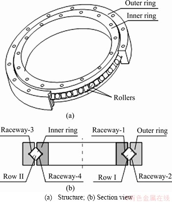
Figure 1 Brief overview of CRB:
Figure 2 shows a diagram of a CRB with coordinate systems. It is assumed that the outer ring of the CRB is fixed. The inner ring is subjected to external loads. The external loads are defined as combined load vector F:
 (1)
(1)
where Fx, Fy and Fz are the static forces applied to the radial (x, y) and axial (z) directions, and Mx and My are the static moment loads around the x and y axes.
The relative displacements and rotations between inner and outer rings are defined as d:
 (2)
(2)
where ��x, ��y, ��z, are the relative displacements in the x, y and z directions, and ��x and ��y are the relative rotations around the x and y axes.
As shown in Figure 2, the inner ring rotates around the z-axis at the angular velocity ��in. The cage rotates with the rotation of the inner ring. According to the theory of HARRIS et al [24], the angular velocity of the cage is given as:
 (3)
(3)
where D is the diameter of the roller; dm is the pitch diameter of the bearing; �� is the contact angle. At time t, the rotation angle of the cage around the z-axis is:
 (4)
(4)
To determine the movement of each roller, the angle positions ��ij of roller j in row i at time t are given by:
 (5)
(5)
where Z is the number of rollers of each row.
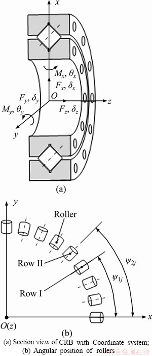
Figure 2 Coordinate systems of CRB:
2.2 Roundness error of raceways
The geometric error of raceway is inevitable in manufacturing processes. The cause of roundness error of the inner and outer raceway of CRBs is very complicated, including the runout of machine tool spindle, installation error of bearings, temperature variation, stress caused by load, etc. As shown in Figure 3, the roundness on the raceways is generally observed in the shape of peaks and valleys of varying height. The roundness error of raceway along the circumferential direction can be decomposed into harmonic waves of different frequencies based on the Fourier transform [7]:
 (6)
(6)
where ��ij is the angular position of roundness error; �� is the roundness order; A�� is the amplitude of the ��th roundness on the raceway; q is the total roundness number and
 is the initial angular position of roundness error.
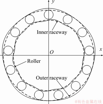
Figure 3 Illustration of bearing with roundness error
The inner ring rotates around the z-axis at an angular velocity ��in. It is assumed that the roller is in pure rolling motion. So, the roller is always in contact with the inner raceway. The roundness error of the inner raceway at roller j in row i can be expressed in the following form:
 (7)
(7)
where  is the amplitude of the roundness error on the inner raceway; �� is the roundness order; q is the total roundness number;
  is the angular position of inner raceway roundness error for the roller j in row i;
  is the initial angular position of the roundness error.
The angle positionis given as:
 (8)
(8)
Similarly, the roundness error on the outer raceway can be expressed as
 (9)
(9)
where  is the amplitude of the roundness error on the outer raceways; is the angular position of the outer raceway roundness error for the roller j in row i and
 is the initial angle of the roundness error.
The outer ring is fixed. Therefore, the contact angle  is equal to the angle positions
  of rollers, that is,
 (10)
(10)
2.3 Contact deformations and forces
The contact deformation between the roller and raceway is composed of three components: 1) ��ij due to the relative displacement between the inner ring and outer ring, 2) the deformation due to roller tilt at roller angle location j in row i, and 3) Ck due to the crown drop of the roller.
When CRBs are subjected to external loads, the relative displacements and angle displacements between the inner and outer rings are defined as d=[��x, ��v, ��z, ��x, ��v]T. The relative displacement of the two raceways at the angle position of roller j in row i can be calculated as

 (11)
(11)
where Pd is the radial clearance; ��xcos��cos��ij+ ��vcos��sin��ij+c1��zsin�� is the relative displacement generated by the translational displacement of the inner ring; c1dm(��xsin��ij-��vcos��ij)/2 is relative displacement generated by the angular displacement of the inner ring; and dij(��ij)+dij(��ij) is the relative displacement generated by roundness error. The coefficient c1 is givens as follows:
 (12)
(12)
The contact between roller and raceway of CRBs is a typical line contact problem. To consider the accuracy and the fastness, slicing technique has frequently been used [25]. In the present study, the roller is sliced into n laminae as shown in Figure 4. When there is an angular displacement between the inner and outer rings, the contact deformation at each lamina is not uniform. The angular misalignment between the roller and raceway at roller angle location j in row i is ��ij=��xsin��ij-��vcos��ij. For the kth (1��k��n) lamina, the distance from the lamina to the center of the roller is:
 (13)
(13)
where l is the effective length of rollers; the deformation caused by angular misalignment is the product of inclined angle and the distance from the lamina to the center of the roller. The contact deformation ��ijk at the kth lamina is given by:
 (14)
(14)
where ck is the crown drop of the roller. According to standard ISO/TS 16281 [26], the crown drop between the crowned profile and cylindrical profile of the lamina k is expressed as:
 (15)
(15)
The load-deflection equation of each lamina is:
 (16)
(16)
Here, the spring constant cs can be described as:
 (17)
(17)
For each lamina, the contact stiffness is determined by the length of the lamina. It is generally considered that they are independent of each other. The deformation and contact load of each lamina have no effect on other laminae [27]. The total contact force between roller and raceway is determined by the summation of a load of each roller lamina:
 (18)
(18)
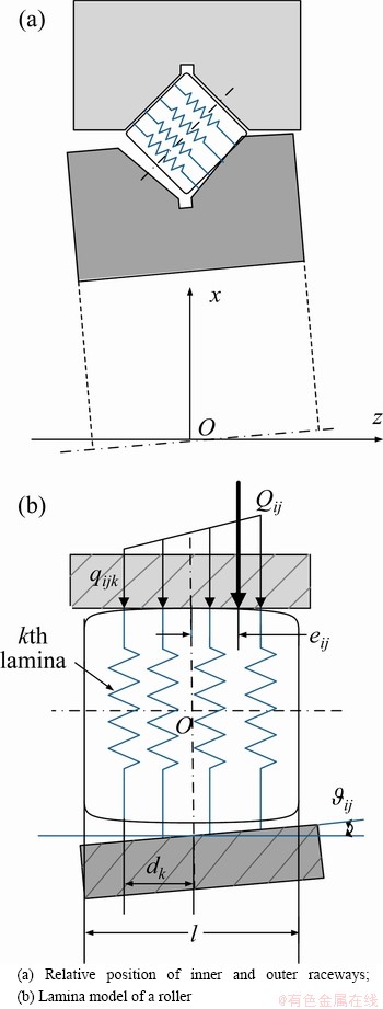
Figure 4 Contact deformation of rollers and raceways:
2.4 Rotational accuracy and load distribution
The rotational accuracy of the bearing depends on the geometric accuracy of bearing components [12]. The geometric error of the CRBs raceway causes the change of contact deformation between the roller and the raceway. So, the rotational accuracy and load distribution are affected.
When the geometric error and elastic deformation between the roller and raceways are not considered, the rotation center of the inner ring is always in a straight line. However, owing to the geometric error and the elastic deformation, the inner ring will be displaced or tilted. This will affect the rotational accuracy of CRBs. In this paper, the outer ring is fixed and the inner ring is subjected to external loads. Under the load, the inner ring has relative displacements and angle displacements. Thus, CRB finally reaches a stable state.
The formula for the contact load of each roller is derived in the last section. To obtain the static equilibrium of external loads, the load on each lamina is transformed into point force (Qij) as shown in Figure 4(b). The value of the point force is the summation of forces acting on each lamina, whose location (the load eccentricity) is determined by the following relation:
 (19)
(19)
where the load eccentricity eij is the distance between the point load vector line of action and roller center. Considering forces due to all the rollers in two rows, the sum of forces and moment loads acting on the inner ring can be obtained through Eq. (20). And it should be balanced coordinately with external loads F.
 (20)
(20)
Equation (20) is a nonlinear equation, in which the unknowns are the vector [��x, ��v, ��z, ��x, ��v]. Numerical methods such as Newton��s method are used to obtain the displacement and angle displacement of the inner ring. The bearing displacements and rotations that solve Eq. (20) are defined as:
 (21)
(21)
The displacement and angle displacement of the inner ring is derived. Substituting the displacement  into Eqs. (11)-(14), the roller-raceway contact deformation at each roller lamina can be obtained as:

 (22)
(22)
Substituting the contact deformation into Eqs. (16)-(18), and the load of rollers is obtained as:
 (23)
(23)
2.5 Fatigue life
The fatigue life model was first proposed by LUNDBERG et al [28]. It was adopted by the International Standards Organization in Standard ISO 281/1 [29]. However, this model ignores the bearing clearance effect. And it assumes that the raceway of bearings is an ideal circle without considering the raceway error. Therefore, this method is not applicable in this paper. According to HARRIS theory [24], the fatigue life of a roller�Craceway line contact subjected to normal load Q can be estimated by:
 (24)
(24)
where L is in millions of revolutions, and Qc is the basic dynamic load of bearing raceway. It can be obtained by:
 (25)
(25)
where the upper signs refer to the inner raceway contact and the lower signs refer to the outer raceway contact; �� is the parameter related to the structure of bearing, defined as ��=Dcos��/dm.
For rotated inner raceway, the equivalent contact load is determined as:
 (26)
(26)
The equivalent loading of a nonrotating raceway is given by:
 (27)
(27)
The life of rotating and nonrotating raceway is:
 (28)
(28)
In this paper, the outer ring is fixed. So, subscripts u and v represent inner and outer raceways respectively. Because there are two rows of rollers, the fatigue life of CRBs with line contact can be calculated from the following relation:
 (29)
(29)
where Lu1 and Lu2 are the life of rotating inner raceways in contact with rollers of row I and row II, respectively; Lv1 and Lv2 are the lives of nonrotating outer raceways in contact with rollers of row I and row II, respectively.
When geometric errors in the rotating raceway exist, the internal load distribution varies with time. According to Ref. [2], the loaded CRB with geometric errors can be treated as a CRB under time-varying loads. In a rotation period, the varying load distribution of the bearing is divided into various discretized load cases, captured at each certain interval time. By the Palmgren�CMiner linear cumulative damage theory, the fatigue life of CRB with geometric errors can be obtained as:
 (30)
(30)
where N is the total number of load cases used to calculate the fatigue life L10
3 Results and discussion
The calculation program is implemented based on the above method. The calculation has been implemented with MATLAB 2017a on a Windows 10 Intel(R) Xeon(R) Silver 4110 CPU @2.10 GHz with 64 GB RAM. In this study, the load vector F is given as an input parameter. The displacement vector d is unknown and needs to be determined. To satisfy the requirement of static equilibrium, the equilibrium equations of the bearing are solved based on Newton-Raphson method. The external load acts on the inner ring. The angular speed of the inner ring is ��in=10 r/min. The parameters of CRB used in this section are listed in Table 1. The radial clearance Pd is set as zero. The influences of roundness error order and amplitude on rotational accuracy, load distribution, and fatigue life of CRBs are analyzed.
3.1 Model verification
To verify the accuracy of the analysis model in this study, a finite element model was created. The overall FE model of the bearing was established as shown in Figure 5. The inner and outer rings are meshed using SOLID185(3-D 8-node structural solid). The roller is simplified as spring element COMBIN 39, which has the same displacement-contact force characteristics as in the actual contact. These springs are defined as non-linear elastic connectors in compression with no stiffness in tension. The outer ring of the bearing is fixed. The external moment load is applied to the inner ring through a reference point, which is coupled with the mounting plane of the inner ring.
Table 1 Parameters of CRB
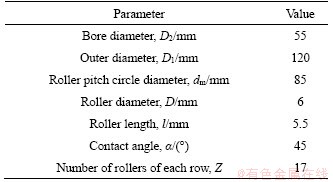
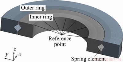
Figure 5 Section view of FEM model of CRB
Figure 6 shows the load distribution of CRB with moment load Mv=240 N��m. The contact load calculated by FEM is compared with that obtained by the static analysis model of this study. As shown in Figure 6, the load distribution predicted by the FEM is in good agreement with that predicted by the proposed method. The angle range of rollers bearing load is consistent. The maximum load of the rollers obtained by the proposed method is 940.6 N. The maximum load of rollers obtained by FEM is 926.9 N. The little discrepancy for the two dealings shows that the present method can be used in the following analysis.
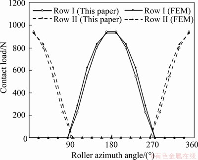
Figure 6 Load distribution of CRB without roundness error when Mv=240 N��m
3.2 Effect of inner raceway roundness error
3.2.1 Rotational accuracy
Figure 7 shows the influence of inner raceway roundness error on the rotational accuracy of CRB. The moment load is Mv=240 N��m. As shown in Figure 7(a), the angular displacement of the inner ring is stable at 1.05 arc/min when there is no geometric error. The angular displacement of the inner ring fluctuates periodically when there is a roundness error on the inner raceway. Thus, the rotational accuracy of the CRB is decreased. With the growth of the amplitude of inner raceway roundness error from 2 to 8 ��m, the amplitude of the fluctuation increases obviously. When the amplitude of roundness error is 0.008 mm, the maximum and minimum angle displacements of the inner ring are 1.48 and 0.64 arc/min respectively. The fluctuation of angle displacements is 0.84 arc/min. In Figure 7(b), the amplitude of the roundness error of the inner raceway is 2 ��m. The effect of the roundness order is not in order. When the roundness order is 2, the variation of angular displacement is the largest. Because the distribution of internal load in the bearing without roundness error is similar to the distribution of roundness error of raceway along the circumferential direction. During the rotation of the inner ring, the angular range of the positive or negative roundness error may coincide with the extent of the load zone, which causes a violent fluctuation of the angular displacement. For other roundness error, the period of the roundness error is greater than that of load distribution. Therefore, the fluctuation of the angular displacement is much smaller.
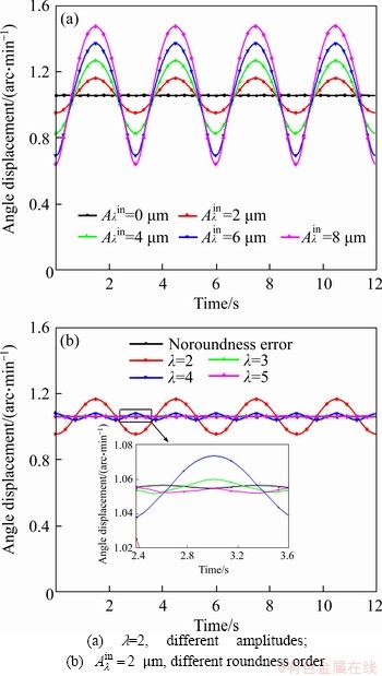
Figure 7 Angle displacement of CRB with inner raceway roundness error:
3.2.2 Load distribution
Figure 8 shows the load distribution of the CRB without geometric error. The moment load of CRB is Mv=240 N��m. As shown in Figure 8(a), half of the rollers of each row bear load. For the rollers of row I, the load along with the raceway ranges from 90�� to 270��. For the rollers of row II, the load along the raceway ranges from 0 to 90��, 270�� to 360��. The maximum load is 940.6 N. Figure 8(b) shows the loads acting on rollers of row II during the rotation of the inner ring. As shown in this graph, the loads acting on the rollers vary periodically; No. 1, No. 7, and No. 10 rollers are taken as examples, and the blue line represents the load condition of the remaining rollers. Compared with the load variations of the three rollers, the load variations of each roller are the same during the rotation of the inner ring.
As shown in Figure 9, the amplitude of the roundness error on the inner raceway is 2 ��m. The roundness order is 2 and the initial angle of the roundness error is 0. Within the range of 45��-135�� and 225��-270��, the amplitude of the roundness error on the inner raceway is negative.
Figure 9(b) depicts the influence of inner raceway roundness error on the load distribution of CRB. The solid line indicates the load acting on the rollers of row one, and the dotted line indicates the load acting on the rollers of row two. Within the range of 45��-135�� and 225��-270��, the loads acting on the rollers are reduced when roundness error exists in the inner raceway. Because the amplitude of the roundness error is negative, the contact deformation between rollers and raceway is reduced. However, the loads acting on the other rollers are increased. The maximum load acting on the rollers increases from 940.6 to 1053.9 N.
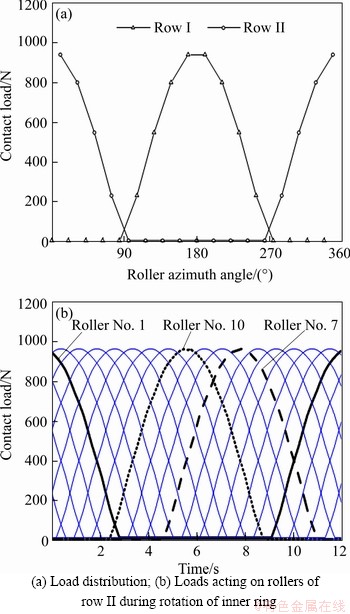
Figure 8 Load distribution of CRB without roundness error:
Figure 9(c) shows the contact loads acting on the rollers of row II during the rotation of the inner ring. Due to the inner raceway roundness error, the roller-raceway contact deformation of each roller is not the same. Therefore, the load variations of the rollers during the rotation of the inner ring are different. The maximum load acting on roller Nos. 1, 7 and 10 are 1053.9, 878.4 and 1051.6 N.
3.2.3 Fatigue life
Figure 10 shows the influence of inner raceway roundness error on the fatigue life of CRB. It can be observed that the roundness error of the inner raceway always reduces fatigue life. In Figure 10(a), the roundness order is 2. The fatigue life decreases with the increase of the amplitude of inner raceway error. Under the moment load of My=240 N��m, when the amplitude of the error is 0, the maximum fatigue life is 1.03��108 revolutions. When the amplitude of the error increases to 8 ��m, the fatigue life reduces to 0.31��108 revolutions. And also, the influence of the roundness error decreases with the increase of moment load. In Figure 10(b), the amplitude of the roundness is 2 ��m. The fatigue life of CRB with different roundness orders all decreased. However, the effect of the roundness order is not in order. Under the moment load My=240 N��m, when the inner raceway roundness order increases from 2 to 5, the fatigue life is 99.2��106, 85.8��106, 82.1��106, 81.4��106 revolutions, respectively. When ��=4 and ��=5, although the order is different, the influence of the error on fatigue life is almost the same. The fatigue life is mainly determined by the contact load of the raceway. Although the roundness error is different, the equivalent load of the raceway is not much different from that considering the load distribution under different position angles.
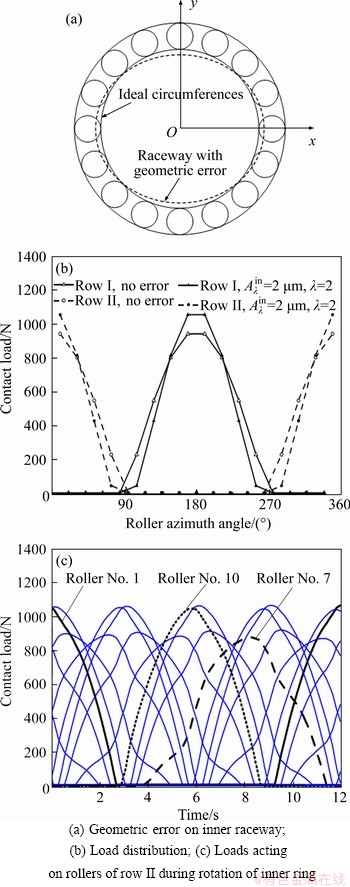
Figure 9 Load distribution of CRB with inner raceway roundness error  ��m, ��=2):
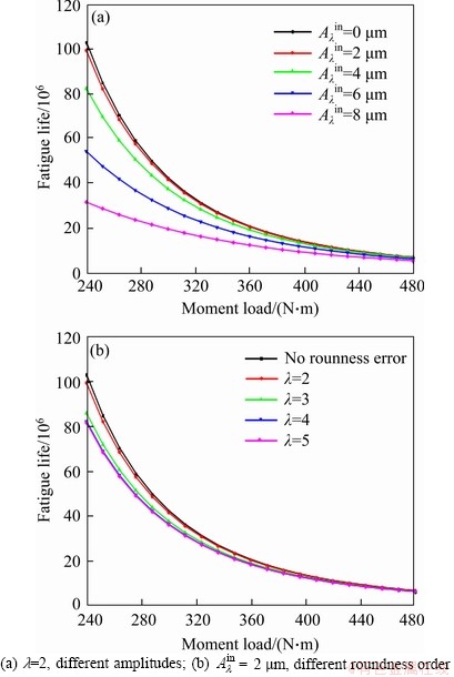
Figure 10 Fatigue life of CRB with inner raceway roundness error:
3.3 Effect of outer raceway roundness error
3.3.1 Rotational accuracy
Figure 11 shows the influence of outer raceway roundness error on the rotational accuracy of CRB with a moment load My=240 N��m, the roundness order is 2, the angular displacement of the inner ring is the smallest when there is no roundness error. The angle displacement increases with the growth of the amplitude of roundness error and is stable at 1.05 arc/min. Unlike Figure 4(a), the angle fluctuation of the inner ring is very small. Because the outer ring is fixed, the angle fluctuation mainly results from the rotation of the rollers. In Figure 11(b), the amplitude of the roundness error is 2 ��m. With the growth of roundness order, the period of the fluctuation of angle displacement remains unchanged. When the roundness order is 2 or 3, the angle displacement increases. When the roundness order is 5, the angle displacement decreases. When the roundness order is 4, the angular displacement is almost the same with the angular displacement of the inner ring without raceway error.
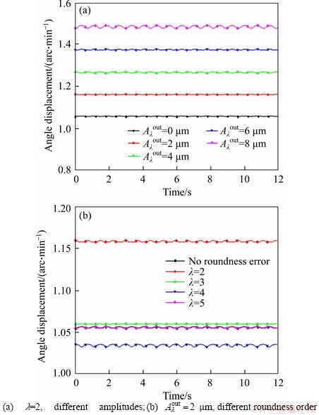
Figure 11 Angle displacement of CRB with outer raceway roundness error:
The roundness error changes the initial distance between the roller and the raceway, thereby affecting the load distribution of the bearing. For different roundness errors, the distribution and amplitude of the roundness errors along the circumference of the raceway are different. Therefore, the angular displacement of the inner ring is different when the bearing with different roundness errors reaches static balance.
3.3.2 Load distribution
As shown in Figure 12, the amplitude of the roundness error on the outer raceway is 2 ��m. The roundness order is 2 and the initial angle of roundness error is 0. Within the range of 45��-135�� and 225��-270��, the amplitude of the roundness error on the outer raceway is positive.
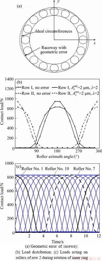
Figure 12 Load distribution of CRB with outer raceway roundness error  ��m, ��=2):
Figure 12(b) depicts the influence of outer raceway roundness error on load distribution. The solid line indicates the loads acting on the rollers of row I, and the dotted line indicates the loads acting on the rollers of row II. Because the amplitude of the roundness error within the range of 135��-225�� is negative, the loads acting on these rollers are reduced. However, within the range of 45��-135�� and 225��-270��, more rollers bear the external load. The maximum load acting on the rollers decreases from 940.6 to 828.6 N.
Figure 12(c) expresses the contact load variation while the inner ring is rotating. The loads are reduced because of the roundness error of the outer raceway. It is similar to Figure 8 that the loads on the roller vary periodically during the rotation of the inner ring. The variation process of the contact load is the same for every roller. Compared with Figure 9(c), the influence of the roundness error of the outer raceway on the load distribution is smaller. This is because the outer ring is fixed. The irregular fluctuation of the load is mainly caused by the rotation of roundness error.
3.3.3 Fatigue life
Figure 13 shows the influence of outer raceway roundness error on the fatigue life of CRB. In Figure 10(a), the roundness order is 2 and the initial angle of the roundness error is 0. It can be observed that the roundness error of the outer raceway does not always reduce fatigue life. The roundness error is not always harmful to the fatigue life of CRB. When the amplitude of the roundness error is 2 ��m, the maximum fatigue life is 125.31��106 revolutions. When the amplitude of the roundness error is 4 ��m, the maximum fatigue life is 115.66��106 revolutions; when there is no geometric error, the maximum fatigue life is 103��106 revolutions. It is consistent with the load distribution in Figure 12. Due to the roundness error of the outer raceway, more rollers bear the load and the maximum load of the rollers is decreased. Therefore, the fatigue life is increased. In Figure 13(b), the roundness amplitude is 2 ��m. When the roundness order is 3 or 5, the bearing life is reduced. When ��=4, the influence of the roundness error on the fatigue life is quite little.
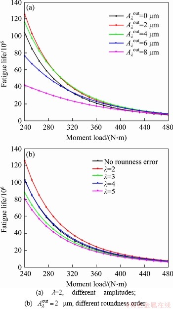
Figure 13 Fatigue life of CRB with outer raceway roundness error:
The bearing fatigue life is mainly determined by the roller-raceway contact. The roundness error will change the distribution of load among the rollers, thereby affecting the fatigue life of the bearing. The effects of roundness errors at different amplitudes and wavelengths are different, thus leading to different effects on fatigue life. In Figure 13(a), the roundness error  ��m,
��m,  4 ��m) causes more rollers to bear the load and thus reduces the load of the roller; therefore, the fatigue life is increased. In Figure 13(b), the wavelengths of the roundness error are different; therefore, the load varies with the wavelength, which leads to a change of fatigue life.
4 Conclusions
This paper presents a static analysis model of CRBs considering the roundness error of raceways. The effects of the raceway roundness error on the rotational accuracy, load distribution, and fatigue life of CRBs are studied. From the investigation, the following conclusions can be drawn:
1) The angular displacement of the inner ring fluctuates periodically when there is a roundness error on the rotating raceway. The fluctuation increases with increase of the roundness error amplitude. There is no fluctuation when a roundness error exists in the nonrotating raceway, but the mean value of angle displacement deviates from the initial value. The variation of angle displacement increases with the amplitude increase.
2) The load distribution becomes irregular when there is a roundness error on the rotating raceway. However, although the load distribution is altered when there is a roundness error on the nonrotating raceway, the change process of the contact load is the same for every roller.
3) The roundness error on the rotating raceway always reduces the fatigue life of CRB. The proper roundness error on the nonrotating raceway can make more rollers bear the load, and thus, the load on rollers is reduced. Consequently, the fatigue life of CRB is improved.
4) Under the same roundness order, the influence of the amplitude of roundness error on the fatigue life and rotational accuracy is ordinal. However, under the same amplitude, the effect of the roundness order is not in order.
5) The influence of roundness on the rotating raceway is more significant than that of roundness on the nonrotating raceway. During the manufacturing process, the tolerance of the rotating raceway needs to be strictly controlled.
Contributors
The overarching research goals were developed by CHEN Bing-kui and LI Chao-yang. LI Chao-yang and HUANG Jian established the models and analyzed the calculated results. CHEN Bing-kui and LI Chao-yang provided funding acquisition. HUANG Jian and LI Chao-yang conducted the literature review and wrote the first draft of the manuscript. HUANG Jian edited the draft of manuscript.
Conflict of interest
HUANG Jian, LI Chao-yang, and CHEN Bing-kui declare that they have no conflict of interest.
References
[1] TONG V C, HONG S W. Characteristics of tapered roller bearing with geometric error [J]. International Journal of Precision Engineering and Manufacturing, 2015, 16(13): 2709-2716. DOI: 10.1007/s12541-015-0346-0.
[2] TONG V C, HONG S W. Study on the stiffness and fatigue life of tapered roller bearings with roller diameter error [J]. Proceedings of the Institution of Mechanical Engineers, Part J: Journal of Engineering Tribology, 2016, 231(2): 176-188. DOI: 10.1177/1350650116649889.
[3] HARSHA S P, SANDEEP K, PRAKASH R. Non-linear dynamic behaviors of rolling element bearings due to surface waviness [J]. Journal of Sound and Vibration, 2004, 272(3-5): 557-580. DOI: 10.1016/s0022-460x(03)00384-5.
[4] SHAH D S, PATEL V N. Theoretical and experimental vibration studies of lubricated deep groove ball bearings having surface waviness on its races [J]. Measurement, 2018, 129: 405-423. DOI: 10.1016/j.measurement.2018.07.031.
[5] HALMINEN O, ACEITUNO J F, ESCALONA J L, SOPANEN J, MIKKOLA A. A touchdown bearing with surface waviness: Friction loss analysis [J]. Mechanism and Machine Theory, 2017, 110: 73-84. DOI: 10.1016/ j.mechmachtheory.2017.01.002.
[6] WANG Xin-kuan, XU Qiao, WANG Bao-rui, ZHANG Lian-xin, YANG Hong, PENG Zhi-ke. Effect of surface waviness on the static performance of aerostatic journal bearings [J]. Tribology International, 2016, 103: 394-405. DOI: 10.1016/ j.triboint.2016.07.026.
[7] ZHANG Peng-hai, CHEN Yao-long, LIU Xiao-ting. Relationship between roundness errors of shaft and radial error motions of hydrostatic journal bearings under quasi-static condition [J]. Precision Engineering, 2018, 51: 564-576. DOI: 10.1016/j.precisioneng.2017.10.012.
[8] RAFSANJANI A, ABBASION S, FARSHIDIANFAR A, MOEENFARD H. Nonlinear dynamic modeling of surface defects in rolling element bearing systems [J]. Journal of Sound and Vibration, 2009, 319(3-5): 1150-1174. DOI: 10.1016/j.jsv.2008.06.043.
[9] PATIL M S, MATHEW J, RAJENDRAKUMAR P K, DESAI S. A theoretical model to predict the effect of localized defect on vibrations associated with ball bearing [J]. International Journal of Mechanical Sciences, 2010, 52(9): 1193-1201. DOI: 10.1016/j.ijmecsci.2010.05.005.
[10] PETERSEN D, HOWARD C, PRIME Z. Varying stiffness and load distributions in defective ball bearings: Analytical formulation and application to defect size estimation [J]. Journal of Sound and Vibration, 2015, 337: 284-300. DOI: 10.1016/j.jsv.2014.10.004.
[11] PETERSEN D, HOWARD C, SAWALHI N, MOAZEN AHMADI A, SINGH S. Analysis of bearing stiffness variations, contact forces and vibrations in radially loaded double row rolling element bearings with raceway defects [J]. Mechanical Systems and Signal Processing, 2015, 50-51: 139-160. DOI: 10.1016/j.ymssp. 2014.04.014.
[12] YU Yong-jian, CHEN Guo-ding, LI Ji-shun, XUE Yu-jun. Effect of geometric errors of bearing components on motion error of cylindrical roller bearings Part I: Calculation method [J]. Journal of Mechanical Engineering, 2019, 55(1): 62-71. DOI: 10.3901/jme.2019.01.062.
[13] GONCZ P, POTOCNIK R, GLODEZ S. Computational model for determination of static load capacity of three-row roller slewing bearings with arbitrary clearances and predefined raceway deformations [J]. International Journal of Mechanical Sciences, 2013, 73: 82-92. DOI: 10.1016/ j.ijmecsci.2013.04.012.
[14] POTOCNIK R, GONCZ P, GLODEZ S. Static capacity of a large double row slewing ball bearing with predefined irregular geometry [J]. Mechanism and Machine Theory, 2013, 64: 67-79. DOI: 10.1016/j.mechmachtheory.2013.01.010.
[15] CHEN Guan-chi, WANG Bao-kun, MAO Fan-hai. Effects of raceway roundness and roller diameter errors on clearance and runout of a cylindrical roller bearing [J]. Proceedings of the Institution of Mechanical Engineers, Part J: Journal of Engineering Tribology, 2012, 227(3): 275-285. DOI: 10.1177/1350650112462312.
[16] MA Fang-bo, JI Peng, LI Zheng-mei, WU Bao-jie, AN Qi. Influences of off-sized rollers on mechanical performance of spherical roller bearings [J]. Proceedings of the Institution of Mechanical Engineers, Part K: Journal of Multi-body Dynamics, 2015, 229(4): 344-356. DOI: 10.1177/1464419 314566086.
[17] CHEN Si-jia, MA Fang-bo, JI Peng, Peng An-qi. Effects of axial preloading displacement and off-sized balls and raceway error on mechanical performance of angular contact ball bearings [J]. Proceedings of the Institution of Mechanical Engineers, Part K: Journal of Multi-body Dynamics, 2016, 230(4): 293-306. DOI: 10.1177/1464419315602826.
[18] YE Zhen-huan, WANG Li-qin, GU Le, ZHANG Chuan-wei. Effects of tilted misalignment on loading characteristics of cylindrical roller bearings [J]. Mechanism and Machine Theory, 2013, 69: 153-167. DOI: 10.1016/j.mechmachtheory. 2013.05.006.
[19] XING Yu, XU Hua, PEI Shi-yuan, ZHANG Xi, CHANG Wei. Mechanical analysis of spherical roller bearings due to misalignments between inner and outer rings [J]. Proceedings of the Institution of Mechanical Engineers, Part C: Journal of Mechanical Engineering Science, 2016, 231(17): 3250-3262. DOI: 10.1177/0954406216643108.
[20] WARDA B, CHUDZIK A. Effect of ring misalignment on the fatigue life of the radial cylindrical roller bearing [J]. International Journal of Mechanical Sciences, 2016, 111-112: 1-11. DOI: 10.1016/j.ijmecsci.2016.03.019.
[21] TONG V C, HONG S W. The effect of angular misalignment on the running torques of tapered roller bearings [J]. Tribology International, 2016, 95: 76-85. DOI: 10.1016/j.triboint. 2015.11.005.
[22] AITHAL S, SIVA P N, SHUNMUGAM M S, CHELLAPANDI P. Effect of manufacturing errors on load distribution in large diameter slewing bearings of fast breeder reactor rotatable plugs [J]. Proceedings of the Institution of Mechanical Engineers, Part C: Journal of Mechanical Engineering Science, 2015, 230(9): 1449-1460. DOI: 10.1177/ 0954406215579947.
[23] LIU Jing, YAN Zhang-lin, SHAO Yi-min. An investigation for the friction torque of a needle roller bearing with the roundness error [J]. Mechanism and Machine Theory, 2018, 121: 259-272. DOI: 10.1016/j.mechmachtheory.2017.10.028.
[24] HARRIS T A, KOTZALAS M N. Essential concepts of bearing technology [M]. CRC Press, 2006.
[25] TEUTSCH R, SAUER B. An alternative slicing technique to consider pressure concentrations in non-hertzian line contacts [J]. Journal of Tribology, 2004, 126(3): 436-442. DOI: 10.1115/1.1739244.
[26] ISO/TS 16281. Rolling bearings��Methods for calculating the modified reference rating life for universally loaded bearings [S]. Geneva, Switzerland, 2008.
[27] HARRIS T A, KOTZALAS M N. Advanced concepts of bearing technology: Rolling bearing analysis [M]. CRC Press, 2006.
[28] LUNDBERG G, PALMGREN A. Dynamic capacity of roller bearing [J]. Acta Polytech. Mechanical Engineering Series, 1952, 2(4): 96-127.
[29] ISO 281. Rolling bearings�Cdynamic load ratings and rating life [S]. International Organization for Standardization, Geneva, Switzerland, 2007.
(Edited by FANG Jing-hua)
���ĵ���
����Բ����������½��������е���ѧ����
ժҪ�����ǹ���Բ���������ã��о��˽��������е���ѧ���ܡ������˿��ǹ���Բ�ȵĽ��������о���ѧģ�ͣ��ڼ�����״���غɹ�ͬԼ���µõ��������ת�������غɷֲ����������Palmgren-Miner�����ۻ����������Ƶ��˴��й���Բ�����Ľ��������е�ƣ���������㹫ʽ�������������㷽���������˹���Բ�����Խ�����������ת���ȡ��غɷֲ��Լ�ƣ��������Ӱ����ɡ������������ת�����ϵ�Բ�������������Ӱ�������ת�ڹ����ϵ�Բ����������е���ѧ���ܡ����ʵ��ķ���ת�����ϵ�Բ�������Լ��ٹ������������غɣ��Ӷ������е�������Բ������ֵ��������ܵ�Ӱ��������ģ�Բ�����ƶ�����������ܵ�Ӱ�����������ġ�
�ؼ��ʣ����������У�Բ�����غɷֲ�����ת���ȣ�ƣ������
Foundation item: Project(51775059) supported by the National Natural Science Foundation of China; Project(2017YFB1300700) supported by the National Key Research & Development Program of China
Received date: 2020-04-20; Accepted date: 2020-09-15
Corresponding author: LI Chao-yang, Associate Professor; Tel: +86-13983089151; E-mail: li_zhaoyang77@cqu.edu.cn; ORCID: https://orcid.org/0000-0001-5925-0045
Abstract: Taking the raceway roundness error into account, mechanical characteristics of cross roller bearings (CRBs) were investigated. A static analysis model of CRBs considering the raceway roundness error was established. Based on this model, the rotational accuracy and load distribution of CRBs under constraints of geometry and external loads were derived. The fatigue life of CRBs with roundness error was calculated by applying Palmgren-Miner linear cumulative damage theory. The influence of inner and outer raceway roundness error on the performance of the CRBs, such as rotational accuracy, load distribution, and fatigue life, was studied through the analysis of examples. The results indicate that the influence of roundness error on the rotating inner raceway is more significant than that of roundness error on the nonrotating outer raceway. The roundness error on the rotating inner raceway always degrades the performance of CRBs. However, a proper roundness error on the nonrotating outer raceway can reduce the loads acting on the rollers and thus improve the fatigue life of CRBs. The effect of the roundness error amplitude on the bearing performance is ordinal, whereas the effect of the roundness order on the bearing performance is not in order.
