

Effects of Ni catalyzer on growth velocity and morphology of SiC nano-fibers
XU Xian-feng(���ȷ�)1, 2, XIAO Peng(Ф ��)1, XIONG Xiang(�� ��)1, HUANG Bai-yun(�Ʋ���)1
1. State Key Laboratory of Powder Metallurgy, Central South University, Changsha 410083, China;
2. College of Mechanical and Electrical Engineering, East China Jiaotong University, Nanchang 330013, China
Received 3 July 2008; accepted 10 March 2009
Abstract:
Composite felts reinforced by both SiC nano-fibers (SiC-NFs) and carbon fibers were prepared at 1 273 K using Ni granules as catalyzers with different deposition time. SiC-NFs were deposited on the surface of the carbon fibers in situ by catalytic chemical vapor deposition(CCVD). The phase, microstructure and morphology of the fibers after electroplating and deposition were characterized by XRD, SEM and TEM. The results show that the SiC-NFs produced by CCVD are composed of single crystal of ��-SiC. It is found that smaller nano-granules are more active as catalyzers. The resulting SiC-NFs appear more spindle-like and have a more homogeneous dispersion. The mass change of the samples before and after deposition shows that using more Ni granules results in a faster growth velocity of SiC-NFs. With the same electroplating time, the growth velocity of the SiC-NFs first increases and then decreases. At around 4 h, it reaches the maximum growth velocity, and it becomes nearly constant at around 8 h. After 8 h, the stable growth velocity of the electroplated Ni samples is faster than that of the conventional sample produced without catalyzers, because the SiC-NFs can improve the specific surface area and the activity of the surface.
Key words:
SiC nano-fibers; carbon fiber; CCVD; growth velocity; morphology;
1 Introduction
The transition elements are promising candidates for use as catalyzers for preparing carbon nanotubes (CNTs)[1-4] and carbon nano-fibers(CNFs)[5-7]. Many CNTs and CNFs are prepared under different conditions [8-11]. The method of preparing CNTs and CNFs is also used for preparing SiC nano-fibers (SiC-NFs)[12]. SiC-NFs or SiC nanoparticles have many special properties, such as high strength, high modulus, high corrosion and oxidation resistance. So, SiC-NFs deposited in situ on the surface of carbon fibers were perfectly developed in carbon fiber (CF) reinforced carbon composites (C/C composites) and carbon fiber reinforced silicon-carbon composites (C/SiC composites) [13]. These reinforcements may have a significant influence on the properties of the composites. The configuration and distribution of the catalyzer play a key role in the process of vapor growth. In this research, we electroplated Ni granules on the surface of the carbon fibers to obtain a random distribution of the Ni catalyzer. Then, SiC-NFs were grown in situ on the surface of the carbon fibers by catalytic chemical vapor deposition (CCVD). It is possible to achieve a large-scale synthesis of these composite felts reinforced by both SiC-NFs and CFs. The resulting composite felt material is the subject of intensive research, and appears to be one of the most promising candidates for the future preparation of a reinforced framework for C/C and C/SiC composites. The effects of electroplating time and deposition time on the morphology and growth velocity of the SiC-NFs were discussed in this work.
2 Experimental
2.1 Preparation of carbon felts for electroplating
Needled integer felt (0.4 g/cm3) was produced by the Tianniao Company, Yixing, China. Carbon fibers were produced by Toyor Co., Japan (T700, 12K). The felt was cut into spindle samples of 6 mm��6 mm�� 50 mm in the same direction, soaked in acetone for 24 h, washed in deionized water repeatedly, and then dried.
2.2 Electroplating Ni on carbon felts to form catalyst nano granules
Samples were placed into an electroplating solution (Ni2SO4, 10%), and electroplated for 2.5, 5, 7 and 10 min, respectively. The electron current was 100 mA. Then, the samples were soaked in deionized water, washed, dried and weighed. Ni2SO4 was produced by Qinxiang Chemical Co. Ltd in Shanghai, China. The electroplating equipment produced by Antaixin Electronic Co. Ltd in Shenzhen, China, comprises a direct current power supply (type: RMR155). The microstructure and surface morphology of the carbon fibers after being electroplated with Ni were observed by scanning electron microscope (SEM, TSM-6360LA, Japan).
2.3 Growth of SiC-NFs by CCVD
These samples were first electroplated with Ni for different time, and then SiC was deposited on the electroplated samples in a CVD furnace at 1 273 K for 2, 4, 6, 8 and 10 h, respectively. The resulting samples were cooled and then removed from the furnace and weighed. Methyltrichorosilane (MTS, 95%) was used as the source of carborundum, argon (99.99%) was used as the carrier gas, and hydrogen (99.99%) was employed in the CCVD process in a dilute form. The pressure inside the furnace was 200-400 Pa. After growth of the SiC-NFs, scanning electron microscope (SEM, JEOL TSM-6360LA) was used to characterize the morphology of the carbon fiber integer felt. Transmission electron microscope (TEM, JEOL 2010F) was used to characterize the diameter, morphology and type of crystal formed. Composite felts first plated with Ni for 10 min and then coated with SiC by CCVD were used as samples for powder XRD to ascertain the phase of the composite felts. The phase analysis of the CF/SiC-NF was carried out using X-ray diffractometer (PANAlytical Company, Holland).
3 Results and discussion
Fig.1 shows the SEM morphologies of the carbon fibers after electroplating with Ni and coating with SiC-NFs by CCVD. As shown in Fig.1(a), the electroplated Ni features are finer than those in Fig.1(b). The nano-fiber shown in Fig.1(c) is more spindle-like than that in Fig.1(d) and also disperses much more homogeneously. The nano-fiber in Fig.1(e) is denser than that in Fig.1(c) and more spindle-like than that shown in Fig.1(f).
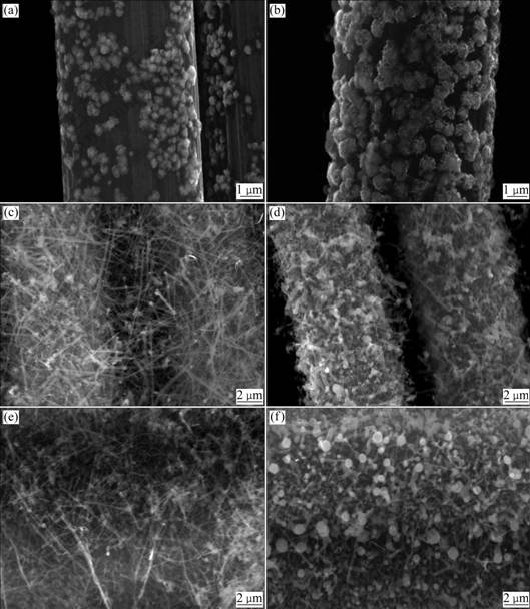
Fig.1 SEM images of carbon fibers after electroplating with Ni and coating with SiC-NFs by CCVD: (a) Electroplating with Ni for 5 min; (b) Electroplating with Ni for 10 min; (c) Electroplating for 5 min and CCVD for 2 h; (d) Electroplating for 10 min and CCVD for 2 h; (e) Electroplating for 5 min and CCVD for 6 h; (f) Electroplating for 10 min and CCVD for 6 h
Fig.2 shows the TEM morphologies of the SiC-NFs and selected diffraction on the sample surface. As shown in Fig.3(a), the SiC-NFs are straight and Ni catalyst nanogranules are found (shown by the arrow in Fig.2(c)).
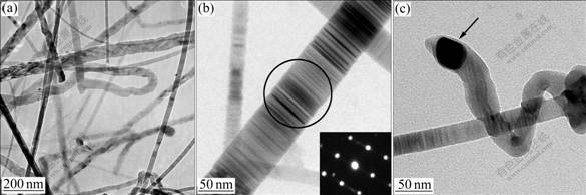
Fig.2 TEM images of SiC-NFs grown from Ni catalyst (plating for 5 min and CCVD for 4 h): (a) Morphology of SiC-NFs; (b) Selected diffraction pattern on surface of SiC-NFs; (c) Individual SiC-NF with Ni particle
Fig.3 shows the XRD patterns of carbon felts after coating with SiC by CCVD for 2 h with plating Ni for 10 min. The diffraction peaks of C, ��-SiC and Ni are observed. The mass fraction of ��-SiC is found to reach 10% as determined by phase analysis of XRD.
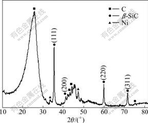
Fig.3 XRD pattern of carbon felts produced after electroplating with Ni for 10 min and then coating with SiC
3.1 Preparation of SiC-NF/carbon fiber composite felts
As shown in Fig.1(a), the Ni-nanogranules produced have diameters of several nanometers. But the Ni granules in Fig.1(b) are larger than those in Fig.1(a) and have diameters in the range of hundreds of nanometers; and the whole surface of the CFs is almost covered with Ni granules. In this respect, by keeping the current at 100 mA, the size, morphology and the amount of plating Ni on the surface of the CFs would be controlled by adjusting the plating time. As shown in Figs.1(c) and (d), after plating the surface of the CFs with Ni, the nanofibers are deposited in situ on the surface of the CFs. When plating with Ni for 5 min, the resulting Ni nanogranules are small and thin. As such, the corresponding nanofibers produced by CCVD are more spindle-like. When plating with Ni for 10 min, the resulting nanofibers are observed to increase in diameter. These results prove that the size of the catalyzer is directly related to the morphology and quantity of the nanofibers produced. As shown in Figs.1(e) and (f), the longer the CCVD time is, the more the nanofibers are deposited on the CF surface. The carbon fibers in Figs.1(c) and (d) are barely bridged by CCVD fibers, so the carbon fiber matrix is easily distinguished after CCVD. However, in Figs.1(e) and (f), the carbon fibers are notably bridged by CCVD fibers, making it difficult to distinguish the carbon fiber substrate. These bridged carbon fibers make each of them not a single fiber as reinforcement phase in composite materials; and they will play a key role in producing highly strong nanofibers by CCVD. In addition, the traditional carbon felts, whether planar, two-dimensional or three- dimensional, invariably cause anisotropy after compositing. As described above, the effect of bridging and growing of random nanofiber composite felts will improve this anisotropy. Moreover, it is also expected to improve the properties of the fiber-reinforced composites such as strength, modulus, corrosion and oxidation resistance, electric and heat conduction.
3.2 Phase constitution of SiC-NF/CF composites
As shown in Fig.3, the observed phases of the composite felts after CCVD include C, ��-SiC and Ni. The C diffraction peak is broad, which indicates that the carbon felts contain polycrystalline graphite. The ��-SiC diffraction peak is sharp corresponding to the JCPDS CARD No.29-1129[14]. From above, the ��-SiC nanofibers are grown on the CF surface in situ in the carbon felts after plating with Ni and then coating with SiC by CCVD. Fig.2(b) shows that the as-produced SiC-NFs are composed of single crystal. The ��-SiC fibers behave as reinforcements for the composite material, resulting in properties of high specific strength, high specific modulus, high-temperature stability and high corrosion and resistance durability. Moreover, the ��-SiC nanofibers can improve the compatibility between the carbon fibers and the matrix material (pitch, resin or metal)[15]. Thereby, the ��-SiC nanofibers improve the properties of the resulting composite material prepared with C/C or C/SiC composites.
3.3 Effect of plating and CCVD time on growth velocity and morphology of SiC-NFs
The mass gain of the as-received samples and the different-time electroplated samples are converted into mass increase percent. Fig.4 is obtained by considering the relationship between CCVD time and mass increase percent. As shown in Fig.5, the mass increase rate is calculated on the basis of data obtained at different CCVD time. In Fig.5, compared with the non-electroplated samples, electroplating with Ni can improve the deposition velocity of SiC by CCVD at the same plating time. The longer the electroplating time is, the more the SiC-NFs are produced by CCVD. But if the electroplating time surpasses 5 min, the corresponding mass increase is negligible. Moreover, by keeping the same electroplating time, and prolonging the CCVD time, more SiC-NFs are observed on the CF surface and the mass increases accordingly. But over different periods of time, the increased velocity is observed to change. As shown in Fig.5, after the initial period of seeding nanocrystals, the nanofibers grow rapidly. Here, the catalytic reaction is active during the first 4 h, and the growth velocity reaches the maximum at 4 h. Then, the activity lessens and the growth velocity becomes slow and nearly constant at around 8 h. Besides, the growth velocity of the electroplated samples is still higher than that of conventional non-electroplated samples. After 8 h, the catalytic activity of Ni is low, and the nanofiber growth is slow. However, the CF surface is coated with several nanofibers during the first period of the reaction, and this improves the specific surface area and the activity of the surface. SiC coated by CVD occurs on the surface of carbon fibers and SiC-NFs at the same time, so the velocity is faster than the conventional sample without a catalyzer. For those samples with different electroplating time, after CVD for 8 h, the more the catalyzer there is on the surface and the more the SiC-NFs there are, the faster the growth velocity becomes stable once the catalyzer loses activity. Therefore, for carbon felts electroplated with Ni and coated with SiC by CCVD, the growth velocity in chemical vapor infiltration(CVI) C/C and C/SiC composite materials is found to increase.
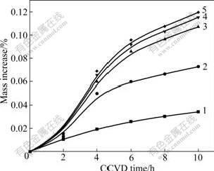
Fig.4 Relationship between CCVD time and mass increase percent of different samples: 1 As-received; 2 Electroplated with Ni for 2.5 min; 3 Electroplated with Ni for 5 min; 4 Electroplated with Ni for 7.5 min; 5 Electroplated Ni with for 10 min

Fig.5 Relationship between CCVD time and mass increase rate of different samples: 1 As-received; 2 Electroplated with Ni for 2.5 min; 3 Electroplated with Ni for 5 min; 4 Electroplated with Ni for 7.5 min; 5 Electroplated with Ni for 10 min
4 Conclusions
1) After electroplating a Ni catalyzer on the CF surface, the SiC-NF/CF composite felts are prepared in situ by the methods of CCVD. XRD and TEM results show that the CCVD SiC-NFs are composed of single crystal of ��-SiC.
2) The size, morphology and distribution of Ni granules have a great effect on the CCVD of SiC-NFs. Smaller and well-distributed Ni granules result in more spindle-like SiC-NFs with an even distribution. Longer electroplating time results in more Ni nanogranules grown on the surface of the CFs, and a faster growth of CCVD SiC-NFs.
3) The growth velocity of the SiC-NFs is found to reach the maximum at around 4 h, and becomes nearly constant at around 8 h due to the Ni catalyzer experiencing a loss of activity. After 8 h, the stable growth velocity of the electroplated Ni samples is faster than that of conventional samples without a catalyzer due to an improvement in the surface activity resulting from CCVD SiC-NF.
References
[1] WUNDERLICH W. Growth model for plasma-CVD growth of carbon nano-tubes on Ni-sheets [J]. Diamond and Related Materials, 2007, 16(2): 369-378.
[2] HU M H, MURAKAMI Y, OGURA M, MARUYAMA S, OKUBO T. Morphology and chemical state of Co-Mo catalysts for growth of single-walled carbon nanotubes vertically aligned on quartz substrates [J]. Journal of Catalysis, 2004, 225(1): 230-239.
[3] SONG Yue-qin, HE De-hua, XU Bo-qing. Effects of preparation methods of ZrO2 support on catalytic performances of Ni/ZrO2 catalysts in methane partial oxidation to syngas [J]. Applied Catalysis A: General, 2008, 337(1): 19-28.
[4] CHIANG W H, SANKARAN R M. Microplasma synthesis of metal nanoparticles for gas-phase studies of catalyzed carbon nanotube growth [J]. Applied Physics Letters, 2007, 91(12): 1-3.
[5] SIMAS R, VALENTINAS S. Method for the simple catalytic carbon nano-fibers growth in air [J]. Microelectronic Engineering, 2006, 83: 1538-1541.
[6] UCHIDA T, ANDERSON D P, MINUS M L, KUMAR S. Morphology and modulus of vapor grown carbon nano fibers [J]. Journal of Materials Science, 2006, 41(18): 5851-5856.
[7] YOON S H, LIM S, HONG S H, QIAO W M, WHITEHURST D, ISAO D M, ANB B, KIYOSHI Y. A conceptual model for the structure of catalytically grown carbon nano-fibers [J]. Carbon, 2005, 43(9): 1828-1238.
[8] LIJIE C, JINQUAN W. Carbon nanofibers and sigle-walled carbon nanotubes prepared by the floating catalyst method [J]. Carbon, 2001, 39: 329-335.
[9] MORANCAISA A, CAUSSATB B, KIHNC Y, KALCKA P, PLEED D, GAILLARDD P, BEMARDE D, SERPA P. A parametric study of the large scale production of multi-walled carbon nanotubes by fluidized bed catalytic chemical vapor deposition [J]. Carbon, 2007, 45(3): 624-635.
[10] WANG X, HU Z, CHEN X, CHEN Y. Preparation of carbon nanotubes and nano-particles by microwave plasma-enhanced chemical vapor deposition [J]. Scripta Materialia, 2001, 44(8/9): 1567-1570.
[11] MATSUMOTO Y, MYO THAN OO, NAKAO M, KAMINMURA K, ONUMA Y, MATSUSHIMA H. Preparation of carbon nanofibers by hot filament-assisted sputtering [J]. Mater Sci Eng B, 2000, 74(1/3): 218-221.
[12] XU Xian-feng, XIAO Peng, XU Lin, XIONG Xiang, HUANG Bai-yun. Preparation of carbon felts reinforced by both SiC nano-fibers and carbon fibers [J]. Journal of Functional Materials, 2008, 39(4): 692-694.
[13] KRNEL K, STADLER Z, KOSMAC T. Preparation and properties of C/C-SiC nano-composites [J]. Journal of the European Ceramic Society, 2007, 27(2/3): 1211-1216.
[14] JCPDS, International Center for Diffraction Data. Powder diffraction file, Card No.29-1129 [S]. Swarthmore, Pennyslvania, USA..
[15] ZHU Yao-can, OHTANI S, SATO Y, IWAMOTO N. The improvement in oxidation resistance of CVD-SiC coated C/C composites by silicon infiltration pretreatment [J]. Carbon, 1998, 36: 929-935.
Foundation item: Project(2006CB600904) supported by the National Basic Research Program of China
Corresponding author: XU Xian-feng; Tel: +86-13647095289; E-mail: xu-xianfeng@163.com
DOI: 10.1016/S1003-6326(08)60420-3
