

Experimental investigation of laser surface processing of flexure silicon nitride ceramic
SUN Li1, A. P. MALSHE1, JIANG Wen-ping1, P. H. MCCLUSKEY2
1. Department of Mechanical Engineering, University of Arkansas, Fayetteville, AR 72701, USA;
2. Technology & Solutions Division, Caterpillar Inc., Peoria, IL 61629, USA
Received 10 April 2006; accepted 25 April 2006
Abstract:
A continuous wave carbon dioxide (CO2) laser (��=10.6 ��m) was employed to treat the surface of Si3N4 MOR (modulus of rupture) bars. The effects of the CO2 laser process on physical and mechanical properties of ground Si3N4 samples were investigated. Scanning electron microscopy (SEM) analysis shows that the area occupied by cavities and fracture is decreased by about 49.4% after laser treatments. Cross-sectional metallography results indicate that the secondary YSiAlON phase in the Si3N4 ceramic is softened/melted and flowed into the defects. Four-point bending tests show that the flexural strength of the treated samples is improved to 10.9%. Fractographic analysis show that the fracture origins move from the surface to subsurface. It is concluded that laser surface processing have significant effects on fracture behavior of flexure Si3N4 ceramic.
Key words:
Si3N4; silicon nitride ceramic; laser surface processing; surface integrity; flexural strength; fracture origin;
1 Introduction
Silicon nitride(Si3N4) ceramic has been used in various engineering applications such as bearings, valves, rotors, and rollers because of its low density, high-temperature strength, excellent corrosion, wear, and thermal shock resistance[1-3]. However, the properties that make Si3N4 useful are coupled with limited ductility, which makes the material very difficult to machine[4]. Diamond grinding is the most widely accepted method to produce precision Si3N4 parts in industry. The machining process involves material removal by means of deformation and brittle fracture[5, 6]. Due to heat generation, impact and sliding of the diamond abrasives, surface and subsurface defects, such as micro-cavities, micro-cracks, smeared areas and debris, are generated[7, 8].
Extensive efforts have been taken to evaluate the effect of grinding process on the flexural strength of Si3N4 ceramic [9-16]. Machining effects were discussed by examining the Weibull distribution curves and strength data. Degradation in strength of the ceramic was observed after grinding process [9-14]. RICE et al. [15] investigated the flaws from which failure initiated. They reported the difference in the two sets of machining flaws, orthogonal and parallel to the grinding direction, was a major factor in the effect of grinding direction on strength. QUINN et al [16] applied fractographic analysis to characterize the size, shape, and severity of grinding defects in Si3N4 ceramic, and established the correlation between grinding-induced flaws and grinding conditions. Research has been conducted to reduce the surface and subsurface machining defects. Traditional methods include furnace annealing, lapping/polishing, and oxidation of the surface. However, decrease of flexural strength of the processed samples was reported [16-18].
In this paper, CO2 laser surface processing was proposed to reduce or eliminate the grinding-induced defects. Unlike laser machining [19-21] and laser-assisted machining [22-24], CO2 laser surface processing was applied as a post-grinding process in the present research. After coarse grinding, Si3N4 samples were treated by a CO2 laser to remove the machining-induce defects. The surface integrity (henceforth, this refers to cavities and fracture areas), flexural strength, and fracture origins of the Si3N4 samples after the laser surface processing were systematically investigated. Correlations of character-
istics of fracture origins with laser surface processing parameters were presented.
2 Experimental
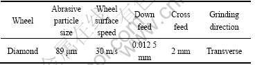
The silicon nitride ceramic (ceralloy? 147-31N) used in this research work was sintered reaction bonded silicon nitride (SRBSN) from Ceradyne Inc. This SRBSN had needle-like beta silicon nitride grains bonded by YSiAlON glassy phase as shown in Fig.1. The grinding operation was performed by Chand Associates Inc. in accordance with the ASTM standard (C1161-02C) to produce 50 mm��4 mm��3 mm MOR (Modulus of Rupture) bars. The top surface (50 mm��4 mm) of the samples was coarsely ground and used as the testing surface. The specific coarse grinding conditions are listed in Table 1. It is known that the grinding direction has great influence on the flexural strength of silicon nitride samples. Compared to samples ground in longitudinal direction, samples ground in transverse direction are more significantly degraded in strength [11]. Therefore, the test surface in this research was intentionally ground in transverse direction to study the effect of CO2 laser surface processing. The cracks generated with grinding conditions specified in Table 1 were around 30-70 ��m deep [16].
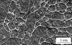
Fig.1 Microstructure of Si3N4 ceramic used in this study
Table 1 Coarse grinding conditions for test surface of Si3N4 bars
Two continuous wave (CW) carbon dioxide (CO2) lasers were applied for surface treatment. An 80 W CO2 laser (L80A, Laser Machining Inc.) was used for low power density treatments, a 1.5 kW CO2 laser (Model 820, Rofin-Sinar?) for intermediate and high power density treatments. A 25.4 mm diameter plano-convex cylindrical lens (effective focal length 127 mm) was used to convert the circular beam into a10 mm��0.4 mm rectangular beam, which was suitable for scanning the samples. Fig.2 shows the experimental
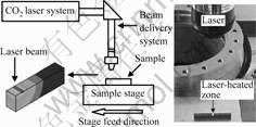
Fig.2 Experimental setup for CO2 laser surface processing of Si3N4 samples
setup used in this study.
In laser processing, the Si3N4 surface temperature will be increased. Typically, the YSiAlON glassy phase in Si3N4 is known to be stable up to 920-970 �� [25]; Si3N4 starts decomposition at around 1 877 �� [21]. In this research, the goal was to re-flow the glassy phase while retaining the primary Si3N4 phase. Therefore, the required surface temperature must be higher than the stable temperature of the YSiAlON glassy phase, and lower than the decomposition temperature of the primary Si3N4 phase. To estimate this temperature window, a FEA (finite element analysis) model was constructed to simulate the laser surface processing and to determine the corresponding processing parameters. In this model, a Si3N4 MOR bar and a sample supporter (a Si3N4 ceramic plate) were built. Physical and thermal properties of Si3N4 ceramic were obtained from the manufacturer. The initial temperature of the sample and the sample supporter was room temperature (22 ��). Based on the theoretical calculation, energy loss through convection and radiation on the sample and sample supporter was about 3% of the energy input by the laser. Therefore, convection and radiation were ignored and surfaces exposed in the air ambient were treated to be insulated in the model. The temperature of the bottom surface (150 ��) of the sample supporter was set based on the temperature measurement using a PM180 inframetrics infrared thermal camera (emissivity coefficient 0.95, corrected according to the manual of the infrared thermal camera). Since laser power density and scanning speed determine the temperature for the given beam dimension and material, they were selected as the main input parameters. Surface integrity and flexural strength, which are affected by the surface defects, were selected as the main output parameters for process optimization. The laser treatment parameters determined using FEA simulation are listed in Table 2. According to the simulation results, the highest temperature at sample surface was mainly determined by laser power density. As the laser power density was 30 MW/m2, the highest temperature at sample surface was around 950 ��. The highest surface temperature was around 1 250 �� at power density 50 MW/m2 and around 1 550 �� at power density 70 MW/m2. The depth of heat penetration was around 200 ��m where the temperature in the sample was around or higher than the stable temperature of the glassy phase based on the simulation results.
Table 2 CO2 laser parameters for surface processing of Si3N4 samples

Prior to laser treatments, all the samples were cleaned by using an ultrasonic cleaner with ethanol. The laser treatment was carried out at ambient environment. Each sample was treated with one scanning pass and then was cooled to room temperature in air. Various analytical techniques including scanning electron microscopy (SEM), four-point bending test, fractographic analysis and X-Ray diffraction (XRD) were employed to study the effect of CO2 laser process parameters on the fracture behavior of flexure Si3N4 samples after the surface processing.
To attain the cross-sectional metallograph, the Si3N4 samples were sectioned with a diamond cutting wheel and then well polished according to the standard polishing procedure provided by Buehler Inc. The polished sections were then plasma etched to obtain the microstructure as shown in Fig.1. The plasma etching process was performed at 100 W in 96%(volume fraction) CF4 and 4% O2 with a gas pressure of 30 Pa. The plasma etching was carried out for 10 min.
3 Results and discussion
3.1 Surface integrity
Surface integrity plays an important role in the flexural strength and fracture behavior of Si3N4 ceramic due to its sensitivity to surface damage. A scanning electron microscope (Hitachi model S-2300) was employed to study the surface conditions after laser processing. Fig.3 shows the surface morphology of the Si3N4 samples before and after laser processing with different treatment conditions. To evaluate the surface integrity, the total area of cavities and fracture areas in an area of 4 000 ��m2 on the surface of three samples for each treatment condition was calculated. As shown in Fig.4 the area of cavities and fracture areas was reduced, inferring the surface integrity was improved after laser treatments.
A significant improvement of material surface integrity with increased laser power density was demonstrated in Fig.4 (at the same laser scanning speed). When the laser power density was 30 MW/m2, particularly for faster scanning speed the treated material surface was not affected significantly compared to the untreated surface. However, as laser power density reached 50 MW/m2, SEM as well as calculated cavities and fracture areas showed major surface modifications. At the laser density higher than 50 MW/m2, the processed samples did not show significant improvement in surface integrity compared to samples processed at 50 MW/m2. This indicates that the improvement of surface integrity may have reached saturation with increasing laser power density. The laser scanning speed had significant effects on the improvement of surface integrity when comparing treated samples to untreated samples as shown in Fig.4.
It is believed that the improvement of the surface integrity is attributed to the re-flowing and rebinding process of the secondary YSiAlON glassy phase. During the CO2 laser processing, the temperature at the surface of Si3N4 samples was higher than the stable temperature of the secondary phase. The secondary phase was softened or even melted, and flowed into the surface defect sites. As a result, the surface integrity was improved. The higher the laser energy density, the better the flow and rebinding ability of the secondary phase. As a result, better surface integrity was attained. The cross-sectional metallographs shown in Fig.5 illustrate representative microstructures just underneath the sample surface before and after the laser processing. It can be seen that before the laser processing, defects such as voids in the secondary phase (at triple Si3N4 grain junction) and discontinuous secondary phase (at two Si3N4 grain junction) were present in the sample. After the laser processing, the defects were removed and the secondary phase was continuous. The observation of the removal of the defects confirmed the re-flowing and rebinding process of the secondary glassy phase.
3.2 Flexural strength
A universal testing machine with a fully articulating four-point fixture (Tinius Olsen Testing Machine Co., Inc.) was used to test the flexural strength of untreated and treated samples. Thirty samples were tested for each group as per the ASTM standard C1161-02C. For reference, the flexural strength of the SRBSN is 700-800 MPa (provided by the manufacturer).
Fig.6 plots the average flexural strength of untreated and treated samples at different processing conditions. The light lines connecting data points in Fig.6 are only
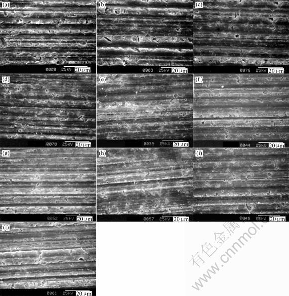
Fig. 3 Surface morphologies of Si3N4 samples before and after laser treatments: (a) Untreated samples; (b) 30 MW/m2, 1.0 mm/s; (c) 30 MW/m2, 0.5 mm/s; (d) 30 MW/m2, 0.1 mm/s; (e) 50 MW/m2, 1.0 mm/s; (f) 50 MW/m2, 0.5 mm/s; (g) 50 MW/m2, 0.1 mm/s; (h) 70 MW/m2, 1.0 mm/s; (i) 30 MW/m2, 0.5 mm/s; (j) 70 MW/m2, 0.1 mm/s
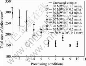
Fig. 4 Total area of cavities and fracture areas in area of 4 000 ��m2 on surface of samples before and after laser treatments
samples. With increasing laser power density and processing time (decreased scanning speed), the flexural strength of treated samples increases. Meanwhile, a significant increase of the Weibull modulus was obtained, suggesting that the distribution of the flaws in the samples was affected after laser processing (see detailed discussion in the following section). It is evident a saturation state of the improvement of flexural strength and Weibull modulus was reached as the power density was increased from 50 to 70 MW/m2. At the process condition of 70 MW/m2 and 0.5 mm/s, the largest flexural strength and Weibull modulus of treated samples were achieved with a 10.9% increased of characteristic strength compared to that of untreated samples.
Fig.7 shows the failure data of the four-bending tests. There are two distinct groups in this plot. The first groups is formed by the untreated samples and samples treated at condition of 30 MW/m2-1.0 mm/s and
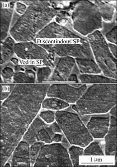
Fig. 5 Cross-sectional metallographs of Si3N4 samples: (a) Untreated sample (SP: secondary phase); (b) Laser treated at 70 MW/m2, 0.5 mm/s
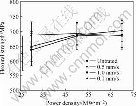
Fig. 6 Average flexural strength of Si3N4 samples before and after CO2 laser treatments
30 MW/m2-0.5 mm/s. The second group is formed by the samples treated at all other processing conditions. The formation of the two groups of samples was related to the surface integrity after the laser processing. As the laser power density was 30 MW/m2, improvement of surface integrity was limited particularly for faster scanning speed. Samples had a higher probability to fail from the machining-induced defects on the sample surface with low applied loads, leading to a low flexural strength of the samples. With higher energy input, decrease of defects on the sample surface was significant. As a result, the samples had a lower probability to fail
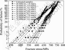
Fig.7 Weibull strength distribution plots of Si3N4 samples before and after CO2 laser treatments
from the flaws at the surface, and the flexural strength was increased. Furthermore, the saturation state of the flexural strength improvement from 50 MW/m2 to 70 MW/m2 was correlated (correlation coefficient=0.933) to the saturation of the surface integrity improvement from 50 MW/m2 to 70 MW/m2, suggesting that flexural strength was closely related to surface integrity.
3.3 Fractographic analysis
To identify the fracture origins, the fractographic analysis was performed in accordance with the ASTM standard C1322-02a. All fracture surfaces were examined with a stereo binocular microscope to locate the fracture origin and the fracture mirror. Ten samples of each group were selected for further characterization with the SEM. For untreated samples, it was found that the there were two types of fracture origins: machining induced cracks and material inherent flaws such as agglomerates and pores/ porous regions. Machining induced cracks were surface located with a depth around 25-50 ��m. The material inherent flaws can be surface located or near-surface located. The scatter of the fracture origins led to the relatively low Weibull modulus of untreated samples. Fig.8 shows the fracture origin in an untreated sample. In this case, the fracture origin was a 30 ��m deep ��zipper machining crack��, which had zigzag kinks and was caused by transverse grinding process. Fig.9 illustrates an example that the fracture origin of an untreated sample was a surface located material inherent flaw (agglomerates).
With a low laser power density (30 MW/m2) and relatively fast scanning speeds (0.5 and 1.0 mm/s), the improvement of surface integrity was limited. The observed type and location of fracture origins of treated samples were not significantly different from that of untreated samples. At the process condition of 30 MW/m2-0.1 mm/s, the healing effect on grinding-
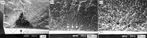
Fig. 8 SEM images illustrating fracture surface of untreated sample (608 MPa): (a) Fracture surface; (b) Fracture mirror; (c) Fracture origin
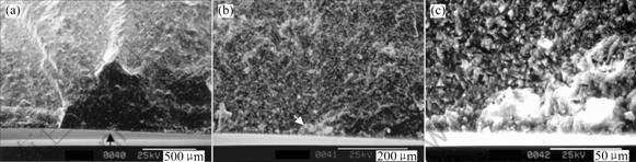
Fig. 9 SEM images showing fracture surface of untreated sample (583 MPa): (a) Fracture surface; (b) Fracture mirror; (c) Fracture origin
induced defects emerged due to the relatively long processing time. The cracks became blunt and shallow (around 15-35 ��m in depth) because of re-flowing and rebinding of the secondary glassy phase. As a result, the regions where machining cracks connected with material inherent flaws were more vulnerable than the blunt cracks. Therefore, the fracture origin changed to surface/near-surface connections of material inherent flaws with blunt machining defects. It is found that around 80% of the treated samples (30 MW/m2-0.1 mm/s) fails from this type of fracture origins and the rest samples failed from the machining induced cracks or material inherent flaws. The fracture origin shown in Fig.10 exhibits interaction between 25 ��m deep laser-treated machining cracks and near-surface located material inherent flaws (pores/porous regions).
When the laser power density reached 50 and 70 MW/m2, two main types of fracture origins were identified based on the applied laser scanning speed. With relatively low scanning speeds (0.5 and 0.1 mm/s), the machining defects were significantly reduced, and weak regions on the surface were strengthened. Therefore, fracture initiated from the material inherent flaws with higher probability than from laser-treated surface defects. Meanwhile, near-surface located material inherent flaws such as pores and porous regions were partially removed after the laser processing. The total effect was to change fracture origins to near-surface located or volume located material inherent flaws after the laser processing. More than 70% of the treated samples (50 and 70 MW/m2, 0.5 and 0.1 mm/s) fail from this type of fracture origins, locat up to around 60 ��m below the surface. The fracture origin shown in Fig.11 is a representative illustration, where the origin is a volume located pore/porous region (50 ��m below the surface) in a sample treated with a process condition of 70 MW/m2-0.5 mm/s. With a high scanning speed (1.0 mm/s), the process time was relatively short, and therefore the surface and subsurface defects removed were not as many as defects removed in the cases where lower scanning speeds were applied. As a result, approximately 70% of the treated samples failed from the surface/near-surface connections of material inherent flaws with blunt machining defects, same type of the fracture origin as samples treated with 30 MW/m2-0.1 mm/s; the fracture origins of the rest samples were identified as near-surface or volume located material inherent flaws and machining induced cracks. In the samples treated with high laser power densities (50 and 70 MW/m2), the distribution of fracture origins was more confined than that of untreated samples. The observation consisted with the higher Weibull modulus associated with samples treated with high laser power densities.
As discussed above, it is evident that the fracture origins are closely correlated to the laser surface processing conditions as shown in Fig.12. With the effect of the laser power density and scanning speed, fracture origins changed from machining-induced defects,
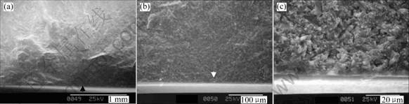
Fig.10 SEM images illustrating fracture surface of sample treated at 30 MW/m2-0.1 mm/s (670 MPa): (a) Fracture surface; (b) Fracture mirror; (c) Fracture origin
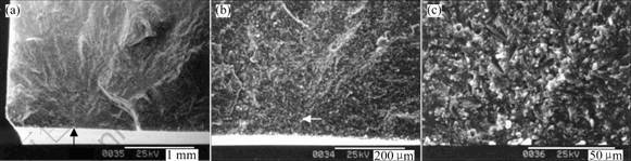
Fig.11 SEM images showing fracture surface of sample treated at 70 MW/m2-0.5 mm/s (721 MPa): (a) Fracture surface; (b) Fracture mirror; (c) Fracture origin
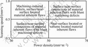
Fig.12 Correlation between fracture origins and laser processing conditions
surface/near-surface located material inherent flaws to surface/near-surface connections of material inherent flaws with blunt machining defects, and finally, to near-surface located or volume located material inherent flaws. The general trend, fracture origins moving towards the bulk material, was caused by the improvement of the surface and subsurface integrity of the ceramic after the laser processing. As a result, the flexural strength and Weibull modulus were improved.
4 Conclusions
The effects of CO2 laser surface processing on the fracture behavior of flexure silicon nitride ceramic were systematically investigated. It is found that the laser power density and laser scanning speed have significant effects on the improvement of surface integrity and flexural strength of Si3N4 samples. The flexural strength of laser-treated samples is increased to 10.9% compared to that of the untreated samples. The fracture behavior of the flexure samples is closely correlated to the laser surface processing conditions. The fracture origins are found to change from machining-induced defects, surface/near-surface located material inherent flaws to surface/near-surface connections of material inherent flaws with blunt machining defects, and finally, to near-surface located or volume located material inherent flaws, due to the improvement of surface and subsurface integrity induced by laser treatments.
Acknowledgments The authors gratefully acknowledge the financial support for this research from the National Science Foundation (DMI-0085233), Dr. Palaniappa A. Molian (Iowa State University) for providing high power laser facilities, and Dr. Said Jahanmir (MiTiHeart Corporation) for technical discussions.References[1] CHINNAKARUPPAN P, MALSHE A P, YEDAVE S N, PARK B S, SCHIMDT W F, GORDON M H, BATZER S A, BROWN W D. Laser-assisted surface engineering of silicon nitride to minimize the surface defects generated during grinding operation��part I[A]. Proceedings of the ASME[C]. Manufacturing in Engineering Division, 2000, 11: 959-966.
[2] SUN L, SHAW L L, MARCUS H L. Silicon nitride coatings formed using the selective area laser deposition (sald) technique[J]. Materials Research Society Symposium-Proceedings, 1999, 555: 179-184.
[3] SOLOMAH A G. Laser Machining of Silicon Nitride Ceramics[M]. NIST Special Publication, 1993.
[4] MEINERS E, WIEDMAIER M, DAUSINGER F, KRASTEL K, MASEK I, KESSLER A. Micro machining of ceramics by pulsed Nd: YAG laser[J]. LIA (Laser Institute of America), 1992, 74: 327-336.
[5] JAHANMIR S, STRAKNA T J, QUINN G D, LIANG H, ALLOR R L, WEST R D. Effect of Grinding on Strength and Surface Integrity of Silicon Nitride: Part I[M]. NIST Special Publication, 1993.
[6] ZHANG G M, ANAND D K., GHOSH S, KO W F. Study of the Formation of Macro- and Micro-Cracks During Machining of Ceramics[M]. NIST Special Publication, 1993.
[7] XU H H K, JAHANMIR S, IVES L K. Material removal and damage formation mechanisms in grinding silicon nitride[J]. Journal of Material Research, 1996, 11: 1717-1724.
[8] OTT R D, BREDER K, WATKINS T R, FERBER M K, RIGSBEE J M. Characterization of machining-induced sub-surface damage of a high strength silicon nitride[J]. Ceramic Engineering and Science Proceedings, 1997, 18: 93-103.
[9] KIM B A, ANDO K, SATO S. Effect of grinding on cracks and the strength of ceramics[J]. Fatigue and Fracture of Engineering Materials & Structures, 1994, 17: 187-200.
[10] MAYER J E Jr, FANG G P. Effect of grit depth of cut on strength of ground ceramics[J]. CIRP Annals, 1994, 43: 309-312.
[11] STRAKNA T J, JAHANMIR S, ALLOR R. L, KUMAR K V. Influence of grinding direction on fracture strength of silicon nitride[J]. Journal of Engineering Materials and Technology, Transactions of the ASME, 1996, 118: 335-342.
[12] BREDER K, WERESZCZAK A A, ANDREWS M J. Exploration of the Weibull modulus as a function of surface preparation and flexure testing conditions[J]. Ceramic Engineering and Science Proceedings, 1998, 19: 89.
[13] LI K, LIAO T W. Surface/subsurface damage and the fracture strength of ground ceramics[J]. Journal of Materials Processing Technology, 1996, 57: 207.
[14] WOBKER H G, TONSHOFF H K. High Efficiency Grinding of Structural Ceramics[M]. NIST Special Publication, 1993.
[15] RICE R W, MECHOLSKY J J Jr, BECHER P F. The effect of grinding direction on flaw character and strength of single crystal and polycrystalline ceramics[J]. Journal of Materials Science, 1981, 16: 853.
[16] QUINN G D, IVES L K, JAHANMIR S. On the Fractographic Analysis of Machining Cracks in Ground Ceramics: A Case Study on Silicon Nitride[M]. NIST Special Publication, 2003.
[17] TOMLINSON W J, NEWTON R C. Effect of grinding, lapping and various surface treatments on the strength of silicon nitride[J]. Ceramics International, 1990, 16(5): 253-257.
[18] PARK H, KIM H W, KIM H E. Oxidation and strength retention of monolithic Si3N4 and nanocomposite Si3N4-SiC with Yb2O3 as a sintering aid[J]. Journal of the American Ceramic Society, 1998, 81(8): 2130-2134.
[19] STEEN W M. Laser Material Processing[M]. New York: Springer Verlag, 1996.
[20] ISLAM M U, CAMPBELL G. Laser machining of ceramics: a review[J]. Materials and Manufacturing Processes, 1993, 8: 611-630.
[21] MORITA N, WATANABE T, YOSHIDA Y. Crack-free processing of hot-pressed silicon nitride ceramics using pulsed YAG laser[J]. JSME International Journal, 1991, 34: 149-153.
[22] ROZZI J C, PFEFFERKORN F E, INCROPERA F P, SHIN Y C. Experimental evaluation of the laser assisted machining of silicon nitride ceramics[A]. Proceedings of ASME MSE Division[C]. 1998: 229-239.
[23] LEI S, SHIN Y C, INCROPERA F P. Experimental investigation of thermo-mechanical characteristics in laser-assisted machining of silicon nitride ceramics american society of mechanical engineers[J]. Manufacturing Engineering Division, MED, 1999, 10: 781-788.
[24] REBRO P A, PFEFFERKORN F E, SHIN Y C, INCROPERA F P. Comparative assessment of laser-assisted machining for various ceramics[A]. Technical Paper��Society of Manufacturing Engineers[C]. 2002, MR02-198, 1-8.
[25] HAMPSHIRE S R., DREW A L, NAJACK K H. Viscosities, glass transition temperature, and microhardness of Y-Si-Al-O-N glasses[J]. Journal of American Ceramic Society, 1984, 76: C46-C47.
(Edited by YANG Hua)
Foundation item: Project(DMI-0085233) supported by the National Science Foundation of USA
Corresponding author: A. P. MALSHE; Tel +1-479-575-6561; Fax: +1-479-575-6982; E-mail: apm2@engr.uark.edu
