
J. Cent. South Univ. (2012) 19: 1447-1453
DOI: 10.1007/s11771-012-1161-8![]()
Beam-track interaction of high-speed railway bridge with ballast track
YAN Bin(�Ʊ�)1, DAI Gong-lian(������)1, ZHANG Hua-ping(�Ż�ƽ)2
1. Department of Civil Engineering, Central South University, Changsha 410075, China;
2. Maintenance Departments of Guangzhou Municipal Engineering, Guangzhou 510100, China
? Central South University Press and Springer-Verlag Berlin Heidelberg 2012
Abstract:
Based on the construction bridge of Xiamen-Shenzhen high-speed railway (9-32 m simply-supported beam + 6��32 m continuous beam), the pier-beam-track finite element model, where the continuous beam of the ballast track and simply-supported beam are combined with each other, was established. The laws of the track stress, the pier longitudinal stress and the beam-track relative displacement were analyzed. The results show that reducing the longitudinal resistance can effectively reduce the track stress and the pier stress of the continuous beam, and increase the beam-track relative displacement. Increasing the rigid pier stiffness of continuous beam can reduce the track braking stress, increase the pier longitudinal stress and reduce the beam-track relative displacement. Increasing the rigid pier stiffness of simply-supported beam can reduce the track braking stress, the rigid pier longitudinal stress and the beam-track relative displacement.
Key words:
high-speed railway; beam-track interaction; ballast track; rail longitudinal force; continuous beam��
1 Introduction
In recent years, the remarkable achievements were made in high-speed railway in China. On one hand, train speed has been increased (In December 2010, ��Harmony�� CRH380 high-speed train reached 486.1 km/h maximum speed of the world��s operating railway tests). On the other hand, by the end of 2010, the operating mileage of China��s high-speed railway reached 8 358 km, which is the longest in the world. In order to cross the valley, rivers and existing lines, and in order to control the foundation settlement in the areas of poor geological conditions, the bridge was widely used in high-speed railway [1]. The seamless and welded long rail line of the high-speed railway was commonly used in China. As the role of longitudinal resistance on track bed, the beam-track relative displacement is bound, and the mechanical balance system of mutual restraint is formed by both beam and track. In order to ensure the safety and comfort of trains, the longitudinal force caused by the beam-track interaction must be thought over in continuously welded rail (CWR) high-speed railway bridges.
In 1985, the ��Special Procedures on Shinkansen Railway Bridge (DS899/59)�� [2] promulgated by Federal Republic of Germany showed that Germany has studied the longitudinal force for many years. In 2001, tension and compression connectors were studied through calculating and test by YIN et al [3]. In 2005, the static and dynamic 3D finite element model of the beam-track vertical interaction was established by XU [4]. In 2006, some features on the unequal span combination of concrete simply-supported beam and steel truss bridge were analyzed and compared with equal span simply-supported beam and steel truss bridge by LI [5]. In 2008, the beam-track interaction model considering the impact on follow-up structure was used to derive the computing method of longitudinal stiffness in follow-up structure by JIANG [6].
Though extensive research on the beam-track interaction for bridge CWR was made so as to form more mature norm to guide the design of bridge CWR, some regulations for simply-supported beams were generally conducted by the norm, while fewer regulations for continuous beams [2, 7]. Taking the construction bridge of Xiamen-Shenzhen high-speed railway (9-32 m simply-supported beam + 6��32 m continuous beam) with ballast track as the engineering background, the ideal elastic-plastic parameters in the German standards were used so as to establish the pier-beam-rail finite element model of connecting simply-supported beam and continuous beam. The interaction of simply-supported beam and continuous beam was studied, and the laws of the track stress, the pier longitudinal stress and the beam-track relative displacement were analyzed.
2 Beam-track interaction theory and computational method
Determining reasonable longitudinal resistance was the foundation of analyzing the beam-track interaction correctly. The ideal elastic-plastic resistance model in the German standards was used not only to reflect the law of actual longitudinal resistance, but also to be convenient for calculation.
The following assumptions were used in this work: Track force was in linear elastic range; fixed bridge bearing could completely prevent the beam from expanding; the frictional resistance of shifting bearing was negligible [8]; the temperature change of beam body only rose alone or fell alone; the maximum daily difference in temperature was taken to calculate the beam expansion; the impact of the track on the body expansion was not considered [9].
Taking the beam-track relative displacement as the basic variable, the micro element method was used to set up the differential equation of force balance between rail and bridge [10]:
![]() (1)
(1)
The beam body displacement �� in Eq. (1) was a known function. After the pier was stressed, the longitudinal displacement �� was generated by the pier top and bearing. The pier top and bearing top displacement made the beam shift, hence the actual displacement of the beam was ��-��. With other deformation compatibility conditions, the beam-track relative displacement could be calculated. According to the different description forms of the longitudinal resistance, the function p(z) could have different expression forms, so as to form different equations of the beam-track relative displacement.
3 Establishment of finite element model
The key of the beam-track interaction model was the simulation of the junction element between track and bridge. In existing studies, the truss member or bending member was often used to simulate the longitudinal resistance, and the plane element or the truss element with rigid arms was used to simulate the beam body.
In Ref. [11], the truss member was used to simulate the line longitudinal resistance and the rigid frame with rigid arms was used to simulate the beam, as shown in Fig. 1. The model had the merits of the clear force-transfer road, easy programming and being able to calculate flexural force. Although its vertical rigid member could transfer all vertical loads to the neutral axis of the bridge, the rail could generate additional bending stress, so as to make the calculated value of flexural force too large [12].
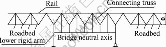
Fig. 1 Bar element to simulate resistance and frame with rigid arms to simulate beam
Based on Fig. 1, the vertical rigid member was canceled. By calculating the flexural force, the load was directly applied to the neutral axis of the beam. Owing to the reasonable simulation of the top and bottom flange rigid arms, the calculation error was small. The beam element simulation was used for the rail, the beam element simulation with rigid arm was used for beam body, the equivalent linear spring simulation was used for the rigid pier, the nonlinear bar element simulation was used for the joins between track and bridge or roadbed, and the German ideal elastic-plastic model parameters were used for the longitudinal resistance model. For the ballast track, unloaded line was 20 kN/m per line, loaded line was 60 kN/m per line, and when the relative displacement was 2 mm, the slip happened. In order to more accurately simulate the characteristics of the single load and double-track railway, the space module was used, as shown in Fig. 2.
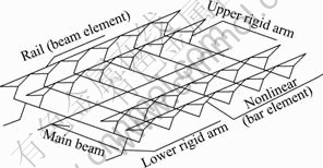
Fig. 2 Schematic diagram of finite element model (partial)
The parameters of the 32 m double-line standard simply-supported beam for the Chinese high-speed railway (deck was 12.6 m wide) were used, and the continuous beam cross-section is shown in Fig. 3.
The bridge span arrangement is shown in Fig. 4. The alternate arrangement of fixed bearing and movable bearing was used for simply-supported beam bearings. The fixed bearing was set up in the middle of bridge pier for continuous beam, and from left to right, rigid pier numbers were No. 1- No. 10. Among them, No. 1 was the rigid abutment, No. 10 was the rigid pier of the continuous beam and No. 2- No. 9 were the rigid piers of the simply-supported beams.
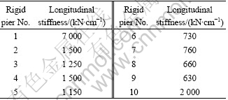
The great impact on longitudinal forces was made by the pier stiffness. When calculating the track stress, the actual stiffness was taken for the pier stiffness, as listed in Table 1. The pier stiffness of shifting bearing was not considered.
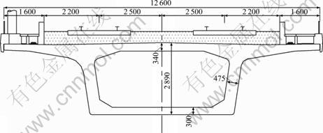
Fig. 3 Standard section of continuous beam (Unit: mm)
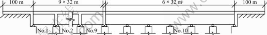
Fig. 4 Span arrangement (9-32 m simply-supported beam + 6��32 m continuous beam)
Table 1 Rigid pier stiffness
The most unfavorable load was used for the braking force (single line brake), 0.164 [11] was used for wheel-rail adhesion coefficient, ZK live load was used for live load [13], and load length was 400 m [14], braking back at the left end of the bridge.
For the variation range of beam, increasing- temperature for the concrete beam of ballast track was 15 ��C [15]. When calculating the flexural force, the live load covered on double-track and full-bridge.
4 Analysis of beam-track interaction with ballast track
The purpose of studying the beam-track interaction was to determine the longitudinal force stressed in the bridge substructure to ensure the stressed track within security and to make sure that the beam-track relative displacement did not beyond its limit [16].
By calculating, it was found that the rail braking stress and expansion stress were main guideposts. Both the braking stress and expansion stress on the continuous beam rail were large, and the maxima of braking compressive stress and expansion compressive stress appeared at the joint between continuous beam and remote abutment, which became the most unfavorable position of stressed rail. However, the rail flexural stress within the continuous beam was very small, as shown in Fig. 5.

Fig. 5 Rail stress distribution map
The braking force for the continuous beam rigid before being carried was far greater than the expansion force and flexural force. For simply-supported beam abutment, both the stressed braking force and expansion force were larger and nearer, while the flexural force was relatively less. For the rigid piers (No. 7-No. 9) near the continuous beam, both the braking force and expansion force were large, and the impact of other piers was mainly made by the braking force, as shown in Fig. 6.
And in Fig. 7, it is shown that the distribution rule of beam-track relative displacement corresponded with that of rail braking stress (absolute value), the maximum of which appeared at the joint between the continuous beam and distal abutment.
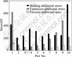
Fig. 6 Comparison of pier stress
5 Factors of beam-track interaction
5.1 Line longitudinal resistance
The longitudinal resistance was the clear indicator to show the intensity of track bed and fastener restricting the track, and it was also the most important parameter calculating the rail longitudinal force. The impact of longitudinal resistance on the rail force, pier force and beam-track relative displacement were calculated. The results obtained in the calculation are shown in Fig. 8.
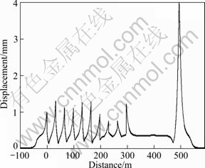
Fig. 7 Beam-track relative displacement distribution
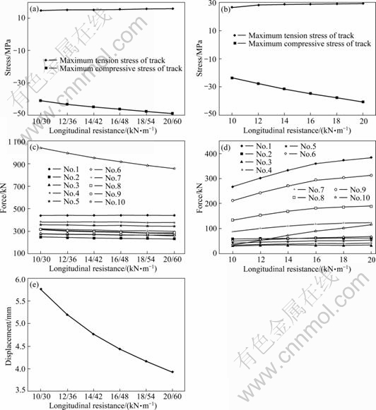
Fig. 8 Rail force and relative displacement varying with longitudinal resistance: (a) Maximum of braking rail additional stress; (b) Maximum of expansion rail additional stress; (c) Pier brake additional force; (d) Pier expansion additional force; (e) Maximum of beam-track fast relative displacement
It was found by the analysis that both the tension stress of rail brake and expansion stress had a small increase with increasing the longitudinal resistance, while compressive stress increased more rapidly. Increasing the longitudinal resistance overall made the smaller impact on longitudinal force of continuous beam rigid pier, but could more substantially increase the longitudinal force on the rigid piers of simply-supported bridge abutment and continuous beam. In addition, the impact on the beam-track relative displacement could be effectively reduced by increasing the longitudinal resistance.
5.2 Longitudinal stiffness of continuous beam rigid pier
It was shown that the longitudinal stiffness of the bridge pier was the most important factor to influence the longitudinal force transmission. In the process of the beam-track interaction, the braking force, expansion force and flexural force made the bridge infrastructure generate the longitudinal displacement, while the infrastructure displacement conversely gave load to CWR on bridge, so as to cause the re-distribution of the rail force. The impacts of the rigid pier stiffness of continuous beam on the stress of the rail and pier and the beam-track relative displacement are shown in Fig. 9.
5.3 Longitudinal stiffness of simply-supported beam rigid pier
The impacts of rigid pier rigidity of continuous beam on the rail and pier force and the beam-track relative displacement were calculated, as shown in Fig. 10.
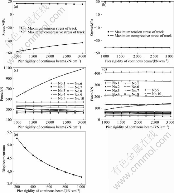
Fig. 9 Stress and beam-track relative displacement varying with rigid pier rigidity of continuous beam: (a) Maximum of rail brake additional stress; (b) Maximum of rail expansion additional stress; (c) Brake additional stress on piers; (d) Expansion additional stress on piers; (e) Maximum of relative beam-track displacement
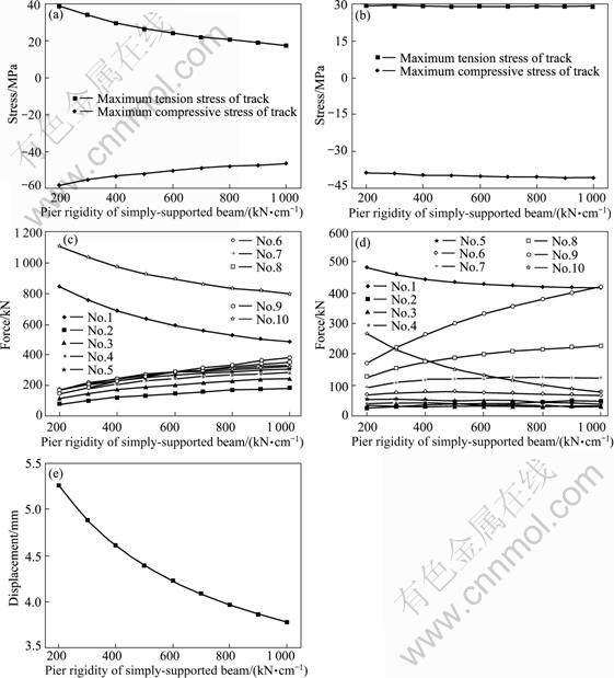
Fig. 10 Stress and beam-track relative displacement varying with rigid pier rigidity of simply-supported beam: (a) Maximum of rail brake additional stress; (b) Maximum of rail expansion additional stress; (c) Brake additional force on piers; (d) Expansion additional force on piers; (e) Maximum of relative beam-track displacement
In Fig. 10, it was shown that the maximum braking stress significantly reduced with increasing the rigid pier rigidity of simply-supported beam, while both the rail expansion stress maximum and flexural stress maximum slightly increased with increasing the rigid pier rigidity of simply-supported beam. Increasing the rigid pier rigidity of simply-supported beam could effectively reduce the longitudinal force for continuous beam rigid pier and simply-supported beam abutment to be stressed. In addition, it could effectively reduce the impact on the beam-track relative displacement.
6 Conclusions
1) For the simply-supported beam rigid pier near continuous beam, the expansion force for it to be stressed is very large. So, both the stiffness setting and bearing selection need to be specially considered under the action of expansion force.
2) Reducing the longitudinal resistance can effectively reduce the maximum rail compressive stress, and can also reduce the pier stress near the continuous beam, but the beam-track relative displacement can increase rapidly.
3) Increasing the rigid pier rigidity of the continuous beam, the rail braking force reduces, the longitudinal force for the rigid pier to be stressed increases and the beam-track relative displacement reduces.
4) Increasing the rigid pier rigidity of the simply-supported beam, the rail braking force reduces, the longitudinal force for the rigid pier to be stressed reduces and the beam-track relative displacement reduces.
References
[1] ZHANG Ye-zhi, ZHANG Min. Structure and behavior of floor system of two super high-speed railway Changjiang composite bridges [J]. Journal of Central South University of Technology, 2011, 18(2): 542-549.
[2] Bridge Research Institute of Railway Bridge Authority. German Standard DS899/59. Special procedures on railway Shinkansen bridge [S]. 1991.
[3] YIN Cun-xin, PAN Jia-ying, ZHUANG Jun-sheng. On nonlinear static and dynamic analysis and emulation of additional forces in railway bridges [J]. China Railway Science, 2001, 22(5): 133-137. (in Chinese).
[4] XU Qing-yuan. Static and dynamic 3D finite element analysis of longitudinal forces transmission between CWR and high-speed railway bridges [D]. Changsha: Central South University, 2005. (in Chinese).
[5] LI Bao-you. Study on longitudinal force of CWR on bridge for speed-raising trunk line steel truss girder [D]. Changsha: Central South University, 2006. (in Chinese).
[6] JIANG Peng. Interaction between girder and rail of rail transit viaduct with U-shape girder [D]. Shanghai: Tongji University, 2008. (in Chinese).
[7] China Academy of Railway Sciences. [2003]205. Railway construction, interim provisions of CWR design on newly built railway bridge [M]. Beijing: China Railway Press, 2003. (in Chinese).
[8] BATTINI J, MAHIR U. A simple finite element to consider the non-linear influence of the ballast on vibrations of railway bridges [J]. Engineering Structures, 2011, 33(9): 2597-2602.
[9] READ D, LOPRESTI J. Management of rail neutral temperature and longitudinal rail forces [J]. Railway Track and Structures, 2005, 101(8): 18-19.
[10] ORE. Braking and acceleration force on bridges-Measurement and evaluation methods [R]. 1970.
[11] BU Yi-zhi. Research on the transmission mechanism of longitudinal force for high-speed railway bridges [D]. Chengdu: Southwest Jiaotong University, 1998. (in Chinese)
[12] BIONDIA B, MUSCOLINOB G, SOFIB A. A substructure approach for the dynamic analysis of train�Ctrack�Cbridge system [J]. Computers & Structures, 2005, 83(11): 2271-2281.
[13] TB10002.1��2005. Fundamental code for design on railway bridge and culvert [S]. Beijing: China Railway Press, 2005. (in Chinese)
[14] LI Ling-ying. Discussion of live load design standards on high-speed railway small and medium span bridge [D]. Changsha: Central South University, 2011. (in Chinese)
[15] Code for railway CWR design (draft) [S]. Beijing: Institute of Economic Planning Ministry of Railways, 2008. (in Chinese)
[16] YAN Bin, DAI Gong-lian. CWR longitudinal force of cable-stayed bridge on high-speed railway [J]. Journal of the China Railway Society, 2012, 34(3): 83-87. (in Chinese)
(Edited by YANG Bing)
Foundation item: Project(50678176) supported by the National Natural Science Foundation of China
Received date: 2011-03-14; Accepted date: 2011-10-19
Corresponding author: YAN Bin, PhD Candidate; Tel: +86-13787799105; E-mail: zhixu1984@gmail.com
Abstract: Based on the construction bridge of Xiamen-Shenzhen high-speed railway (9-32 m simply-supported beam + 6��32 m continuous beam), the pier-beam-track finite element model, where the continuous beam of the ballast track and simply-supported beam are combined with each other, was established. The laws of the track stress, the pier longitudinal stress and the beam-track relative displacement were analyzed. The results show that reducing the longitudinal resistance can effectively reduce the track stress and the pier stress of the continuous beam, and increase the beam-track relative displacement. Increasing the rigid pier stiffness of continuous beam can reduce the track braking stress, increase the pier longitudinal stress and reduce the beam-track relative displacement. Increasing the rigid pier stiffness of simply-supported beam can reduce the track braking stress, the rigid pier longitudinal stress and the beam-track relative displacement.
