

New mining technique with big panels and stopes in deep mine
WANG Yi-ming(������)1, WU Ai-xiang(�Ⱞ��)1, 2, CHEN Xue-song(��ѧ��)1,
YANG Bao-hua(���)1, SU Yong-ding(������)1
1. School of Resource and Safety Engineering, Central South University, Changsha 410083, China;
2. School of Civil and Environment Engineering, Beijing University of Science and Technology,Beijing 100083, China
Received 2 April 2007; accepted 9 July 2007
Abstract:
For the purpose to suit the bad mining technical conditions, such as deep imbed, gentle dip angle, and high initial stress in Dongguashan deposit, the stoping scheme was optimized. The new mining technique, with temporary curtain walls, large panels and stopes, was achieved as well. The deposit model, which was built through the DATAMINE, was led into FLAC3D for numerical simulation. Based on these, the stabilities of pillars and stopes were analyzed. On the other hand, the impact of output stability by new scheme was verified with the help of optimization planning theory. The results show that stopes and curtain walls are safe when the width of temporary curtain walls between panels are 18 m. The length and width of stope increase to 78 m (82 m) and 18 m respectively, and those of panel increase to 300-500 m and 100 m respectively. The commercial test indicates that the new scheme can attain the aims of simpler production organization, better stope ventilation and work condition, smaller quantities of development and cutting, and 2/3 of equipments as before with the stable output. The pillar stoping technique is credible and valuable.
Key words:
deep well; high initial stress; stoping scheme; optimization;
1 Introduction
The increase of mining depth is a tendency in the future because of the gradual decrease of shallow resources[1-2]. There are a series of problems, such as high stress, high ground temperature, ventilation and drainage, with the increase of mining depth. The shock stress and rock burst are the common problems which are widely concerned[3-12]. The deep metal deposits have been exploited latterly in China, thus only discussion of mining techniques have been carried out before due to the poor testing condition in-situ[13-20].
Dongguashan copper mine is one of the first mental deposits bedding underground more than 1 000 m. As the deep-seated deposit, it has high stress (the maximum principal stress is 38 MPa), high temperature (39.8 ��), deep shaft (the main shaft is 1 125 m deep), and gentle dip angle. The original stope scheme has many shortages, such as difficult production organization, small panels and stopes, less efficiency of large equipments, poor ventilation system, fluctuation of output, large quantities of stope development and cutting. Thus, it is necessary to research and put forward a new stope scheme about it. The new scheme should be beneficial to controlling ground pressure and rock burst, be good to improve ventilation and work surroundings, be favorable to adapt trackless equipments and be easy for production organization. According to those mentioned above, the new mining technique, stage open and delayed filling stoping mining method with large panels and stopes in the deep mine, was put forward. The new scheme that was practiced in the Dongguashan Copper Mine has been proved effective.
2 Mining technical condition of deposit
The attitude of the main ore-body of Dongguashan Deposit��is bedded and lenticular. Its strike is NE 35?-40?. With the attitude of the strata layer, its dip inclines towards North West or South East. The average grade of the copper ore is 1.02% with an average of 17.6% sulfur. The roof of ore-body is mainly marble; and the bottom is mainly siltstone and quartz diorite. The ore-body mainly consists of pyrrhotite, skarn, pyrite, serpentinite, magnetite etc., in which all of these components contain a little copper. The features of the ore-body are as follows: simple structure, a small quantity of joints and cracks, hard rock with good stability, Protodrakonov scale of hardness from 8 to 16 (f=8-16), deep bedding mainly between 800 m to 1 200 m underground, high rock stress with the maximum principal stress between 30 and 38 MPa and its direction roughly consistent with the strike of ore-body (namely NE-SW), and in-situ rock temperature as high as 30-39.8 ��. The pyrrhotite, siltstone, skarn, quartz diorite all have the tendency to burst under the high stress.
The first exploration area was selected in the ore-body between the exploratory line 50-58 and the length of strike is 400 m with the average width of 450 m. In average, its dip angle is 20? but gentler in the middle as 10?. Its average thickness is 38.1 m. Generally speaking, the mining conditions are rather complicated.
The ore grade is low. The designed production scale is 104 t/a.
3 Stoping scheme
3.1 Original scheme
According to the mining technical condition of deposit, the preliminary design proposed the open and delayed filling stoping mining method, which took the panel as the stoping unit. The size of panel is 150 m in length and 100 m in width, each of which carries 20 stopes with size of 50 m in length and 15 m in width. The layout of panels and stopes is continuous without barrier pillar. The stoping direction among panels is normal to the ore-body strike. The thick part of the ore-body should take priority of stoping. The mining sequence of stopes in panel is ��stoping one and leaving three��, that is to say, Stope 1 should be mined firstly and then Stope 5. According to the thickness of the ore-body, the downward deep hole (d165 mm) or the radial medium-length hole (d76 mm) is chosen to burst the ore. The mined areas are designed to be filled with the cement or full tailings. The original stoping layout is shown in Fig.1.
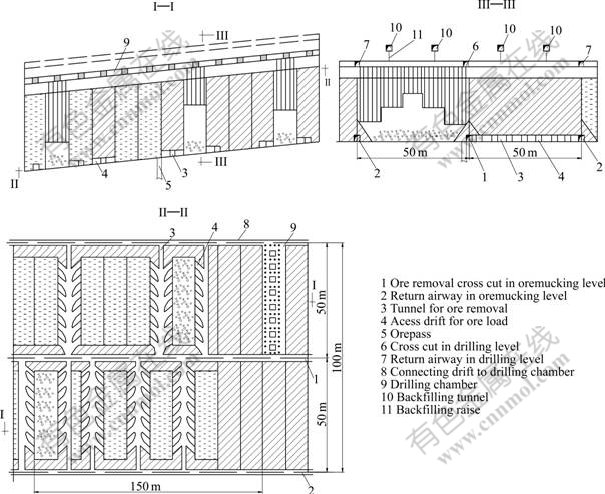
Fig.1 Mining method of preliminary scheme
The problems of the original scheme include:
1) The operation efficiency of large-scale trackless equipment wouldn��t achieve the high level in such small panels and stopes.
2) The original stoping sequence of stopes in panel, ��stoping one and leaving three��, may not be the optimum sequence, because it requires the inter-processes (stope development, loose cutting, drilling, blasting, ore removal and backfilling) of the adjoining stopes either in adjacent panels or in the same panel closely linked. Thus, more stopes and equipments should be on working in order to achieve the required output. Furthermore, according to the original design, the size of each stope should be close. In addition, such strict stoping sequence requires each stope set-up strictly in accordance with the design size and shape to ensure the works quality. However, it is very difficult to do so in practice. But if they do not succeed, this would cause serious ore dilution and loss.
3) According to the original stoping sequence, the thick part of the ore-body is firstly mined. This is not conducive to keep the output stable and make full use of equipments. Because when the stope drilled with deep hole (d165 mm) is recovered first, the drill equipments that are used to drill medium-length hole (d76 mm) stand idle and vice versa.
4) There are too many panels and stopes working at the same time. Thus the ventilation for these working places is much more difficult.
5) For the drilling chamber of the stope with large diameter hole (d165 mm) in the wall rock, too many holes can not be used, and then the drilling cost will be uneconomic.
6) The quantities of stope development and loose cutting is too large, that is 84 m3/kt.
3.2 Stoping scheme after optimization
The optimization scheme is proposed on the basis of keeping the essence of mining method, main development system, output scale and the adopted equipment of the original design. Compared with the original design, the main differences between them are:
1) Change the layout of panels to along the ore-body strike, and increase the parameters of panels with length from previous design to ore-body��s level-width of 100 m;
2) Set barrier pillar between panels and use new stoping sequence ��setting one and stoping one��, that is, mining Stope 1 first and then Stope 3;
3) Replace the stoping sequence of panels to along with the ore-body strike;
4) Increase the size of stope with width increased from 18 m to 15 m and length from 50 m to 78 m (full tailings backfilling) or 82 m (cement backfilling).
5) To control ground pressure, the direction of the stope long axis is set to be coincident with the ore-body strike that is the direction of the principal stress.
The optimization scheme can overcome the problems occurred in the original design effectively. The layout is shown in Fig.2.
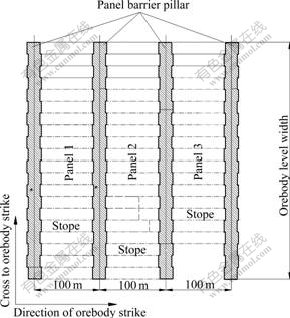
Fig.2 Layout of panels and stopes in optimization scheme
3.3 Issues of optimization scheme
As the structural parameters of stopes and panels are increased in the optimization scheme, the following issues need to be studied further.
1) Under such high in-situ stress conditions of Dongguashan Copper Mine, the stability of the stopes roof and barrier pillars with the tendency of rock burst whether or not meets production safety requirements;
2) After the change of the stoping sequence, the output whether or not keeps smooth and high;
3) How to recovery the barrier pillar efficiently and safely.
3.3.1 Stability of barrier pillars and stopes
To answer the question of pillars and stopes�� stability, the deposit model constructed by DATAMINE was led into FLAC3D with the computer access technology and the stability of pillar and stope in various simulation scheme was analyzed. The deposit model is more identical to the facts and then the results of analysis would be more reliable.
1) Condition of simulation
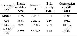
To simplify the simulation process, the ore, rock and backfill body are all considered as homogeneous isotropic body. Their physical and mechanical parameters are obtained by the indoor rock mechanics test but after reduction according to the engineering experience, as listed in Table 1. Mohr-Column criterion is used as the yield condition.
Table 1 Mechanical parameters of ore body and rock mass
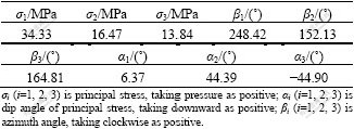
The values of in-situ rock stress are the actual data measured by the Beijing General Research Institute of Mining & Metallurgy in Dongguashan Copper Mine[21], as listed in Table 2.
Table 2 Actual in-situ rock stress values of Dongguanshan Copper Mine
2) Simulation model and scheme
According to the optimization scheme, the options are shown as the following.
Option 1: the width of stope and pillar is 18 m; the length of stope is 90 m; the width of partition pillar is 10 m.
Option 2: the width of stope and pillar is 18 m; the length of stope is 88 m; the width of partition pillar is 12 m.
Option 3: the width of stope and pillar is 18 m; the length of stope is 92 m; the width of partition pillar is 8 m.
Option 4: the width of stope and pillar is 18 m; the length of stope is 84 m; the width of partition pillar is 16 m.
For these four options, the simulation processes are all divided into 5 steps in order to simulate the different stoping states. The details about the simulation processes are shown as follows.
State 1: Stoping 1, 3, 5, 7;
State 2: Stoping 2, 4, 9, 11; backfilling 1, 3, 5, 7;
State 3: Stoping 6, 8, 10, 13; backfilling 2, 4, 9, 11;
State 4: Stoping 12, 15, 17, 19; backfilling 6, 8, 10, 13;
State 5: Stoping 14, 16, 18, 20, backfilling 12, 15, 17, 19.
3) Simulation results
The results show that, with increasing the length and width of stope, the phenomenon of stress concentration becomes a little serious in the stope proof and pillar when using the parameters of Options 1 and 3. In these two options, the maximum value of principal stress is larger by 15%-20% than that using the original design parameters. While, the phenomenon of tensile stress occurs in middle parts of proof and pillars and the maximum value is 4-5 MPa. Thus, the stress state of using the parameters of Options 1 and 3 is a little worse than that of the original design parameters. But from whole aspect, the worse stress state only appears in the parts of the stope proof, so its bad impact is less to worsen the stability of the whole stope. The whole stability of barrier pillars and stopes can be guaranteed during the stoping process.
With increasing the barrier pillar width, the number of units in tensile stress state decreases at the verge of the barrier pillar, and most of their tensile stress is 2-4 MPa. Therefore, it would help to improve the pillar��s stress condition while increasing the barrier pillar width appropriately.
Therefore, to improve the stress condition of the stope and pillar further, the width of barrier pillar adopts 18 m and the corresponding length of stope adopts 82 m in the optimization scheme. In addition, these construction parameters can also meet the safety requirement of exploitation deep mine.
3.3.2 Stability of output
The stability of output depends not only on the continuousness of ore removal, but also on the equipment, staffing related, the number of stopes and stoping sequence. The arrangement of stoping sequence is the most important step to ensure the ore output under the condition that the number of stopes, the number of equipments and workers are minimal on working at the same time.
After the analysis of the mining method and the parameters of various stopes, and then valuating the operation time of various process such as developing and cutting, drilling, blasting, ore-removal, and backfilling, the authors applied the theory of optimization based on Genetic Algorithm, and followed ��a integrated approach from qualitative to quantitative�� to optimize the stoping sequence. Finally, the stope sequence in one panel was determined: when the same process is operated in only one stope, that is to say, when the sizes of stopes are identical, the stoping is started from the thick parts and towards the thin parts. For the panel stoping sequence, there are two panels on working at the same time, and the stoping track is a sloping face like triangle as whole along the ore-body��s strike. Consequently this management can make the structure of panel and output more stable.
Using the stoping process simulation system developed, the following schemes are simulated on the aspect of output stability:
1) the same process operated in three stopes at the same time;
2) the same process operated in four stopes at the same time;
3) four deep or medium hole drilling equipments used at the same time;
4) two deep or medium hole drilling equipments used at the same time.
The simulation results show that, the production of 104 t/d can be achieved when using the scheme that the same process operated in four stopes at the same time. For the optimization scheme, the stability of big scale output can be guaranteed. Because the barrier pillars make the production arrangement more flexible, it can meet the requirement of the same process operated in four stopes between two panels at the same time.
The simulation system and the curve of output��time are shown in Figs.3 and 4, respectively.
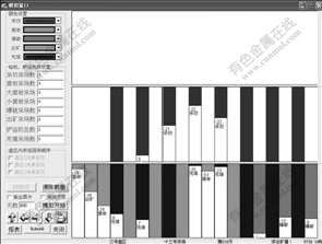
Fig.3 Simulation system
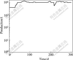
Fig.4 Curve of output��time in optimal scheme
3.3.3 Technology of recovering partition pillar
The partition pillar width is 18 m that is equal to the width of the stope. It cannot only meet the stability requirements of the pillars, but also make the ore pillar recovered safely and smoothly.
1) Mining method
The width of barrier pillar is 18 m and the length is the level width (300-500 m) of ore body. Both sides of it are the stopes filled with the cement or full tailings. Either to control ground pressure easily, or to recover ore safely and to meet the output requirement, the mining method is the same as the method of recovering the main stopes.
2) Stoping sequence
In fact, the barrier pillar is a special panel. It would be recovered after the stopes on both sides are completely mined and filled. The time to recover the first barrier pillar is that the first panel and the second panel are mined and backfilled completely, and the third panel begins to be stoped. The stoping sequence is from the thick part (eastern) to the other end of the ore-body (west).
3) Layout of stope and its construction parameters
Firstly, divide the partition pillar into blocks with length of 36 m and width of 18 m. Secondly, leave a thin ore wall, with length of 18 m and width of 4 m at the end of the block in order to prevent the tailings from interfusion and then decrease the ore dilution. This ore wall will take as permanent pillar, as shown in Fig.5.
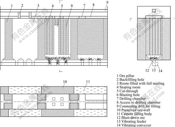
Fig.5 Scheme of pillar recovery
4) Stope development and loose cutting
The main stope developments include ore removal tunnel, drawhole, cutting tunnel, drilling tunnel, drilling chamber, cutting raise, return airway, etc. The tunnels existing in the pillar, such as the passages to drilling chamber, the drifts to ore removal in the stopes, can be fully used.
5) Stoping
�� Drilling and blasting
The equipment for drilling deep hole is T-150 in-the-hole drill. Drill downward vertical or little oblique holes with the diameter of 165 mm in the drill chambers. The hole distribution has arrange space of 3.0 m��3.0 m. The ore blasting form is of terrace-type with height of 8-10 m. Take the cutting chamber as the center and blast the ore with the whole stope wide. The stope roof near the top wall of about 8 m is broken by a one-time blasting.
�� Ore removal
The form of ore gathering tunnel adopts the trench like ��V��. The transportation system consists of vibrating feeder and vibrating continuous conveyer. The broken ore falls into the trench firstly, and then passes through the vibrating feeder to the vibrating conveyer, finally falls into the ore-pass.
�� Ventilation
Firstly, fresh air flows from the air intakes of production levels and ramp loads into the ore removal tunnel, and then carries out the polluted air in the stope through the return airway and discharges to the atmosphere. The ventilation for deep-hole drilling is achieved by the upper level air intakes and return ways. The ventilation for medium hole drilling is a little complex. The fresh air flows from the air intakes of production level and through the cutting raise or filling holes and then carries out the polluted air into the return airways of upper level.
�� Backfilling
After the ore removal is completed, the full tailings filling can be started in mined-area with blocking the reserved ore wall.
When recovering the barrier pillar, the existing stope development tunnels can be fully utilized, so the development and cutting quantities are small. In addition, the mining method to recovery the pillar is experienced and reliable. Thus, the barrier pillars can be recovered safely and efficiently.
4 Conclusions and effect of application
1) In the new scheme, the width of temporary curtain wall is 18 m with length and width of panel increased from 100 m and 150 m to 300-500 m and 100 m, respectively. Those of stope have an increase from 50 m and 15 m to 78 m (tail filling) or 82 m (cement filling) and 18 m. All of them can meet the requirement of high stress deposit in Dongguashan Copper Mine.
2) Temporary curtain walls would make production organization flexible, and the number of drilling and ore drawing equipments are decreased from 6 to 4.
3) The sequence of stoping in panels and stope is adjusted. Only 2 panels and 4 stopes, which are worked at the same time, would be enough to meet the production requirement of 104 t/d.
4) It is established that the test stopes just are production stopes. Thus, the new technique is practiced in the 4 panels of the prior mining area. The stope development and cutting are simplified, and the quantities of them are decreased to 61 m3/kt in practice, far less than that of original design, 84 m3/kt. Now, the output scale reaches 6 000 t/d, and temporary curtain walls and stope roofs are stable, and ventilation and work surroundings are better. The purposes of optimization come true.
5) No-pillar continuous mining method is a tendency of mining underground metal deposits in the future. However, it has a strict requirement of production procedure and stoping sequence, and it is difficult to achieve the large smooth production under the control of the poor equipment and management in China. The mining method and scheme are optimized with optimization theory and numerical simulation technology. It is an innovation to use temporary curtain walls in the large panels and stopes in deep mine. The new scheme is beneficial to controlling ground pressure and rock burst, and making the production and management. This provides a new technique to mine deep deposits in a big scale such as Dongguashan.
References
[1] GU De-sheng. The development tendency of mining science and technology of underground metal mine [J]. The Chinese Journal of Gold, 2004, 25(1): 18-22.
[2] YU Run-cang. Recent science and technology frontier for exploitation of underground metal resources [J]. The Chinese Journal of Engineering Science, 2002, 4(9): 8-11.
[3] LI Shu-lin, FENG Xia-ting, WANG Yong-jia, YANG Nian-ge. Evaluation of rock-burst proneness in a deep hard rock mine [J]. The Chinese Journal of Northeastern University (Natural Science), 2001, 22(1): 60-63.
[4] WU Ai-xiang, HU Hua, YU Jian. Computer simulation and analysis of stope stability for deep mining in Xiangxi Gold Mine [J]. The Chinese Journal of Nonferrous Metals, 1999, 9(4): 846-851. (in Chinese)
[5] DENG Jian, LI Xi-bing, GU De-sheng. Ground pressure and control techniques in non-pillar continuous mining method [J]. The Chinese Journal of Nonferrous Metals, 2001, 11(4): 666-671. (in Chinese)
[6] LIU Jian-qi. Pattern mining and discovery oriented to artificial life [J]. Trans Nonferrous Met Soc China, 1999, 9(4): 847-851.
[7] GRODNER M. Delineation of rock-burst fractures with ground penetrating radar in the Witwatersrand Basin, South Africa [J]. International Journal of Rock Mechanics & Mining Sciences, 2001, 38: 885-891.
[8] SINGH U K, JAIN P N, PRASAD M. Post-pillar behavior at deep levels in a copper mine [J]. International Journal of Rock Mechanism Mining Science & Geo-mechanism Abstract, 1995, 32(6): 585-593.
[9] STEWART R A, REIMOLD W U, CHARLESWORTH E D, ORTLEPP W D. The nature of a deformation zone and fault rock related to a recent rock-burst at Western Deep Levels Gold Mine [J]. Tectonophysics, 2001, 337: 173-190.
[10] LI C C. Disturbance of mining operations to a deep underground workshop [J]. Tunnelling and Underground Space Technology, 2006, 21: 1-8.
[11] GU De-sheng, DENG Jian, LI Xi-bing, ZHANG Jia-sheng. Three dimensional numerical simulation of excavation and backfilling in mining engineering [J]. Trans Nonferrous Met Soc China, 1999, 9(2): 417-421.
[12] TANG Li-zhong, PAN Chang-liang, XIE Xue-bin, CAO Ping. Analysis and prediction of rock burst dangerous areas in Dongguashan Copper Mine under deep well mining [J]. Journal of Central South University of Technology: Science and Technology, 2002, 33(4): 335-338. (in Chinese)
[13] LUO Zhou-quan, ZHOU Ke-ping, GU De-sheng, SHI Xiu-zhi, CHEN Jian-hong, GAO Wen-xiang, DAI Yun-ou, HU Shi-hua, CHEN Xue-yuan, ZHANG Qing-wen. A new mining technology for slightly inclined multi-layer ore bodies [J]. The Chinese Journal of Nonferrous Metals, 2003, 13(3): 760-763. (in Chinese)
[14] DENG Jian, GU De-sheng, LI Xi-bing, PENG Huai-sheng. Energy method and numerical simulation of critical backfill height in no-pillar continuous mining [J]. Trans Nonferrous Met Soc China, 1999, 9(4): 847-851.
[15] YU Jian, DAI Xing-guo, HUANG Ren-dong. The technique of continuous mining and filling in deep well [J]. Journal of Central South University of Technology: Science and Technology, 2000, 31(6): 481-484. (in Chinese)
[16] DENG Jian, GU De-sheng, LI Xi-bin. Reliability analysis of temporary ore wall structure in non-pillar continuous mining [J]. The Chinese Journal of Nonferrous Metals, 2001, 11(4): 671-675. (in Chinese)
[17] JIA Ming-tao, PAN Chang-liang, XIE Xue-bin. The simulation and control of the exploition process in a deeper deposit [J]. The Chinese Journal of Xiangtan Mining Institute, 2003, 18(3): 9-12.
[18] PENG Huai-sheng, GU De-sheng, DE Jian. Technical evaluation of backfill mining method and tentative ideas for backfill stoping in Dongguashan Mine [J]. The Chinese Journal of Mining Research �� Development, 1997, 17(4): 8-12.
[19] WU Ai-xiang, HU Hua. Research of the non-pillar continuous mining technology of underground metal mine [J]. The Chinese of Metal Mine, 2001(10): 9-12.
[20] HE Zhe-xiang, XIE Kai-wei, ZHOU Ai-min. Research and practice of total tailings backfilling [J]. The Chinese Journal of Nonferrous Metals, 1998, 8(4): 739-744. (in Chinese)
[21] QIAO Chun-sheng, TIAN Zhi-you. Preliminary study on in-situ stress field of Dongguashan copper mining area [J]. The Chinese Journal of Nonferrous Mines, 1996(3): 28-32.
Foundation item: Project(2004BA615204) supported by Key Technology Research and Development Program of China; Project(50574099) supported by the National Natural Science Foundation of China
Corresponding author: WANG Yi-ming; Tel: +86-13467700710; E-mail: zhywang@126.com
