
J. Cent. South Univ. (2012) 19: 2482-2487
DOI: 10.1007/s11771-012-1300-2![]()
Kinematics modeling of a 6-PSS parallel mechanism with wide-range flexure hinges
DU Zhi-jiang(��־��), SHI Ruo-chong(ʷ����), DONG Wei(��Ϊ)
State Key Laboratory of Robotics and System (Harbin Institute of Technology), Harbin 150080, China
? Central South University Press and Springer-Verlag Berlin Heidelberg 2012
Abstract:
A novel 6-PSS flexible parallel mechanism was presented, which employed wide-range flexure hinges as passive joints. The proposed mechanism features micron level positioning accuracy over cubic centimeter scale workspace. A three-layer back-propagation (BP) neural network was utilized to the kinematics analysis, in which learning samples containing 1 280 groups of data based on stiffness-matrix method were used to train the BP model. The kinematics performance was accurately calculated by using the constructed BP model with 19 hidden nodes. Compared with the stiffness model, the simulation and numerical results validate that BP model can achieve millisecond level computation time and micron level calculation accuracy. The concept and approach outlined can be extended to a variety of applications.
Key words:
flexible parallel manipulator; wide-range flexure hinge; kinematics model; neural network ��
1 Introduction
With the development of precision engineering, multi-DOF (degree-of-freedom) ultra-precise mechanisms are needed urgently [1-4], which are widely used in microsurgery, biotechnology, micro-assembly and testing of microelectronic circuits. Parallel mechanisms are widely employed in those application areas, due to their advantages of high accuracy, high stiffness and high load capacity and low inertia. However, it is inevitable that backlash and friction exist in the conventional pivots used as passive joints in the parallel mechanisms [5-8]. In order to guarantee the system accuracy, flexure hinges are widely employed in those mechanisms, since they are free of backlash, wear and friction. The adoption of flexure hinges improves the general performances of parallel mechanisms, especially in the systems where precision and resolution are extremely concerned [9-10].
Flexure hinge based parallel mechanisms attract more attention due to the advantages mentioned above. A 6-DOF flexure hinges parallel mechanism was developed by Hanyang University, Korea, to be used in an ultra-precise tele-micro-operation system, which could manipulate an aluminum bean with 20 ��m in diameter successfully aided by micro-vision [11]. YI et al [2] presented a 3-DOF planar flexure hinges parallel mechanism, which was used in micro-manufacture and precise alignment. A 3-RRPR flexure hinge parallel mechanism was developed by YU et al [12], which had the positioning accuracy of 0.02 ��m with close loop control. TIAN et al [13] proposed a mechanical design methodology of a 3-DOF flexure-based mechanism which was utilized to implement planar motions. YUN and LI [14] presented a new 6-DOF 8-PSS/SPS compliant dual redundant parallel robot with wide-range flexure hinges, which achieved both high accurate and rough positioning.
Parallel mechanisms with flexure hinges are utilized in many engineering applications while there is a typical disadvantage in those systems, i.e. an extraordinarily small workspace [15]. In fact, parallel mechanisms based on flexure hinges are destined to obtain a small workspace, because the end-platform displacement is generated by the deformation of flexure hinges. In general applications, the workspace of flexure hinge based parallel mechanisms is limited within cubic micron due to micro deformation of flexure hinges, which imposes restrictions on flexure hinge parallel mechanisms in more applications. Based on this consideration, a 6-PSS parallel mechanism with wide-range flexure hinges is proposed in this work, which achieves micron level positioning accuracy over cubic centimeter scale workspace. The proposed mechanism is suitable for the application which demands large workspace and high resolution simultaneously.
However, there are two notable problems for the applications of wide-range flexure hinges in parallel mechanisms. Firstly, the kinematics analysis of the proposed mechanism is different from the conventional rigid parallel mechanisms or the flexure hinge based parallel mechanisms with small workspace, because wide-range flexure hinges used as passive joints in the system generate relatively large deformation. For the conventional parallel mechanism systems, the kinematics model can be established based on geometric constraints, while the kinematics of proposed mechanism must be modeled based on mechanics approach to examine the influence caused by the deformation of wide-range flexure hinges. Secondly, since the geometric nonlinearity of the system kinematics model caused by global stiffness matrices is quite complicated, it takes relatively long time for the inverse solution [16-17], which does not satisfy the real-time control. Therefore, in order to speed up the solution process, a back-propagation (BP) neural network algorithm is proposed to be applied in the system kinematics analysis.
2 Design descriptions
Flexure hinges are widely employed during the past decades. Several basic types compose the flexure hinges family, which include rotational (Fig. 1(a)), prismatic (Fig. 1(b)) and spherical flexure hinges (Fig. 1(c)). Those flexure hinges can be considered as conventional ones, which are different from the wide-range flexure hinge proposed in this work. It is the basic feature of conventional flexure hinges that motion range is below several hundred microns. Wide-range flexure hinge, as shown in Fig. 1(d) can achieve a motion range on millimeter scale, which extends the application of flexure hinge based parallel mechanisms.

Fig. 1 Flexure hinges family: (a) Rotational flexure hinge; (b) Prismatic flexure hinge; (c) Spherical flexure hinge; (d) Wide-range flexure hinge
The proposed parallel mechanism with wide-range flexure hinges is shown in Fig. 2. The linear joints are actuated by ultrasonic motors, which generate the motions along the linear guides. The input linear motions lead to the deformation of wide-range flexure hinges, which induce the movement of the end-platform. Wide-range flexure hinges in the kinematics chains can provide three-axis rotation, so the proposed mechanism is a 6-PSS system, in which the position and pose of the end-platform are controlled by six inputs. As a typical flexure hinge based mechanism, the proposed system is free of backlash and friction. At the same time, the parallel mechanism also features cubic centimeter level workspace due to employing wide-range flexure hinges. The displacement of the end-platform is contributed by the wide-range flexure hinges, so the description of the deformation of wide-range flexure hinges is the fundamental of kinematics analysis of the integrated system.
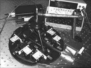
Fig. 2 Picture of proposed parallel mechanism with wide-range flexure hinges
3 Kinematics model based on stiffness model
Many simplified methods are applied to model the conventional ��narrow-range�� flexure hinges [2-3, 18], which are not suitable for this flexible parallel mechanism due to the large deformation characteristics of wide-range flexure hinges. From the perspective of mechanics, the proposed wide-range flexure hinge can be considered as a beam element with large length-to- diameter ratio. If i and j are two nodes of the beam, the distributions of displacements and loads of nodes are represented under the local coordinate, as shown in Fig. 3. The stiffness model can be established as
![]() (1)
(1)
where ![]() ,
, ![]() and
and ![]() are the stiffness matrix, nodal displacement vector and nodal load vector in the local coordinate, respectively.
are the stiffness matrix, nodal displacement vector and nodal load vector in the local coordinate, respectively.
The elements in stiffness matrix ![]() can be expressed as the function of structural and material parameters. In general analysis,
can be expressed as the function of structural and material parameters. In general analysis, ![]() ,
, ![]() and
and ![]() must be transformed to K, d and P in the global coordinate via coordinate transformation matrix. The stiffness model in global coordinate can be formulated as
must be transformed to K, d and P in the global coordinate via coordinate transformation matrix. The stiffness model in global coordinate can be formulated as
K��d=P (2)
 (3)
(3)
![]() (4)
(4)
where K, d, and P are the stiffness matrix, nodal displacement vector and nodal load vector in the global coordinate, respectively; and T is the coordinate trans- formation matrix based on the direction cosine matrix f from the global coordinate to the local coordinate.
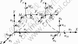
Fig. 3 Wide-range flexure hinges in local coordinate
In the proposed mechanism shown in Fig. 4, other parts except wide-range flexure hinges can be considered as rigid bodies, so the parallel mechanism with wide-range flexure hinges is a rigid-flexible coupled body. In the kinematics analysis, the rigid beam can be modeled as a flexible element with high stiffness, so the kinematics model of proposed parallel mechanism can be integrated via assembling stiffness matrices.

Fig. 4 Kinematics chain of 6-PSS parallel mechanism with wide-range flexure hinges
Under the consideration of integrated modeling, three ��flexible�� beams (flexure hinge x, flexure hinge s and rigid beam g) construct one flexible chain, so a stiffness matrix of the assembled chain can be formulated as
 (5)
(5)
where ![]() ,
,![]() ,
,![]() and
and![]() are the assembled stiffness matrix, sub-block stiffness matrices of the flexure hinge (s), flexure hinge (x) and rigid beam (g) in the global coordinate, respectively.
are the assembled stiffness matrix, sub-block stiffness matrices of the flexure hinge (s), flexure hinge (x) and rigid beam (g) in the global coordinate, respectively.
Therefore, the relationship between nodal displacement and nodal load in one kinematics chain is established via the stiffness equation:
![]() (6)
(6)
where ![]() and
and ![]()
![]() are assembled nodal load column vector and nodal displacement column vector in the global coordinate.
are assembled nodal load column vector and nodal displacement column vector in the global coordinate.
The assembled stiffness matrix KA can be divided into four band sub-matrices:
 (7)
(7)
If the middle two sub-matrices of KA are utilized, the stiffness matrices of the middle two nodes in the kinematics chain can be formulated as
 (8)
(8)
For inverse kinematics, thirteen elements (twelve in d1 and d2, and one in da) in the column vector of twenty-four dimensional nodal displacements are unknown, while via Eq. (8), twelve unknown elements in d1 and d2 can be expressed by the unique unknown element in da. Thus, there is only one unique unknown element in the integrated nodal displacement vector of each kinematics chain, ![]() or
or ![]() which depends on the input along the x-axis or y-axis. Therefore, utilizing Eq. (9), the nodal load of node b can also be expressed by the unknown element:
which depends on the input along the x-axis or y-axis. Therefore, utilizing Eq. (9), the nodal load of node b can also be expressed by the unknown element:
 (9)
(9)
The nodal loads Pb of each chain and external load Pw acting on the end-platform with a balanced condition can be expressed as
![]() (10)
(10)
There are six unknown parameters (![]() ,
, ![]() ,
, ![]() ,
, ![]() ,
, ![]() and
and ![]() ) in Eq. (10), which can be solved in the six algebra equations.
) in Eq. (10), which can be solved in the six algebra equations.
From Eq. (4), it can be seen that the global stiffness matrix can be achieved utilizing the local stiffness matrix and transformation matrix, which leads to the fact that the global stiffness matrix is related to the current position and pose of the beam. This problem can be ignored for conventional flexure hinges, since the transformation matrix can be considered to be constant due to the micro motion of the flexure hinges. However, the flexure hinges move within a large range during the deformation, which cannot be neglected since the transformation matrix is not constant any more. This is a typical geometric nonlinear problem, which features that the stiffness matrices are not constant but the functions of position and pose of elements. For the inverse kinematics modeling, the actuation inputs and position and pose of the wide-range flexure hinges are unknown, so it can be seen that geometric nonlinear problem screws up the kinematics analysis. Iterative method is suitable for solving geometric nonlinear problem, so a strategy based on increment Newton-Raphson approach is proposed for the inverse kinematics solution of parallel mechanism with wide-range flexure hinges.
By using the method mentioned above, the solution of inverse kinematics can be achieved precisely. However, minute-level time will be used to calculate one solution due to the complicated iterative process, which cannot satisfy the real-time control. In order to improve the computation efficiency, a strategy based on BP neural network is proposed for the kinematics model.
4 Kinematics model based on BP neural network
As mentioned above, the solution process of inverse kinematics model is to calculate six actuation inputs according to the six dimensional vectors of the position and pose of end-platform. It can also be considered as a process performing nonlinear mapping from inputs (the position and pose of end-platform) to outputs (six actuation inputs). Therefore, when the computation efficiency based on mechanics approach limits the inverse kinematics solving, back-propagation (BP) neural network can be proposed as an alternative strategy. BP neural network is one of the most popular networks, which is a very powerful tool for nonlinear computation. In this work, a BP network will be utilized in kinematics analysis for parallel mechanism with wide-range flexure hinges, which is expected to improve the computation speed of kinematics solution.
A three-layer BP network is shown in Fig.5, which needs to establish the nonlinear mapping from space Q to space L. The vectors Q (q1 q2 q3 q4 q5 q6) and L (l1 l2 l3 l4 l5 l6) represent position and pose of the end-platform and six actuation inputs, respectively. The application of BP network includes forward propagation process of message and back propagation process of error.

Fig. 5 Three-layer back-propagation neural network model
Generally, the forward propagation process of message includes four steps. In the first step, the input layer of the BP neural network is constructed. In the input layer nodes, the output oi equals the input qi:
oi=qi (11)
In the second step, the relationship between input ij and output oj in the hidden layer node can be established as
![]() (12)
(12)
![]() (13)
(13)
where ��ij is the weight value, ��i is the threshold, and f is the nonlinear sigmoid function.
In the third step, the output layer of the network is constructed. In the output layer nodes, the input ik and output ok can be formulated respectively as
![]() (14)
(14)
![]() (15)
(15)
where ��kj is the weight value, ��k is the threshold, and g is the linear Purelin function.
Finally, it will be estimated if the objective function E is less than expected value based on the learning samples Qp (qp1 �� qp6) and Lp (lp1 �� lp6), where p is the consecutive integers, p=1, 2,��, P.
![]() (16)
(16)
![]() (17)
(17)
In the equations above, tpk and opk are objective output and computation output, respectively. If the objective function E is less than the accepted error ��, the forward propagation of message is ended. The converse will activate the back propagation of error.
During the back propagation process of error, the weights and thresholds will be modified using the equations below, via the gradient descent method:
![]() (18)
(18)
![]() (19)
(19)
![]() (20)
(20)
![]() (21)
(21)
where n is the iterative number of times, �� is the step size, and �� is the inertia coefficient which evaluates the rate of convergence during the learning process.
The accuracy of BP neural network model can be improved by increasing the number of hidden layers or the nodes of hidden layer. However, more layers and nodes will lead to a more complicated model and cost more learning time. In this work, a network with three layers, six input nodes, and six output nodes is selected, as shown in Fig. 5. 1 280 groups of data calculated by stiffness model are used as learning samples to construct the neural network. After 2 000 times learning, the mean squared error achieves 3.63��10-5 mm, and the three-layer BP neural network with 19 hidden nodes can be determined. The learning curve is shown in Fig. 6.

Fig. 6 MSE curve during model learning process
In order to validate the effectiveness of the proposed BP neural network in kinematics analysis, several calculation examples of inverse kinematics model are performed by using the constructed BP model. Table 1 provides the computation results of the proposed parallel mechanism based on stiffness model and BP model, respectively, where the six active actuations are the input for the system and MSE is the mean squared error of BP model relative to stiffness model. It can be seen that MSE range varies on sub-micron level (from 0.000 293 to 0.000 963 mm), which indicates the guarantee of computation precision by using BP model. At the same time, the computation time varies from 0.007 3 to 0.008 7 s based on BP model solution. Therefore, it can be concluded that the time cost utilizing BP neural network reduces sharply from hundreds seconds to several milliseconds, and the MSE indicates that the calculation accuracy can be controlled within micron level. It can be seen that the BP model can realize nonlinear mapping and increase the computation efficiency on the basis of high computation accuracy.
Table 1 Results of comparison between stiffness matrix based model and BP neural network based model

5 Conclusions
1) A 6-PSS flexible parallel mechanism based on wide-range flexure hinges is proposed, which can provide micron-level high precision and centimeter-scale large workspace simultaneously.
2) The stiffness-matrix-based kinematics model of proposed mechanism is established, which fully considers the mechanics behaviors of the wide-range flexure hinges. The geometric nonlinear problem of the kinematics solution can be solved by utilizing Newton-Raphson method.
3) A BP neural network with three layers and nineteen hidden nodes is proposed to improve the computation speed. The validation computation examples show that the proposed BP model can significantly promote the computation efficiency on the basis of maintaining the computation accuracy. The kinematics analysis based neural network can be extended to a variety of applications.
References
[1] ANDO N, KORONDI P, HASHIMOTO H. Development of micro-manipulator and haptic interface for networked micromanipulation [J]. IEEE/ASME Transactions on Mechatronics, 2001, 6(4): 417-427.
[2] YI B J, NA H Y, CHUNG G B, KIM W K, SUH I H. Design and experiment of a 3DOF parallel micro-mechanism utilizing flexure hinges [C]// Proceedings of 2002 IEEE International Conference on Robotics and Automation (ICRA). Washington, USA: IEEE, 2002: 1167-1172.
[3] LINDERMAN R J, BRIGHT V M. Nanometer precision positioning robots utilizing optimized scratch drive actuators [J]. Sensors and Actuators, 2001, 91(3): 292-300.
[4] JUHAS L, VUJANIC A, ADAMOVIC N, NAGY L, BOROVAC B. A platform for micropositioning based on piezo legs [J]. Mechatronics, 2001, 11(7): 869-897.
[5] YANG Chi-fu, ZHENG Shu-tao, JIN Jun, ZHU Si-bin, HAN Jun-wei. Forward kinematics analysis of parallel manipulator using modified global Newton-Raphson method [J]. Journal of Central South University of Technology, 2010, 17(6): 1264-1270.
[6] LIU Shan-zeng, YU Yue-qing, ZHU Zhen-cai, SU Li-ying, LIU Qing-bo. Dynamic modeling and analysis of 3-RRS parallel manipulator with flexible links [J]. Journal of Central South University of Technology, 2010, 17(2): 323-331.
[7] SUN Tao, SONG Yi-min, YAN Kai. Kineto-static analysis of a novel high-speed parallel manipulator with rigid-flexible coupled links [J]. Journal of Central South University of Technology, 2011, 18(3): 593-599.
[8] UCHIYAMA M. Structures and characteristics of parallel manipulators [J]. Advanced Robotics, 1994, 8(6): 545-557.
[9] LI Shi-hua, ZHANG Yue, HUANG Zhen, YU Chang-cheng, DING Wen-hua. Design and analysis of a 3-DOF micromanipulator driven by piezoelectric actuators [C]// Proceedings of the 2008 ASME International Design Engineering Technical Conferences and Information in Engineering Conference. Brooklyn, New York: ASME, 2008: 871-878.
[10] HAO Xiu-qing, CAI Kai-yun, XU Zong-gang, PENG Xue-juan. Design of flexible hinge of micro-vibration platform based on three-translational parallel mechanism [C]// Proceedings of the International Conference on Measuring Technology and Mechatronics Automation 2010. Changsha, China: IEEE, 2010: 993-996.
[11] CHUNG G B, YI B J, SUH I H, KIM W K, CHUNG W K. Design and analysis of a spatial 3-DOF micromanipulator for tele-operation [C]// Proceedings of the International conference on Intelligent Robots and Systems 2001. Maui, HI, USA: IEEE, 2001: 337-342.
[12] YU Jing-jun, BI Shu-sheng, ZONG Guang-hua, YU Bao. Analysis for the static stiffness of a 3DOF parallel compliant micromanipulator [J]. Chinese Journal of Mechanical Engineering, 2002, 38(4): 7-10. (in Chinese)
[13] TIAN Y, SHIRINZADEH B, ZHANG D. Design and dynamics of a 3-DOF flexure-based parallel mechanism for micro/nano manipulation [J]. Microelectronic Engineering, 2010, 87(2): 230-241.
[14] YUN Yuan, LI Yang-ming. Design and analysis of a novel 6-DOF redundant actuated parellel robot with compliant hinges for high precision positioning [J]. Nonlinear Dyn, 2010, 61(4): 829-845.
[15] XU Qing-song, LI Yang-min. A novel design of a 3-PRC translational compliant parallel micromanipulator for nanomanipulation [J]. Robotica, 2006, 24(4): 527-528.
[16] DONG Wei, SUN Li-ning, DU Zhi-jiang. Stiffness research on a high-precision, large-workspace parallel mechanism with compliant joints [J]. Precision Engineering, 2008, 32(3): 222-231.
[17] DONG Wei, SUN Li-ning, DU Zhi-jiang. Design of a precision compliant parallel positioner driven by dual piezoelectric actuators [J]. Sensors and Actuators A: Physical, 2007, 135(1): 250-256.
[18] WANG S C, HIKITA H, KUBO H, ZHAO Y S, HUANG Z, IFUKUBE T. Kinematics and dynamics of a 6 degree-of-freedom fully parallel manipualtor with elastic joints [J]. Mechanism and Machine Theory, 2003, 38(5): 439-461.
(Edited by YANG Bing)
Foundation item: Project(2002AA422260) supported by the National High Technology Research and Development Program of China; Project(2011-6) supported by CAST-HIT Joint Program, China; Project supported by Harbin Institute of Technology (HIT) Overseas Talents Introduction Program, China
Received date: 2011-08-22; Accepted date: 2012-02-22
Corresponding author: DONG Wei, PhD, Associate Professor; Tel: +86-451-86414462-18; E-mail: dongwei@hit.edu.cn
Abstract: A novel 6-PSS flexible parallel mechanism was presented, which employed wide-range flexure hinges as passive joints. The proposed mechanism features micron level positioning accuracy over cubic centimeter scale workspace. A three-layer back-propagation (BP) neural network was utilized to the kinematics analysis, in which learning samples containing 1 280 groups of data based on stiffness-matrix method were used to train the BP model. The kinematics performance was accurately calculated by using the constructed BP model with 19 hidden nodes. Compared with the stiffness model, the simulation and numerical results validate that BP model can achieve millisecond level computation time and micron level calculation accuracy. The concept and approach outlined can be extended to a variety of applications.
