
J. Cent. South Univ. Technol. (2011) 18: 511-520
DOI: 10.1007/s11771-011-0725-3![]()
Long-term stability analysis of large-scale underground plant of Xiangjiaba hydro-power station
XU Wei-ya(������)1, NIE Wei-ping(����ƽ)1, ZHOU Xian-qi(������)2,
SHI Chong(ʯ��)1, WANG Wei(��ΰ)1, FENG Shu-rong(������)3
1. Institute of Geotechnical Engineering, Hohai University, Nanjing 210098, China;
2. Department of Building Engineering, Xiamen University of Technology, Xiamen 361024, China;
3. Mid-South Design and Research Institute, China Hydropower Consulting Group Co., Changsha 410014, China
? Central South University Press and Springer-Verlag Berlin Heidelberg 2011
Abstract:
Numerical analysis of the
Key words:
large-scale underground plant;��
1 Introduction
A number of large-scale water conservancy and hydropower engineering, environmental engineering, geothermal energy, oil and gas exploration projects and nuclear waste storage projects have been constructed around the world. The underground materials storage cavern in Athens, Greece [1], the underground nuclear waste storage cavern in Paris [2], the tunnel excavation of Three Gorges dam project and the South-North Water Transfer project in China are examples. In the meantime, experimental investigations concerning the mechanical properties, seepage properties and long-term stability of rock masses have been carried out in many countries [3]. These include the URL underground in-situ test in Canada [4], the DECOVALEX project in Europe [5] and the Yucca Mountain in-situ tests in USA [6-7]. Rock rheological mechanical properties are closely related to the long-term stability of geotechnical engineering. Long-term observations and measurements of underground caverns have shown that surrounding rocks of many underground caverns are stable in the initial stage of cavitation, but they become instable or collapse with the increase of the time-dependent deformations [8]. For example, in the Tanern highway tunnel in Austria, when it goes through the zone of soft rock mass such as Chlorite, the maximal deformation rate of the surrounding rock after primary support reaches 20 cm/d, and the maximal displacement reaches 120 mm. The surrounding rocks of underground cavern was under high risk of failure. After modifying the design, the tunnel was finally stabilized and the convergence time of deformation of the tunnel is up to 300 to 400 d [9]. For the earliest tunnels constructed by the New Austrian Tunneling Method (NATM) in China, including Xiakeng, Nanling, Wuzhuang, Wangling and Lingqian tunnel, it is observed that the stress and deformation of their lining structure increase year by year within 2-6 years [10]. It is shown that rock rheology is a process that the mineral configuration of a rock is adjusted and the stress and strain in the rock are changed with time [11].
The rheological characteristics could not be described only by elasto-plastic theory, and new model and method are required. For example, HE et al [12] employed the visco-elasto-plastic constitutive model to simulate the material non-linearity of soil skeleton and chose the updated Lagrange formulation to describe the geometry non-linearity of soft soil. YAHYA et al [13] improved the rheological constitutive model proposed by AUBERTIN in order to better describe the characteristics of plasticity, creep deformation and relaxation. The continuum damage mechanics theory was adopted by LUX and HOU [14] to study the rheological model of LUBBY. A new rheological constitutive model was proposed, and the model was applied to the storage engineering of radioactivity wastes. SU et al [15] tried to determine the structure and parameters of a rheological constitutive model for rocks using a new method based on differential evolution algorithm combined with FLAC3D. ZHOU et al [16] proposed a unified approach for the modeling of elasto-plastic and visco-plastic behaviour coupled with induced damage within the unique constitutive model in quasi-brittle rocks.
Based on the previous studies and the experimental results, the software ANSYS10.0 is applied to establish a three-dimensional finite element model in this work. The confining pressure coefficient method is used to impose ground stress on the underground plant engineering region. With respect to the complicated engineering geology conditions in the site of Xiangjiaba hydro-power station, the rheological analysis is carried out to study the optimal time for supporting and the long-term stability of the surrounding rock masses in the large-scale underground plant of the station in order to meet the requirements of the construction and design.
2 Introduction of Xiangjiaba hydro-power station project
The underground hydro-power system of Xiangjiaba hydro-power station is located in the right bank of dam. The scale of the main plant lists top position in the world, and the cavern excavation span is No.1 among those hydro-power stations constructed, being constructed or to be constructed.
As mentioned above, it is very huge in the scale and the excavation span of the main caverns of the underground plant. In addition, such weakened rock zones as T32-5 which are composed of argillaceous rocks, broken interlayers, broken intercalated gouge layers and mudded intercalations are distributed continuously or discretely in the caverns. Weakened interlays, e.g. JC2-2, JC2-3 and JC2-4, are also distributed in bulk in the exposure of the plant. The soft interlayers, which constitute the unfavorable boundary of the underground plant, may lead to large deformations of the surrounding rock masses, which is extremely detrimental to the stability of the surrounding rock masses during the construction and operation periods. Therefore, it is very necessary to study the long-term stability of the large- scale underground caverns of Xiangjiaba hydro-power station in order to ensure that the underground cavern can work properly.
3 Long-term strength
Long-term strength means the ability of keeping the maximum stress of rockmass in the long-term stress or deformation field. Using simple shear apparatus, torsion gravimeter or stress relaxation instrument, it can be determined by turning points of stress-deformation curves obtained from these tests proposed by CHENG [17].
The long-term strength of sandstone as a example is identified by the break points on the stress deviation- deformation curves under different confining pressures of 3, 5 and 7 MPa in the rheological load tests, and the long-term modulus of the sample is identified by the stress-deformation curves in the first step rheological loading. The results of the two parameters mentioned above are presented in Table 1.
Table 1 Long-term strength and long-term modulus of sandrock
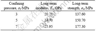
The long-term strength (��1)-confining pressure (��3) curve (Fig.1) is obtained by plotting the long-term strength points of sandstone under different confining pressures. Adopting the least square method, the best fitted equation of the curve is
![]() (R2=0.96) (1)
(R2=0.96) (1)
where R2 is the correlation coefficient, and ![]()
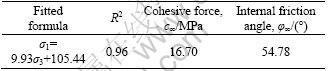
Under complex stress conditions, by using the Mohr-Coulomb failure criteria, the ��1-��3 equation can be expressed as
![]() (2)
(2)
The long-term shear strength parameters of sandstone (c�� and ����) can be determined by Eqs.(1) and (2) (Table 2).
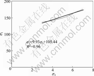
Fig.1 ��1-��3 relation curve regressed by long-term strengths
Table 2 Rheological mechanical parameters of sandstone in triaxial compression
4 Visco-elasto-plastic rheological constitutive model
According to the stress-strain curves of the sandstones, silty mudstones and soft interlayers, a few important regulations are obtained as follows.
1) In terms of instantaneous deformation, elastic deformation characteristic is manifest for the sandstones, elasto-plastic characteristic for the silty mudstones and plasto-elastic characteristic for the soft plastic interlayers.
2) In terms of time-dependent deformation, rheological characteristic is fairly manifest for the soft interlayers, and it is less manifest for the silty mudstones, and least for the sandstones. Under the condition of high stress levels, the three kinds of rock all possess the characteristics of visco-elastic and visco-plastic behaviors.
Thus, a visco-elasto-plastic model is adopted to simulate the time-dependent behaviors of the underground plant cavern groups of Xiangjiaba hydro- power station. The model based on the Burgers visco- elastic model which is coupled with the Mohr-Coulomb plastic yield criteria is presented in Fig.2. In the model, GK is the shear modulus, ��K is the Kelvin viscosity coefficient, GM is the Maxwell shear modulus and ��M is Maxwell viscosity coefficient. The surrounding rock masses classified in accordance with the lithology in the site of Xiangjiaba underground plant are listed in Table 3.
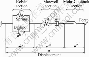
Fig.2 Proposed visco-elasto-plastic model
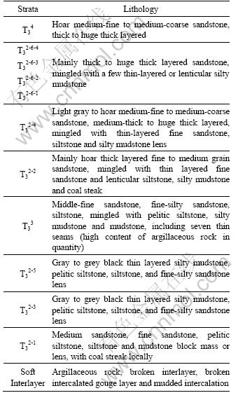
Table 3 Classification of strata
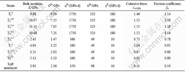
The mechanical parameters of the rheological constitutive model of each rock group, as listed in Table 4, are obtained by triaxial creep test. The creep tests were conducted on the samples with natural water content. Average values are used for the determination of parameters by taking into account of various confining pressures and deviatoric stress levels. The shear creep test results are used to identify the parameters of soft interlayers, and the shear strain equation is described as
![]() (3)
(3)
 (4)
(4)
Table 4 Visco-elasto-plastic model parameters of strata
The triaxial compression creep test results are adopted to identify the parameters of other rock groups, and the axial deviatoric strain equation is described as
![]() (5)
(5)
 (6)
(6)
where E1 and E2 are the elastic modulus, ��1 and ��2 are the viscosity coefficients, ��0 is the initial shear stress, ��0 is the axial deviatoric stress and t is the rheologic time.
5 Criteria
5.1 Criteria for optimal supporting time
At present, the NATM is the popular method in the design and construction of underground engineering. The optimal supporting time criteria of surrounding rock masses are given as follows.
1) The convergence rate of horizontal displacement of the side wall of the cavern must be less than 0.2 mm/d, the rate of vertical displacement of the top arch or the foundation slab must be less than 0.1 mm/d and the creep rate must be decreased significantly [18].
2) The creep displacement must exceed 90% of the total displacement in comparison with similar engineering experiences.
If both of the above criteria are simultaneously satisfied, the corresponding time is the optimal supporting time of the surrounding rock masses at the corresponding excavation step.
5.2 Long-term stability index criteria
The long-term stability creep time and the maximum creep deformation are two important indexes in the long-term stability analysis of large-scale underground caverns. Based on the rheological theory, the two index criteria are proposed as follows.
1) The creep rate is considered to be zero when the surrounding rock masses reach long-term stability, and the corresponding time can be regarded as the creep time of long-term stability.
2) The deformation-time fitting function will tend to be a constant value when the rheological time is long enough, thus the constant value can be considered as the maximum creep deformation of the feature point.
6 3-D finite element rheological calculation
6.1 Establishment of model
According to the experiences and calculation requirements, the model range for three-dimensional numerical calculation of the large-scale underground plant of Xiangjiaba hydro-power station is shown in Fig.3. The length in the X axis direction (lateral direction of the main plant, positive for the upstream direction) is 350.00 m, the length in the Y axis direction (longitudinal direction of the main plant, positive for the mountain inner direction) is 550.00 m, and the height in the Z axis direction (vertical direction, positive for upward direction) is 550.00 m (Notice that the elevation of the bottom surface in the Z axis direction is 0.00 m, and the elevation of the mountain extends to 550.00 m).
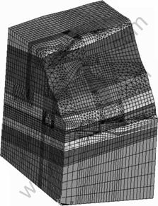
Fig.3 3-D numerical model
The geological lithology strata from up to down can be divided into several layers named T34, T33, T32-6-4, T32-6-3, T32-6-2, T32-6-1, T32-5, T32-4, T32-3 and T32-2 in terms of the lithology description of the rock masses. Four kinds of level �� soft interlayer named JC2-1, JC2-2, JC2-3 and JC2-4 are shown in Fig.4. Major branch tunnels, such as No.1, No.3 and No.5 working branch tunnels, the air tunnel and the traffic tunnel are shown in Fig.5.
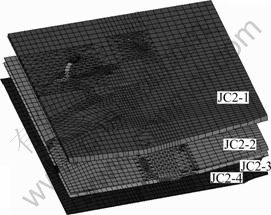
Fig.4 Weak dissections of underground plant region
6.2 Caverns excavation steps
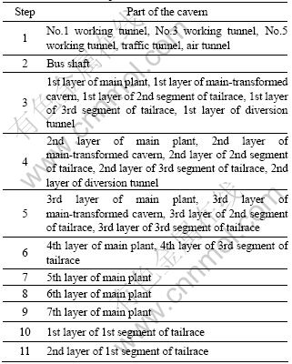
In accordance with the excavation data, the excavation of the main plant is merged into seven steps, and the excavation steps of the other caverns are determined by the actual excavation conditions. There are eleven excavation steps in the project in all, as shown in Table 5. The actual excavation steps of caverns are illustrated in Fig.6 and the schematic diagram of the three-dimensional numerical model excavation is illustrated in Fig.7.
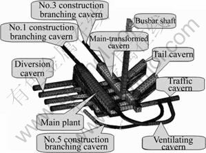
Fig.5 Main caverns and branching caverns of underground plant region
Table 5 Excavation steps of caverns
6.3 Supporting types of caverns
The underground caverns are divided into three major supporting types: the anchor bolt, the anchor cable and the concrete lining, as illustrated in Fig.8. The above three supporting types should be timely applied in accordance with the actual construction conditions in combination with the optimal supporting time.
6.4 Rheological calculation procedures
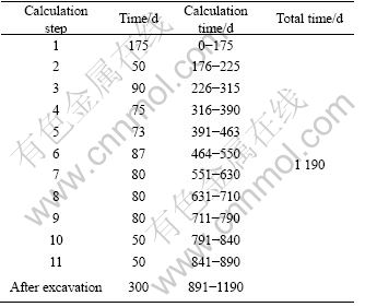
Actual excavation time is adopted for the rheological time after each excavation. The adopted rheological time will last 300 d after the eleventh excavation step of caverns, and the total calculation time would be 1 190 d. The whole rheological calculation plans of caverns are listed in Table 6.
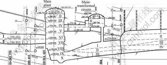
Fig.6 Actual excavation steps of caverns
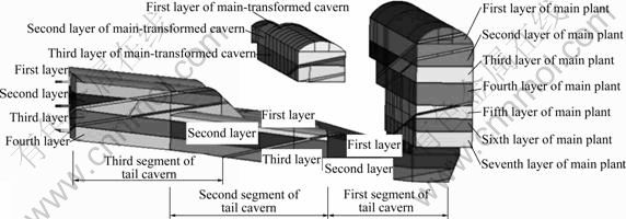
Fig.7 3-D numerical model layers of caverns
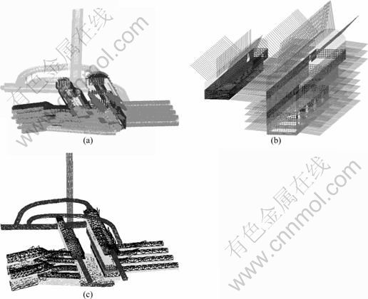
Fig.8 Support forms of caverns in underground plant: (a) Anchor bolt; (b) Anchor cable; (c) Concrete lining
Table 6 Rheological calculation procedures
6.5 Analysis of simulation results
6.5.1 Typical section and feature points
A typical section 1-1 with Y=244.40 m in the middle of the main plant is chosen for a rheological analysis (Fig.9). The distribution of the feature points in the section is illustrated in Fig.10.
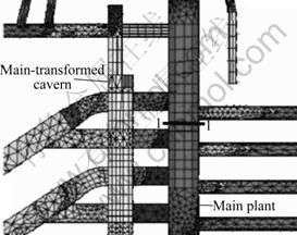
Fig.9 Typical cross section
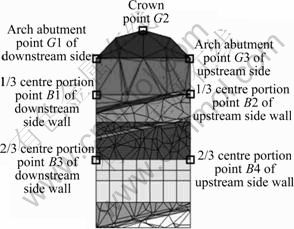
Fig.10 Feature points of typical section
6.5.2 Analysis of optimal supporting time
First, rheological analyses of stepped excavations without supporting are carried out, then the rheological deformations of the feature points in each excavation step are taken for regression analysis (Fig.11), and the rheological rate can be obtained in terms of the corresponding deformation curves and the regression functions.
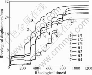
Fig.11 Total displacement curves of feature points without supporting
As the rheological rate and displacement satisfy the optimal supporting time criteria mentioned in 5.1, the optimal supporting time of each excavation step can be obtained. In accordance with the regression analysis, the optimal supporting time of the typical section after each layer excavated is listed in Table 7.
As shown in Table 7, the optimal supporting time is 5-8 d during the excavation process for the typical section.
6.5.3 Analysis of long-term stability creep time and maximum creep deformation
First, the surrounding rock masses of the underground plant are supported at the corresponding moment in accordance with the optimal supporting time identified, then rheological analyses are carried out subsequently, and the total rheological deformation curves of each feature point with supporting are obtained (Fig.12).
The long-term stability creep time and the maximum creep deformation of the typical section can be obtained in accordance with the long-term stability index criteria (Table 8). As shown in Table 8, the maximum creep deformations at the top of the typical section, on the side walls in the upstream and downstream are 21.69, 24.30 and 21.39 mm, respectively, and it will last for 126 d for the section to reach a long-term stability state.
6.5.4 Analysis of supporting effects
Deformations of the surrounding rock masses and the minimum principal stresses under the supporting conditions are compared with those under the non- supporting conditions (Fig.13 and Fig.14).
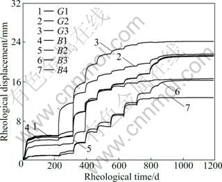
Fig.12 Total displacement curves of feature points with supporting
As shown in Fig.13, under the non-supporting conditions, the maximum deformations at the top of the typical section, on the base plate, on the side walls in the upstream and downstream are 28.43, 18.39, 34.01 and 39.47 mm, respectively; while under the supporting conditions, the deformations at the corresponding positions are 23.24, 15.67, 20.75 and 27.08 mm, respectively, which are 18.26%, 14.79%, 20.38% and 47.43% lower than those under the non-supporting conditions.
As shown in Fig.14, under the non-supporting conditions, the minimum principal stresses at the top of the typical section, on the base plate, on the side walls in the upstream and downstream are 0.40, -1.28, -1.21 and -1.03 MPa, respectively; while under the supporting conditions, the deformations at the corresponding positions are 0.79, -0.66, 1.23 and -0.64 MPa, respectively, which are 97.50%, 48.44%, 37.86% and 201.65% higher than those under the non-supporting conditions.
Table 7 Optimal supporting time of typical section
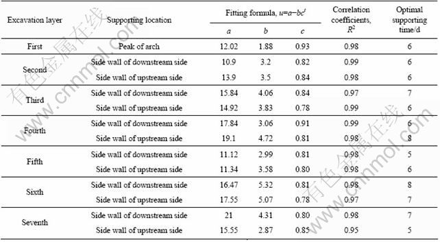
Table 8 Long-term stability creep time and maximum creep deformation of typical section
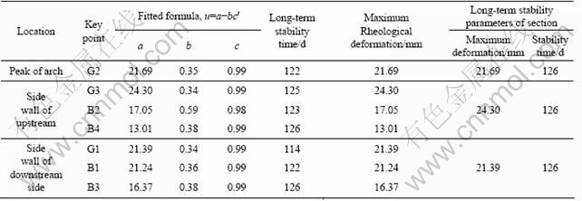
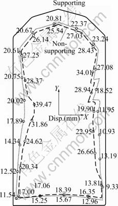
Fig.13 Maximum deformations of surrounding rocks under supporting and non-supporting conditions
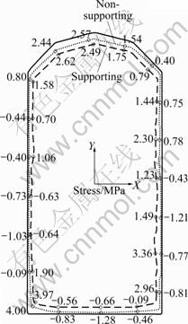
Fig.14 Minimum principal stresses of surrounding rocks under supporting and non-supporting conditions (Positive for compressive stress)
It is very effective in controlling the deformations of the caverns by means of supporting, and the most effective position lies on the side wall in the downstream, where the deformations are relatively less influenced by the excavation of the adjacent caverns. Therefore, supporting the surrounding rock masses at the optimal supporting time is an efficient way to reduce the deformations of the caverns and to improve the stress states of the surrounding rock masses.
7 Conclusions
1) A criterion for the optimal supporting time of surrounding rocks is proposed according to the creep deformation and rate, based on Xianjiaba hydropower station project. The optimal supporting time of a typical section in the large-scale underground plant is determined, that is 5-8 d. Based on the rheological theory, the criteria for long-term stability creep time and the maximum creep deformation are proposed. Using these criteria, the long-term stability creep time for Xiangjiaba project is 126 d, and the maximum creep deformation is 24.30 mm located at the mid-upper part on the side wall of the upstream side.
2) A 3-D finite element calculation has been carried out in which the supporting measures of anchor bolt, anchor cable and shotcrete are taken into account. The analysis follows the sequences of the actual excavation, i.e. supporting while excavating, and the time effects are considered as well. It is shown with the numerical results that, the displacement of the surrounding rock decreases significantly after supporting, by 14.79%-47.43% with respect to the non-supporting condition. On contrast, the minimum principal stresses in the supporting conditions are increased by 37.86%-201.65%, which improves the stress states in the surrounding rock masses. In addition, the reinforcement is most effective on the side wall in the downstream where the deformations are relatively less influenced by the excavation of the adjacent caverns.
3) The rheological analysis has been carried out using the 3-D finite element method. The optimal supporting time, long-term stability creep time and the maximum creep deformation in the large-scale underground plant of Xiangjiaba hydro-power station are obtained.
References
[1] ZEVGOLIS I E, MAVRIKOS A A, KALIAMPAKOSB D C. Construction, storage capacity and economics of an underground warehousing�Clogistics center in Athens, Greece [J]. Tunnelling and Underground Space Technology, 2004, 19: 165-173.
[2] LANDAIS P. Advances in geochemical research for the underground disposal of high-level, long-lived radioactive waste in a clay formation [J]. Journal of Geochemical Exploration, 2006, 88: 32-36.
[3] HOEK E. Practical of rock engineering [M]. London: Institution of Mining and Metallurgy, 2006: 1-18.
[4] READ R S. 20 years of excavation response studies at AECL��s underground research laboratory [J]. International Journal of Rock Mechanics & Mining Sciences, 2004, 41: 1251-1275.
[5] TSANGA C F, JING L, STEPHANSSON O. The DECOVALEX III project: A summary of activities and lessons learned [J]. International Journal of Rock Mechanics & Mining Sciences, 2005, 42: 593-610.
[6] LINA M, KICKERA D, DAMJANAC B. Mechanical degradation of emplacement drifts at Yucca Mountain��A modeling case study. Part I: Nonlithophysal rock [J]. International Journal of Rock Mechanics & Mining Sciences, 2007, 44: 351-367.
[7] DAMJANACA B, BOARDA M, LINB M. Mechanical degradation of emplacement drifts at Yucca Mountain��A modeling case study. Part II: Lithophysal rock [J]. International Journal of Rock Mechanics & Mining Sciences, 2007, 44: 368-399.
[8] ZHOU Wei-yuan. Advanced rock mechanics [M]. Beijing: Water Resources and Electric Power Press, 1990: 173-174. (in Chinese)
[9] DING Xiu-li. Experimental study on rock mass rheological properties and identification for the constitutive model and parameters [D]. Wuhan: Wuhan Institute of Rock & Soil Mechanics, Chinese Academy of Science, 2005: 1-2. (in Chinese)
[10] CHEN Yuan-jiang. Study on the rheological constitutive model of rock and its intelligent identification [D]. Changsha: Central South University, 2003: 1-2. (in Chinese)
[11] ZHAO Yan-lin, CAO Ping, WANG Wei-jun, WAN Wen, LIU Ye-ke. Viscoelasto-plastic rheological experiment under circular increment step load and unload and nonlinear creep model of soft rocks [J]. Journal of Central South University of Technology, 2009, 16(3): 488-494.
[12] HE Qun, WEI Li-min, WANG Yong-he. Application of large strain analysis of visco-elastic-plastic soft soil subgrade [J]. Journal of Central South University: Natural Science Edition, 2009, 40(2): 512-518. (in Chinese)
[13] YAHYA O M L, AUBERTIN M, JULIEN M R. A unified representation of plasticity, creep and relaxation behavior of rock salt [J]. International Journal Rock Mechanics Mining Sciences and Geomeech, 2000, 37: 787-800.
[14] LUX K H, HOU Z. New developments in mechanical safety analysis of repositories in rock salt [C]// Pro Int Conf on Radioactive Waste Disposal, Disposal Technologies & Concepts. Berlin: Springer Verlag, 2000: 281-286.
[15] SU Guo-shao, ZHANG Xiao-fei, CHEN Guang-qiang, FU Xing-yi. Identification of structure and parameters of rheological constitutive model for rocks using differential evolution algorithm [J]. Journal of Central South University of Technology, 2008, 15(sl): 25-28.
[16] ZHOU Hui, JIA Yun, SHAO Jian-fu. A unified elastic-plastic and viscoplastic damage model for quasi-brittle rocks [J]. International Journal of Rock Mechanics & Mining Sciences, 2008, 45(8): 1237- 1251.
[17] CHEN Zong-ji. The mechanical problems for the long-term stability of underground galleries [J]. Chinese Journal of Rock Mechanics and Engineering, 1982, 1(1): 1-20. (in Chinese)
[18] Building research institute of ministry of metallurgy. GBJ86-85 Specifications for bolt-shotcrete support [M]. Beijing: China Communications Press, 1985: 24. (in Chinese)
(Edited by YANG Bing)
Foundation item: Projects(50911130366, 50979030) supported by the National Natural Science Foundation of China; Project(2008BAB29B01) supported by the National Key Technology R&D Program of China
Received date: 2010-04-09; Accepted date: 2010-09-30
Corresponding author: NIE Wei-ping, PhD; Tel: +86-15850599427; E-mail: nwp_jzit@tom.com
