

Friction and wear of 7075 aluminum alloy induced by torsional fretting
CAI Zhen-bing(�����), ZHU Min-hao(��F�), LIN Xiu-zhou(������)
Tribology Research Institute, Traction Power State Key Laboratory, Southwest Jiaotong University,Chengdu 610031, China
Received 17 February 2009; accepted 26 May 2009
Abstract:
The torsional fretting wear tests of 7075 aluminum alloy flat against 52100 steel ball in dry condition were carried out on a new high-precision torsional fretting-wear tester. The kinetics behaviors and damage mechanism of 7075 aluminum alloy under different angular displacement amplitudes were investigated in detail. The results show that the torsional fretting running behaviors of 7075 aluminum alloy can be defined by three fretting regimes (i.e. partial slip regime (PSR), mixed fretting regime (MFR) and slip regime (SR)) with the increase of angular displacement amplitudes. In PSR, the damage occurs at the lateral portion of the contact zone with a slight annular shape. However, in MFR and SR, more severe damages are observed and the debris layer covers the wear scars. Friction torque and dissipation energy which are strongly dependent upon the imposed angular displacement amplitudes and presented in three stages were discussed in detail. The mechanisms of torsional fretting wear of aluminum alloy are mainly oxidative wear, abrasive wear and delamination in the three fretting regimes. In addition, the oxidative debris plays an important role during the torsional fretting wear processes.
Key words:
7075 aluminum alloy; fretting wear; torsional fretting; fretting regime;
1 Introduction
Fretting is a complex process involving the interaction of various physical phenomena between two contact surfaces (friction, wear, abrasion, adhesion, and transfer, etc.) and chemical reactions which occur on the surface and in the subsurface layers. It is defined as the small amplitude oscillatory movement which may occur between two contact surfaces subjected to vibration[1]. Depending upon the loading conditions (relative displacement amplitude and normal load), fretting may cause damage involving crack nucleation, propagation and wear (material loss) induced by debris formation.
Aluminum alloys are excellent materials for industrial, structural and transport applications given their low density, elevated mechanical properties and excellent corrosion resistance. Aircraft industry commonly uses 7xxx series aluminum alloys for aircraft bodies. We know that aging aircrafts suffer from multiple-site fatigue cracking originating from fretting damage. This premature cracking from fretting damage threatens aircraft safety[2].
According to the directions of relative motion, under the contact configuration of ball-on-flat, only four basic fretting modes can be defined: tangential, radial, rotational, and torsional[3]. Whichever fretting wear or fretting-fatigue test is used, the relative motion between two contact solids reported in the literature usually represents reciprocating motion, i.e. the tangential mode. Almost all available literatures on the fretting wear properties for aluminum alloys relate to the tangential mode[4-6]. Especially, the theory of fretting maps (the running-condition fretting map and material-responding fretting map) was built up and consummated based on studies of aluminum alloys[7-8]. Until the present, scholars have conducted little research on other fretting modes, particularly on the torsional fretting mode.
Research groups in UK and China have paid attention to torsional fretting simulation and experimental work. BRISCOE et al found that torsional contact was more detrimental to the wear resistance of polymethyl-methacrylate (PMMA) than that induced by rolling fretting and the interfacial energy induced a preferential debris emission under the torsional contact[9-11]. In our previous researches on Fe-C alloys, tribo-oxidation played an important role in controlling the wear behaviour and wear mechanism, especially in wet air[12-14]. The results from the polymer indicated that crazing and delamination were the major damage mechanisms for PMMA and ultra-high molecular mass polyethylene (UHMMPE)[15-16]. However, knowledge on the torsional fretting behaviors and wear mechanisms for aluminum alloys remain unclear. Thus, in this work, the torsional fretting running behaviors and wear mechanisms of the 7075 aluminum alloy are investigated systematically.
2 Experimental
Torsional fretting wear tests were carried out under a flat-on-ball contact configuration on a new high precision torsional fretting tester as shown in Fig.1[13]. Usually, severe damage occurs under the contact of steel-to-aluminum. Therefore, to expose the damage mechanism significantly, a contact of aluminum alloy flat against a steel ball was used in this study. 7075 alloy (1.6% Cu, 0.4% Si, 0.5% Fe, 0.3% Mn, 2.5% Mg, 5.7% Zn, 0.4% Cr, 0.06% Ti and balance Al (mass fraction); HV 230; Ra=0.05 ��m) was selected as flat specimen. A polished AISI 52100 bearing steel ball with a diameter of 40 mm and hardness of HV 680 served as counter-body during the fretting tests. A constant rotary speed was set as 0.1(?)/s and the torsional angular displacement amplitudes ranged from 0.1? to 10?. A constant normal load of 100 N was imposed during the tests and test cycles varied from 1 to 103. Friction torqueses were monitored by a six-axis force/torque sensor during the whole test. After the fretting wear tests, scanning electron microscope (SEM, Quanta 200) and optical microscope (Zeiss AXIO Imager M1) were employed to observe the surface damage morphologies. A 3-D non-contact surface-mapping profilometer (MicroXAM-3- D, ADE Corp) was used to reconstruct the 3-D morphologies of the wear scars and to measure the maximal depth of wear scars.
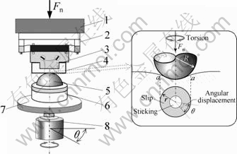
Fig.1 Schematic illustration of torsional fretting wear tester: 1 Six-axis torques/forces sensor; 2 Spring suspension; 3 Upper holder; 4 Flat specimen; 5 Ball specimen; 6 Lower holder; 7 Rotary platform; 8 Low-speed reciprocating rotary motor system
3 Results and discussion
3.1 Kinetic behaviors
For the tangential fretting mode, the friction force on the contact surface was the most basic information obtained from the tests, which was usually controlled by the condition of the displacement amplitude. However, the relative motion direction of the torsional fretting mode differs greatly from that of the tangential mode. Therefore, under the test��s control condition for angular displacement amplitude, the curves of friction torques versus angular displacement amplitudes (T���� curves) were the most basic results gained from the torsional fretting wear tests[13-16].
At a lower angular displacement amplitude of ��=0.1?, closed T���� curves (in shape of a line) appeared consistently during the entire test process (Fig.2(a)), implying that the elastic deformation mainly coordinated the relative motion between the contact interfaces. Under this test condition, the micro-slip occurred at the contact edge and the contact centre was sticking all the time. It can be identified that fretting ran in the partial slip regime (PSR). At a moderate angular displacement (��=0.5?), elliptical T���� curves were transferred to parallelogram loops after 500 cycles (Fig.2(b)) and retained this shape through the succeeding cycles. In other words, the relative motion was transferred from gross slip to partial slip under this test condition. According to the theory of fretting maps, the torsional fretting ran in the regime of mixed fretting (MFR). With the increase of the angular displacement amplitude (��=1? and ��=2?), the fretting still ran in the MFR according to the T���� curves. When �ȡ�5?, the fretting loops presented in the shape of a parallelogram in all cycles (Fig.2(c)) and the torsional fretting ran in status of gross slip. In other words, the fretting run in the slip regime (SR). In SR, the sticking zone disappeared and the wear occurred throughout the entire contact zone.
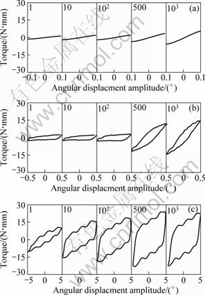
Fig.2 T���� curves of 7075 alloy in different torsional fretting regimes: (a) ��=0.1?, partial slip regime; (b) ��=0.5?, mixed fretting regime; (c) ��=5?, slip regime
The evolution of friction torque in each fretting log was also compared statistically. Fig.3 shows the evolution of friction torques as a function of the number of cycles under various angular displacement amplitudes. Three typical stages can be found for all test conditions. Firstly, at Stage �� the friction torques presented lower values owing to the protection of the adsorbed and polluted surface films. After several decade cycles, the curves entered into Stage �� (ascent stage) when real contact of metal-to-metal formed and the friction torques increased quickly by the adhesion and ploughing. Finally, the torques entered Stage �� (steady state) when the torques varied in a small range and gradually tended to a stable value. From Fig.3, it is clearly that the stable torque values of Stage �� went up with the increase of the angular displacement amplitude. In PSR, a very low stable value appears due to the partial slip between the contact interfaces. In the MFR, the longest Stage �� maybe resulted from the transformation of relative motion status and accompanying of the significant plastic deformation. In SR, the duration of Stage �� and Stage �� was shortened with the increase of the angular displacement amplitude. Obviously, the friction torque was strongly dependent upon the angular displacement amplitude during the torsional fretting mode.
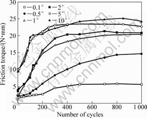
Fig.3 Friction torques of 7075 aluminum alloy under various torsional angular displacement amplitudes
3.2 Friction dissipation energy
We can define friction dissipation energy under torsional fretting conditions mathematically[17]:
![]()
where E is the friction dissipation energy, T is the friction torque, �� is the angular displacement amplitude, in radian. Therefore, the area encircled by the closed T���� curve of each cycle can reveal the friction energy dissipation during the fretting testing.
Fig.4 presents the friction dissipation energy (E) under varied angular displacement amplitudes. In PSR (��=0.1?), E maintained a very low value (almost zero) during the entire test due to the fretting coordinated by the elastic deformation. MFR and SR showed lower values of E in initial cycles (corresponding to Stage �� of the friction-torque curves) due to the protection of the surface film of the two contact bodies. Then, the friction dissipation energy increased in the subsequent cycles (ascent stage) and reached a steady-state stage. The ascent of the friction dissipation energy usually resulted from the plastic deformation of the contact zone. With the debris (the third bodies) forming and taking part in the load-carrying of the fretting process, a balance between the formation and emission of the third bodies was set up, which induced the dissipation energy to gradually reach the steady-state stage. In SR, the duration of the ascent stage was shortened with the increase of angular displacement amplitudes. This accorded with the evolution of the friction-torque curves described in Fig.3. In fact, the variation of the friction dissipation energy was a result of the accumulation of the damage of materials during the fretting process.
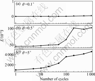
Fig.4 Friction dissipation energy as function of number of cycles, Fn=100 N, cycles=103: (a) ��=0.1?; (b) ��=0.5?; (c) ��=5?
3.3 Wear analyses
For the torsional fretting mode, the worn surface was strongly influenced by the angular displacement amplitudes[13]. When the torsional fretting ran in PSR (��=0.1?), free damage could be found in the center of the scar, where the sticking occurred throughout the entire fretting cycles (Fig.5(a)). Only a slight damage appeared at the contact edge as a result of the lower relative slip between the contact interfaces (Fig.5(b)), which was controlled by the elastic deformation of contact interfaces. Fig.5(b) shows the debris accumulation and particle detachment. The EDX detected slight oxidation at the contact edge. The 3-D image (Fig.5(c)) also shows that only slight damage generated at the edge of the contact zone, and negligible material transfer was detected in PSR.
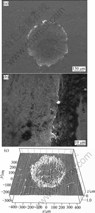
Fig.5 SEM and 3-D images of wear scar in partial slip regime when ��=0.1?, Fn=100 N, cycles=103
In MFR, due to the axisymmetric relative motion for the torsional fretting, slight damage corresponded to the small relative slip at the contact center (Fig.6). In addition, the relative motion status was transformed from gross slip to partial slip in the MFR. This offers another reason why the slight damage appeared at the contact center induced by the sticking. It also induced an annular morphology on the wear scar (Fig.6(a)). A large amount of oxidative debris piled up at the edge of the scar. Detached particles formed a deep pit in the shape of a ring in the middle of the slip zone (Fig.6(c)). In Fig.6(b), slight ploughing along the circumferential direction also can be observed as well. Similar to the condition of the PSR, higher oxidation peaks were detected by EDX. It also explains the partial slip occurred at the latter part of cycles.
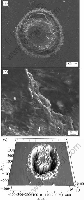
Fig.6 SEM and 3-D images of wear scar in mixed fretting regime when ��=0.5?, Fn=100 N, cycles=103
In SR, the central sticking area disappeared and a gross slip occupied the entire contact zone. Owing to the increase of the relative slip, the debris oxidation increased accordingly, a thick oxidative debris layer (agglomerate debris bed) covered the scar (Fig.7). In addition, detachment by delamination and ploughing by abrasive particles can be observed on the scar. Obviously, the damage morphologies in SR were more severe than those in PSR and MFR. In sum, the wear mechanisms of 7075 aluminum alloy under torsional fretting mode were mainly oxidative wear, abrasive wear and delamination in the three fretting regimes.
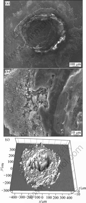
Fig.7 SEM and 3-D images of wear scar in slip regime when ��=5?, Fn=100 N, cycles=103
Fig.8 exhibits the maximal wear depth of the wear scars. It indicates that lower depth values appear in PSR, which is corresponding to slight damage. When the torsional fretting transferred from PSR to MFR and SR, the wear depth increased continuously. In other words, the wear depth increased obviously with the increase of the angular displacement amplitude. It is noteworthy that there was an obvious decline in the wear depth when �� changed from 5? to 10?. This may be owing to the formation of the thick debris bed. The appearance of debris bed may lead to the following factors: 1) It could attribute to the decrease of the real contact area by the participation of load-carrying; 2) The oxidative debris may play a role as a solid lubricant to decrease the wear effectively.
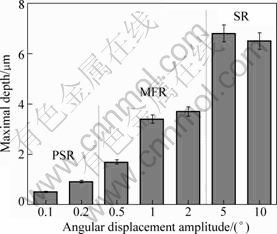
Fig.8 Maximal depth of worn scar as function of angular displacement amplitude: PSR (Partial slip regime); MFR (Mixed fretting regime); SR (Slip regime)
Two points located in non-fretting surface and debris were detected by EDX analysis respectively. The results indicated that there were higher oxygen and less aluminum in wear zone (see Fig.9) compared with that in 7075 alloy original surface. The abundant oxygen apparently came from the oxidative debris. In addition, the element of Fe (from the against counterpair) was found in the upper specimens, which indicated that the debris may include many kinds of oxidation.
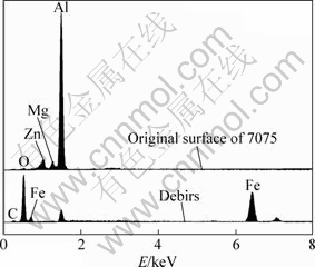
Fig.9 EDX spectra of original 7075 surface and debris
As mentioned above, 7075 aluminum alloy revealed more severe damage in the SR compared with that in MFR and PSR. It can draw an important conclusion that the oxidative debris played an important role during the torsional-fretting wear processes. The results of this study indicate that the debris may protect the original surface against torsional-fretting wear.
4 Conclusions
1) According to the T���� curves and damage morphologies, three fretting running regimes for the torsional fretting of 7075 aluminum alloy can be determined, i.e. partial slip regime (PSR), mixed fretting regime (MFR) and slip regime (SR).
2) The evolution of friction torque and friction dissipation energy appeared in three stages as a function of the number of cycles: initial stage, ascent stage and steady-state stage. In PSR, the friction torque and dissipation energy presented lower values due to the relative motion coordinated by the elastic deformation of contact interfaces. With the increase of the angular displacement amplitude, the friction torque and dissipation energy increased accordingly.
3) The wear mechanisms of 7075 alloy under the torsional fretting conditions were mainly oxidative wear, abrasive wear and delamination in all fretting regimes. Slight damage in shape of annular occurred in PSR. More severe damage occurred and a debris layer covered the scar in MFR and SR. With the increase of the angular displacement amplitude, the depth of wear scars increased accordingly.
4) Oxidative debris played a very important role during the torsional fretting wear processes and reduced wear in SR.
References
[1] ELLEUCH K, FOUVRY S. Experimental and modeling aspects of abrasive wear of a A357 aluminum alloy under gross slip fretting conditions [J]. Wear, 2005, 258(1/4): 40-49.
[2] MU?OZ S, PROUDHON H., DOM?NGUEZ J, FOUVRY S. Prediction of the crack extension under fretting wear loading conditions [J]. International Journal of Fatigue, 2006, 28(12): 1769-1779.
[3] ZHU M H, ZHOU Z R. Dual-motion fretting wear behaviour of 7075 aluminium alloy [J]. Wear, 2003, 255(1): 269-275.
[4] ZHOU Z R, FAYEULLE S, VINCENT L. Cracking behaviour of various aluminum alloy during fretting wear [J]. Wear, 1992,155(2): 317-330.
[5] ZHANG Xin-ming, LI Hui-jie, LI Hui-zhong. Dynamic property evaluation of aluminum alloy 2519A by split Hopkinson pressure bar [J]. Transactions of Nonferrous Metals Society of China, 2008, 18(1): 1-5.
[6] TU Chuan-jun, CHEN Zhen-hua, CHEN Ding, YAN Hong-ge, HE Feng-yi. Tribological behavior and wear mechanism of resin-matrix contact strip against copper with electrical current [J]. Transactions of Nonferrous Metals Society of China, 2008,18(5): 1157-1163.
[7] ZHOU Z R, VINCENT L. Mixed fretting regime [J]. Wear, 1995, 181/183(2): 531-536.
[8] ZHOU Z R, VINCENT L. Effect of external loading on wear maps of aluminum alloys [J]. Wear, 1993, 162/164: 619-623.
[9] BRISCOE J, CHATEAUMINOIS A, LINDLEY T C, PARONAGE D. Fretting wear behaviour of polymethyl-methacrylate under linear motions and torsional contact conditions [J]. Tribology International, 1998, 31(11): 701-711.
[10] BRISCOE J, CHATEAUMINOIS A, LINDLEY T C, PARONAGE D. Contact damage of poly (methylmethacrylate) during complex microdisplacements [J]. Wear, 2000, 240(1/2): 27-39.
[11] BRISCOE J, CHATEAUMINOIS A. Measurements of friction- induced surface strains in a steel/polymer contact [J]. Tribology International, 2002, 35: 245-254.
[12] CAI Zhen-bing, ZHU Min-hao, YU Jia, ZHOU Zhong-rong, An experimental investigation and simulation of torsional fretting mode [J]. Tribology, 2008, 28(1): 18-22. (in Chinese)
[13] CAI Zhen-bing, ZHU Min-hao, SHEN Huo-ming, ZHOU Zhong-rong, JUN Xue-song. Torsional fretting wear behaviors of 7075 aluminum alloy in various relative humidity environment [J]. Wear, 2009, 267: 330-339.
[14] CAI Zhen-bing, ZHU Min-hao, ZHENG Jian-feng, JIN Xue-song, ZHOU Zhong-rong. Torsional fretting behaviors of LZ50 steel in ambient air and nitrogen [J]. Tribology International, 2009, 42(11/12): 1676-1683.
[15] YU Jia, CAI Zhen-bing, ZHU Min-hao, et al. Study on torsional fretting behavior of UHMWPE [J]. Applied Surface Science, 2008, 225(2): 616-618.
[16] CAI Zhen-bing, GAO Shan-shan, HE Li-ping, ZHU Min-hao. Study on torsional fretting characterization of polymethyl-methacrylate [J]. Journal of Sichuan University: Engineering Science Edition, 2009, 41(1): 96-100. (in Chinese)
[17] MEIBOOM S, HEWITT R C. Rotational viscosity in the smectic phases of terephthal- bis-butylaniline (TBBA) [J]. Physical Review A, 1977, 15(6): 2444-2453.
Foundation item: Project(2007CB714704) supported by the National Basic Research Program of China; Projects(50775192, 50821063) supported by the National Natural Science Foundation of China
Corresponding author: ZHU Min-hao; Tel: +86-28-87601304; E-mail: zhuminhao@swjtu.cn
DOI: 10.1016/S1003-6326(09)60148-5
