
Trans. Nonferrous Met. Soc. China 26(2016) 2586-2594
Effect of welding parameters on semisolid stir welding of Mg-9Al-1Zn magnesium alloy
V. A. HOSSEINI1, H. AASHURI2, A. H. KOKABI2
1. Department of Engineering Science, University West, SE-461 86  , Sweden;
2. Materials Science and Engineering Department, Sharif University of Technology, Azadi Ave., Tehran, Iran
Received 17 November 2015; accepted 8 April 2016
Abstract:
Semisolid stir welding of AZ91 was investigated with focus on the joining temperature and rotational speed. An Mg-25%Zn interlayer was located between two AZ91 pieces and the system was heated up to the semisolid state of base metal and interlayer. The weld seam was stirred using a drill-tip at different joining temperatures and rotational speeds. Optical and scanning electron microscopes were employed to study microstructure, cavity formation, and segregation. Hardness profile and shear punch test were also employed to rank the welds based on their quality and homogeneity. Results showed that the lowest cavity content (2.1%) with the maximum ultimate shear strength (about 188 MPa) was obtained in weld with the joining temperature of 530 ��C and the rotational speed of 1600 r/min. Low quality welds and a reduction of ultimate shear strength were observed at very high or low rotational speeds and joining temperatures. The process, in conclusion, produced close mechanical properties to those of the base metal and homogenous quality throughout the joint, when the intermediate temperature and rotational speeds were employed.
Key words:
Mg-Al-Zn alloy; mechanical stirring; semisolid stir welding;
1 Introduction
MENDEZ et al [1] proposed a novel method to join a Sn-15%Pb alloy using a semisolid Sn-5%Pb alloy. They proposed to join metal using a semisolid slurry to solve some problems appearing in fusion welding, such as hot cracking, high residual stresses, spattering and high welding temperatures using the advantages of a semisolid slurry. Dendritic solidification tended to cause accumulation of inclusions at the weld center line and solidification cracks, while a uniform microstructure obtained in the semisolid joining process presented more uniform properties [1]. The main difficulty of this method was using a pre-prepared semisolid slurry to pour in the weld seam. This made the method unsuitable for temperatures higher than 300 ��C. SHALCHI et al [2] introduced a method in which stirring the semisolid weld formed a globular structure in the weld zone of a Sn-Pb alloy. In this method, they locally heated up the weld seam between two pieces of base metal (BM) with a hot gas and introduced a fine stirrer into the weld. In two separate projects, NARIMANNEZHAD et al [3] and ALVANI et al [4] welded Zn-based and Al-based alloys with the same approach. These studies indicated that it is possible to join alloys with higher melting points with the semisolid stir welding method. The fusion boundary showed complete metallurgical bonding and it was an improved method in comparison with Ref. [1]. The main problem of this method was to produce a hot dried gas which locally heated up the weld seam. XU et al [5] applied semisolid stir to brazing of aluminum alloys. In this method, the filler metal was held in the semisolid state using a hot plate and a drill-tip stirred the filler metal, while BM was in the solid state. Through several works, effects of joining speed [6], solid fraction of filler metal [7], brazing temperature [8], rotational speeds [9] and stirring passes [10] were investigated. A proper metallurgical bonding has been achieved by semisolid stir brazing; however, in some cases, lack of fusion, cracks, voids and unbroken oxide layers were observed. This method basically is a brazing method and consequently has its characteristics. FERASAT et al [11,12] on the hand with removing the interlayer, successfully welded two pieces of cast Cu-based alloy by holding them at their semisolid state using a hot plate and stirring the weld seam using drill-tip and cylindrical stirrers.
Magnesium alloys are of interest to automotive and aero spaces applications as well as biomaterials, as they meet requirements for combination of low density and high specific strength [13-16]. Magnesium alloys encounter some problems when joining. For instance, magnesium alloys oxidize easily during welding and brazing unless been carefully protected from the atmosphere. MA et al [17] reported that fluxes and inert gas atmosphere prevented formation of thick oxide layers, but also made brazing of Mg-based alloys more expensive and time-consuming. CAO et al [18] and SHEN et al [19] observed that macropores were formed in laser beam and gas tungsten arc welding of the magnesium alloy AZ91. WAHBA et al [20] also reported that 10% pore area fraction was formed in laser welding of this alloy. SUN et al [21] investigated solidification cracking of the AZ91D alloy during gas tungsten arc welding. They suggested that hot cracking occurred due to the segregation and growth of dendritic arms in the final stage of solidification. In addition, hot cracking in the partially melted zone (PMZ) was also observed due to the high stresses induced during solidification.
In the previous studies about the semisolid stir joining of the AZ91 alloy using a Mg-25%Zn interlayer, HOSSEINI et al [22] investigated the characteristics of this novel joining method and the possibility of avoiding formation of defects [23], and concluded that the influence of welding variables needed to be investigated in detail. This study aims to investigate the effect of temperature and rotational speed on the properties and microstructure semisolid stir welding joints in an AZ91 magnesium alloy.
2 Experimental
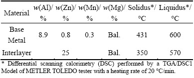
The cast AZ91 plates were cut into pieces in size of 25 mm �� 25 mm �� 7.5 mm and the cast interlayer (75% Mg and 25% Zn) plates were cut into foils in size of 35 mm �� 10 mm �� 2 mm.
Table 1 Chemical compositions and semisolid temperature ranges of base metal and interlayer
The interlayer foil was located between two AZ91 plates and they were put in a stainless steel open box. The fixture was placed on a small hot plate. The setup was placed on a trolley traveling with a speed of 4.6 mm/min. 5 g sulfur powder was poured into the tray to shield the process. Sulfur can form MgS on the surface of AZ91 plate, which is a protective layer to avoid oxidation. A bolt touching the stainless tray was put behind the pieces to fasten them together. The setup of experiment is shown in Fig. 1(a). As the elasticity of the stainless tray was very low and the interlayer was melted sooner than base metal (BM), BM did not experience any noticeable distortion.
A preheated drill-tip was introduced into the weld seam and tests were carried out at three different temperatures: 515, 530 and 540 ��C. At each temperature, five rotational speeds of 400, 800, 1200, 1600, and 2000 r/min were applied to welding the pieces. Further details about the welding procedure and tests can be found in Ref. [22]. The schematic presentation of the process is shown in Fig. 1(b).
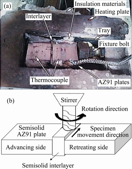
Fig. 1 Setup of semisolid welding (a) and schematic presentation of process (b)
It should be noted that an initial set of experiment was done in order to optimize process variables such as interlayer thickness, tool diameters, temperature range and rotational speed. Exceeding from the mentioned variables resulted in poor joints.
Polished transverse cross sections of welded coupons were etched with a reagent consisting of 60% ethylene glycol, 20% acetic acid, 1% HNO3 and 19% H2O (volume fraction) to reveal the macrostructure and microstructure. Light optical micrographs were taken with a high resolution OLAMPUS optical microscope. A scanning electron microscope (SEM) investigation was also carried out with a SEM VEGATESCAN. Vickers microhardness profiles were obtained using a 100 g load and a dwell time of 15 s with a Buhler 1600/6100 apparatus. Shear punch testing (SPT) was performed on a Hounsfield H10KS tensile test machine. The samples were 1 mm-thick, the diameters of punch and die were 2.99 mm and 3.01 mm, respectively. The output of punching was shear force-displacement and Eqs. (1) to (3) were used to calculate shear stress and normalized displacements.
t=F/(ptDavr) (1)
Davr=(D0+D1)/2 (2)
DN=D/t (3)
where t is the plate thickness, D0 and D1 are die and punch diameters. Ultimate shear stress (USS) and normalized displacement (ND) at the USS point were determined using a shear stress versus normalized displacement diagram based on the work by HOSSEINI et al [24].
3 Results
3.1 Joint macrostructure
The macrostructures of the samples welded with a rotational speed of 1600 r/min at different joining temperatures are presented in Fig. 2. The boundaries between the stir zone (SZ) and BM were mostly straight at 515 ��C. However, the pieces welded at the higher temperatures showed a wavier boundary and the BM close to the SZ was more broadly affected by stirring. As shown in Fig. 3(a), the BM was cracked when welded at 515 ��C with a rotational speed of 400 r/min. On the other hand, the high force led to the disintegration of the partially melted BM at 530 ��C and 400 r/min (Fig. 3(b)) and the disintegrated zone was fed by the slurry from SZ.
The stir zone width (SZW) is calculated as follows:
W=A/t (4)
where W is the stir zone width, A is the area of stir zone.
This equation can show an average for width of stir zone, which makes the weld size comparable. The variation of the SZW with rotational speed at different temperatures is presented in Fig. 4, which shows that SZW was wider than the thickness of the original interlayer for all rotational speeds. The lowest and highest values were 2.1 mm and 6.2 mm, respectively, which show the effect of parameters on the joint formation. SZW generally increased with increasing rotational speed. However, some expectations are presented like the stir zone widths of the samples welded with a rotational speed of 2000 r/min at 515 ��C and 530 ��C. SZW increased with increasing the joining temperature. In addition, it can be seen that the effect of rotational speed on SWZ increased with increasing the temperature (slope of the lines).
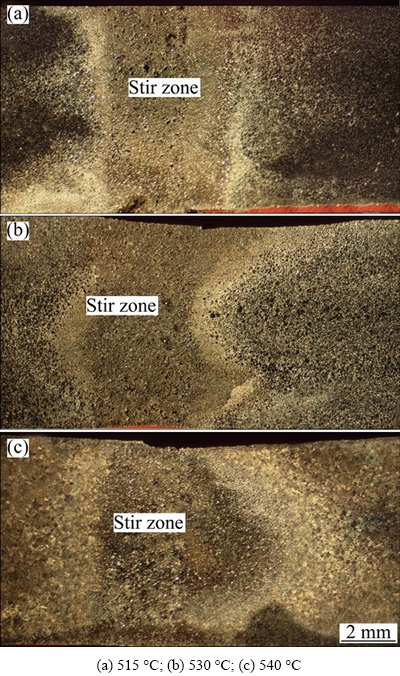
Fig. 2 Macrostructures of weld cross sections at different joining temperatures
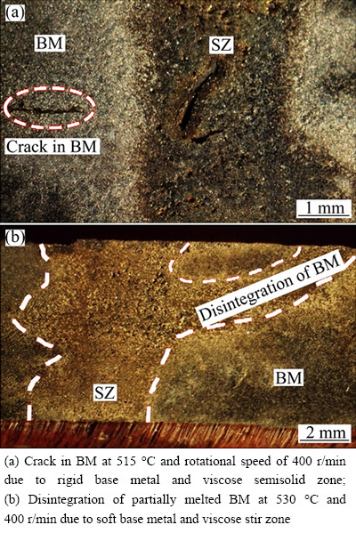
Fig. 3 Examples of defects formed in semisolid stir welding
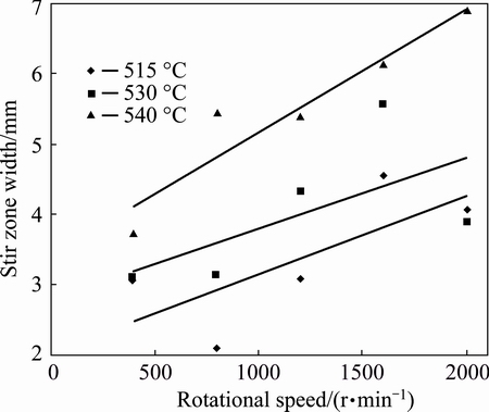
Fig. 4 Variation of stir zone width with rotational speed and joining temperature
3.2 Joint microstructure
The microstructure of the joint interface between SZ and BM is shown in Fig. 5(a). Oxide layers were completely disrupted at the interface of BM and interlayer, which illustrates a sound bond. By etching, three distinctive zones were revealed (Fig. 5(b)): stir zone (SZ), compacted zone (CZ), and diffusional- mechanical affected zone (DMAZ). SZ contains sheared dendrite and eutectic. CZ shows compacted grain structure with less eutectic content than that of the SZ. DMAZ shows globular structure with eutectic phase between and inside the globules.
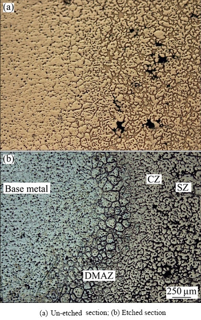
Fig. 5 Microstructures of joint interface region
Typical microstructures of the SZ at different joining temperatures and a rotational speed of 1600 r/min are shown in Fig. 6. The SZ has primary ��-Mg rosette shape globules, eutectic and cavities. The eutectic phase can be seen between and in the primary ��-Mg globules. As may be seen, sound microstructure were achieved at 530 ��C.
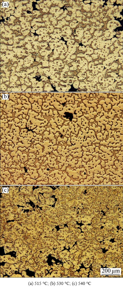
Fig. 6 Microstructures of stir zone consisting of primary ��-Mg (bright regions), eutectic (gray regions) and cavities (black areas) at 1600 r/min and different joining temperatures
Figures 7(a) and (b) show the variation of cavity area fraction and maximum cavity diameter (MCD) with rotational speed at different temperatures. The lowest cavity area fractions were achieved when temperature was 530 ��C, which was around 2% (same as cavity content of base metal). Intermediate rotational speed, obviously, showed lower cavity area fractions. The same observation was also seen in MCD, that intermediate rotational speeds and temperature resulted in lower values.
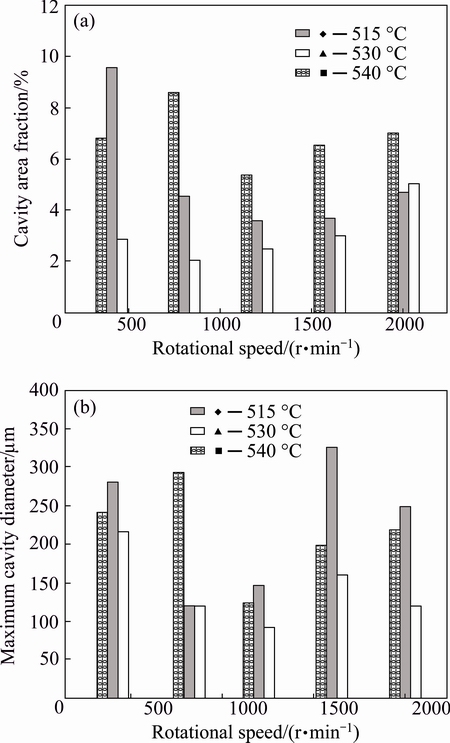
Fig. 7 Variation of cavity area fraction and maximum cavity diameter with joining temperature and rotational speed
The microstructure of DMAZ is illustrated in Fig. 8. Some secondary phases are presented in the globules, which are characteristics of semisolid metal, called ��liquid entrapped pools��. DMAZ, originally, was formed in the BM, as mentioned above. The elemental line scan, shown Zn and Al content, is also shown in Fig. 8. In the liquid entrapped pools, the ratio of aluminum to zinc content is higher than its ratio at the interlobular regions.
3.3 Mechanical properties
The hardness profiles of the samples welded at different temperatures and 1600 r/min are detailed in Fig. 9. The hardness of SZ is higher than that of BM at the lower temperatures. The nearest hardness of the SZ to that of the BM was obtained at 530 ��C. Hardness of the SZ decreased with increasing the temperature. On the other hand, the hardness of DMAZ increased with increasing the temperature. In addition, the size of zones having different hardness values with the BM increased with increasing the temperature. As may be seen, joint shows two different sides: advancing and retreating sides. Advancing side was more widely affected by stirring than that of retreating side in all welded samples.
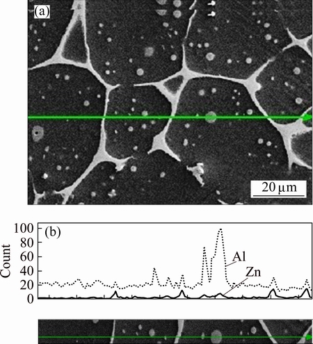
Fig. 8 SEM-EDX elemental line scan of globules at DMAZ
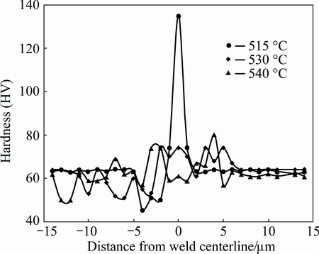
Fig. 9 Hardness profiles of weld cross sections
Schematic shear punch test diagram, ultimate shear stress and normalized displacement of different weldments are shown in Fig. 10. USS varied a little with the joining temperature for the intermediate rotational speeds, while ND was clearly higher at 530 ��C than that for the other joining temperatures. Very high and low rotational speeds showed lower USS and ND values at all temperatures.
4 Discussion
4.1 Interlayer and joint formation
Two possible alloying systems were considered as the interlayer: Mg-Zn and Mg-Al. LIU et al [25] reported that Mg-Zn-based intermetallic compounds were less brittle than Mg-Al, therefore, Mg-Zn was picked. The zinc content of 25% was chosen, because very low zinc content did not provide enough liquid fraction at joining temperatures, while very high zinc content can form detrimental intermetallic compounds in the final joint.
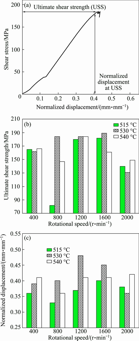
Fig. 10 Schematic shear punch test diagram (a), ultimate shear stress (USS) (b) and normalized displacement (ND) (c) obtained from shear punch test
Joints formed at all temperatures and rotational speeds. Two possible mechanisms assisted to disrupt the oxide layers and form the metallurgical bond, which depend on the rotational speeds and temperature, as shown in Fig. 11. The detailed mechanisms were discussed in Ref. [23]; however, it can be explained as follows.
As at lower rotational speeds and temperatures, viscosity of semisolid metal in the SZ was high and the stirring could not break the skeleton structure to turn it into the non-dendritic structure, higher torques were needed to stir the high viscose slurry to maintain a constant rate of the stirrer. Therefore, an intensive force was transferred to the interface through the skeleton and it disrupted the oxide layers. However, some defects formed due to the high force, where the cracks appeared in the BM. When temperature increased to 530 ��C, the BM became softer and the force disintegrated it.
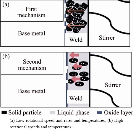
Fig. 11 Schematic presentation of joint formation mechanism
At higher rotational speeds and temperatures, the separated solid particles of the low viscose slurry were formed and second mechanism became more active. The separated solid particles crushed with the wall of BM due to the centrifugal force produced by the stirrer and disrupted the thick oxide layers. SHI et al [26] also proposed the same mechanism when a semisolid metal was used as a brazing filler metal. The comparison between the SZW and original interlayer thickness can be representation of dilution of BM in the SZ. At higher temperatures, the dilution increases due to softer BM and interlayer. Higher rotational speeds, in most cases, blended the BM and interlayer more severely. Some exception can be seen in Fig. 4, where the SZW decreased at the rotational speed of 2000 r/min. Very high rotational speed decreased the viscosity extremely and less viscose semisolid cannot affect the rigid BM at 515 ��C and 530 ��C significantly.
Both above mentioned mechanisms had their own effect on the joint formation at this variable range. Viscosity range is in the intermediate range due to the medium rotational speeds and temperatures, so heating the separated particles as well as force transformation in some solid particles were the responsible of joint formation. However, it should be noted that further viscosity and force measurements are needed for better understanding of the process. It can be concluded that the intermediate ranges of rotational speeds and temperatures provided the best joint formation mechanism, which is the combinations of both above mentioned ones.
4.2 Characteristics of joint
The formed microstructure showed a sound joint, where the gradient change from the BM to the SZ was observed. Three mentioned zones show different microstructures and they formed with different mechanisms. SZ formed due to the stirring and mixing the BM with the interlayer. CZ formed when centrifugal force detached the globules and attached them to the CZ. DMAZ shows a globular structure that formed by diffusion of liquid from the weld zone and mechanical deformation due to stirring the tool [22]. Figure 8 illustrates that the origin of entrapped pool was from the BM due to the high Al contents, while interlobular regions showed less Al contents due to the mixing of liquids from the SZ in DMAZ.
Two distinctive sides of welding were observed in DMAZ considering hardness profiles: advancing side and retreating side. The advancing side was formed because the opposite direction of stirrer velocity vector with piece velocity vector produced a higher crushing force than the other side (the retreating side). As shown in Fig. 3(b), the slurry penetrated into BM in the advancing side due to higher slurry crushing force at this side (400 r/min and 530 ��C).
4.3 Cavity formation mechanisms
Although the microstructure of SZ consists of cavities, intermetallic phase (eutectic structure) and primary ��-Mg, minimum cavity fraction is the key to achieve the sound SZ microstructure. So, based on the joint formation mechanisms, cavity formation in the SZ can be discussed as follows.
At a rotational speed of 400 r/min and 515 ��C, the cavities formed through solidification shrinkage were not fed by the channels existing in the solid network. It also caused the formation of larger cavity than that formed at the intermediate rotational speeds and 530 ��C. It is due to the skeleton solid structure resulting high viscose slurries. In the dendritic structure, it has been reported that attaching dendrite tips at dendrite coherency points also resulted higher pore formation and changing the feeding mechanisms in the solidification. The same mechanism was also expected here, where the dendritic structure was not demolished and temperature and rotational speeds were quite low [24].
After the disruption of solid network at higher rotational speeds (800 to 1600 r/min) and higher joining temperature, the situation for easy feeding was enhanced and the amount of cavities was reduced. At this set of variables, the balance between viscosity and liquid fraction was optimum and liquid ran into the cavities due to the separated solid particles. So, the minimum cavity area fraction was resulted.
The cavity content increased when the rotational speed or temperature increased due to decreasing the viscosity, which led to the entering more air into the slurry. In this situation, large cavities were formed at the higher temperatures or rotational speeds due to the attaching the small cavities to each other. In addition, slurries with higher content of liquid phase were extracted out of the joint. The main reason is the tool shape design. So, high liquid fraction was also not proper from the view of cavity formation.
4.4 Mechanical properties of joint
Hardness profile, at different joining temperatures, indicated that the BM was more affected with increasing the temperature. The lowest temperature showed quite high SZ hardness due to the low dilution of the BM and formation of brittle eutectic phases. In contrast, very high dilution resulting from the highest temperature led to the soft SZ, while liquid diffusion to the DMAZ formed hard brittle phases in this zone at 540 ��C. Consequently, the intermediate temperature dedicated the best hardness profile with consistent hardness through the joint.
At the intermediate rotational speeds and a joining temperature of 530 ��C, the maximum USS and ND were achieved due to the lowest MCD and cavity area fraction. While very big porosity or/and high cavity area fractions, at other cases, decreased the mechanical properties. Proper dilution of the BM in the SZ, also, brought adequate amount of eutectic, which strengthened the joint.
A practical formula was suggested in Ref. [22] to convert ultimate shear strength to ultimate tensile strength for this alloy as follows:
��T=1.015��S (5)
where ��T is the ultimate tensile strength, ��S is the ultimate shear strength. So, considering the ��S of 188 MPa for the best joint (1600 r/min and 530 ��C), the ��T for this weld is 191 MPa. The ��T for cast AZ91 is 207 MPa, consequently maximum joint efficiency (��T of joint/��T of base metal) is 92%.
5 Conclusions
Investigation of semisolid stir welded AZ91 pieces using 2 mm-thick Mg-25%Zn interlayer showed the vital role of joining temperature and rotational speed on the joint properties. A slight fluctuation of joining temperature, in which both BM and interlayer were in their semisolid state, affected the macrostructure, microstructure, and mechanical properties. The best mechanical properties of joint were obtained at 530 ��C. The rotational speeds from 800 to 1600 r/min were proper to meet desirable properties, while very high and low rotational speeds did not produce appropriate joint. Ultimate shear strength of the joint, obtained by shear punch test, was around 91% that of the BM due to the lowest cavity area fraction and proper joint size. In addition, the welded coupons joined at 530 ��C indicated the most uniform microhardness profiles. Disruption of oxide layers from the interfaces of interlayer and BM was the most important point to achieve an appropriate interface in this study.
Acknowledgments
The authors would like to thank Professor Leif KARLSSON (University West) for his valuable comments and Mr. Morteza MANSOORI (Sharif University of Technology) for his technical assistance. The author are also thankful from Innovatum (, Sweden) for the financial supporting the researcher in this paper.
References
[1] MENDEZ P, RICE C, BROWN S. Joining using semisolid metals [J]. Welding Journal 2002, 81(9): 181-187.
[2] SHALCHI A B, AASHURI H, KOKABI A H, ABBASI G M, MOLA J. Joining metals by combining mechanical stirring and thermomechanical treatment to form a globular weld structure [J]. Solid State Phenomena. 2006, 116: 397-401.
[3] NARIMANNEZHAD A, AASHURI H, KOKABI A, KHOSRAVANI A. Microstructural evolution and mechanical properties of semisolid stir welded zinc AG40A die cast alloy [J]. Journal of Materials Processing Technology. 2009, 209(8): 4112-4121.
[4] ALVANI S, AASHURI H, KOKABI A, BEYGI R. Semisolid joining of aluminum A356 alloy by partial remelting and mechanical stirring [J]. Transactions of Nonferrous Metals Society of China, 2010, 20(9): 1792-1798.
[5] XU H B, LUO Q X, LI C T, DU C H. Semi-solid stirring brazing of SiCp/A356 composites and aluminum alloy in air [J]. Advanced Materials Research. 2011, 189: 3521-3524.
[6] XU H B, ZENG Y L, DOU B, ZHANG C J, DING X Y. The microstructure of joint brazed by semisolid stirring brazing at high welding speed [J]. Advanced Materials Research, 2012, 528: 219-222.
[7] XU H B, LUO Q X, HE J Y, ZHOU B F, ZENG Y L, DU C H. Study of brazeability of SiCp/A356 composites and aluminum alloy using semisolid metal with high solid fraction by stirring [J]. Advanced Materials Research, 2011, 239: 663-666.
[8] XU H, XING Q, ZENG Y, LUO Y, DU C. Semisolid stirring brazing of SiCp/A356 composites with Zn27Al filler metal in air [J]. Science and Technology of Welding and Joining, 2011, 16(6): 483-487.
[9] XU H, LUO Q, ZHOU B, ZENG Y, DU C. The effect of stirring rate on semisolid stirring brazing of SiCp/A356 composites in air [J]. Materials & Design. 2012, 34: 452-458.
[10] XU H, ZHOU B, DU C, LUO Q, CHEN H. Microstructure and properties of joint interface of semisolid stirring brazing of composites [J]. Journal of Materials Science & Technology, 2012, 28(12): 1163-1168.
[11] FERASAT K, AASHURI H, KOKABI A H, NIKZAD S, SHAFIZADEH M. Characterization of newly developed semisolid stir joining method for cast cu base alloy (Cu-Al-Si-Fe) and effect of stirrer type on uniformity of microstructure [J]. Metallurgical and Materials Transactions A, 2015, 46(2): 762-770.
[12] FERASAT K, AASHURI H, KOKABI A H, SHAFIZADEH M, NIKZAD S. The effect of temperature and rotational speed on structure and mechanical properties of cast cu base alloy (Cu-Al-Si-Fe) welded by semisolid stir joining method [J]. Metallurgical and Materials Transactions A, 2015, 46(12): 5782-5788.
[13] SUBRAVEL V, PADMANABAN G, BALASUBRAMANIAN V. Effect of welding speed on microstructural characteristics and tensile properties of GTA welded AZ31B magnesium alloy [J]. Transactions of Nonferrous Metals Society of China, 2014, 24: 2776-2784.
[14] ZHANG Y, WU G H, LIU W C, ZHANG L, SONG P, DING W J. Effects of processing parameters on microstructure of semi-solid slurry of AZ91D magnesium alloy prepared by gas bubbling [J]. Transactions of Nonferrous Metals Society of China, 2015, 25: 2181-2187.
[15] HU M L, WANG Q D, JI Z S, XU H Y, XIN M D, MA G R. Wear behavior of Mg-10Y-4Gd-1.5Zn-0.4Zr alloy [J]. Transactions of Nonferrous Metals Society of China. 2016, 26: 406-413.
[16] CUI Z Q, SHI H X, WANG W X, XU B S. Laser surface melting AZ31B magnesium alloy with liquid nitrogen-assisted cooling [J]. Transactions of Nonferrous Metals Society of China, 2015, 25: 1446-1453.
[17] MA L, QIAO P, LONG W, HE D, LI X. Interface characteristics and mechanical properties of the induction brazed joint of magnesium alloy AZ31B with an Al-based filler metal [J]. Materials & Design, 2012, 37: 465-469.
[18] CAO X, JAHAZI M, IMMARIGEON J P, WALLACE W. A review of laser welding techniques for magnesium alloys [J]. Journal of Materials Processing Technology, 2006, 171: 188-204.
[19] SHEN J, YOU G, LONG S, PAN F. Abnormal macropore formation during double-sided gas tungsten arc welding of magnesium AZ91D alloy [J]. Materials Characterization. 2008, 59(8): 1059-1065.
[20] WAHBA M, MIZUTANI M, KAWAHITO Y, KATAYAMA S. Laser welding of die-cast AZ91D magnesium alloy [J]. Materials and Design, 2012, 33: 569-576.
[21] SUN D X, SUN D Q, GU X Y, XUAN Z Z. Hot cracking of metal inert gas arc welded magnesium alloy AZ91D [J]. ISIJ International, 2009, 49(2): 270-274.
[22] HOSSEINI V A, AASHURI H, KOKABI A H. Characterization of newly developed semisolid stir welding method for AZ91 magnesium alloy by using Mg-25%Zn interlayer [J]. Materials Science and Engineering A, 2013, 565: 165-171.
[23] HOSSEINI V, AASHURI H, KOKABI A. Mechanisms of joint formation throughout semisolid stir welding of AZ91 magnesium alloy [J]. Transactions of Nonferrous Metals Society of China, 2013, 23(9): 2585-2590.
[24] HOSSEINI V A, SHABESTARI S G, GHOLIZADEH R. Study on the effect of cooling rate on the solidification parameters, microstructure, and mechanical properties of LM13 alloy using cooling curve thermal analysis technique [J]. Materials & Design, 2013, 50: 7-14.
[25] LIU L, TAN J, LIU X. Reactive brazing of Al alloy to Mg alloy using zinc-based brazing alloy [J]. Materials Letters, 2007, 61(11): 2373-2377.
[26] SHI L, YAN J, HAN Y, PENG B. Behaviors of oxide layer at interface between semi-solid filler metal and aluminum matrix composites during vibration [J]. Journal of Materials Science & Technology, 2011, 27(8): 746-752.
���Ӳ������̬���躸��Mg-9Al-1Znþ�Ͻ��Ӱ��
V. A. HOSSEINI1, H. AASHURI2, A. H. KOKABI2
1. Department of Engineering Science, University West, SE-461 86 , Sweden;
2. Materials Science and Engineering Department, Sharif University of Technology, Azadi Ave., Tehran, Iran
ժ Ҫ���о������¶Ⱥ�ת�ٶ��̬���躸��AZ91�Ͻ��Ӱ�졣��Mg-25%Zn�м���������AZ91����м䣬Ȼ����������м����������̬״̬���ڲ�ͬ�¶Ⱥ�ת��������ͷ�Ժ�����н��衣���ù�ѧ������ɨ����������о����ϵ�����֯���ն��γɺ�ƫ��������Ӳ�ȷֲ�ͼ�ͳ��ʵ��Խ�ͷ�ĺ��������;����Խ���������������������¶�Ϊ530 ��C��ת��Ϊ1600 r/minʱ���ɵõ���͵Ŀն�����(2.1%)����ߵĿ���ǿ��(188 MPa)���¶Ⱥ�ת�ٹ���̫�Ͷ�ʹ���������Ϳ���ǿ�Ƚ��͡���ˣ����е��¶Ⱥ�ת���£����̬���躸�ӿ��Ի�þ��ȵĽ�ͷ��������������ѧ���ܡ�
�ؼ��ʣ�Mg-Al-Zn�Ͻ𣻻�е���裻���̬���躸��
(Edited by Yun-bin HE)
Corresponding author: V. A. HOSSEINI; Tel: +46-76-41-40-928; Fax: +46-520-22-30-99; E-mail: vahid.hosseini@hv.se
DOI: 10.1016/S1003-6326(16)64384-4
Abstract: Semisolid stir welding of AZ91 was investigated with focus on the joining temperature and rotational speed. An Mg-25%Zn interlayer was located between two AZ91 pieces and the system was heated up to the semisolid state of base metal and interlayer. The weld seam was stirred using a drill-tip at different joining temperatures and rotational speeds. Optical and scanning electron microscopes were employed to study microstructure, cavity formation, and segregation. Hardness profile and shear punch test were also employed to rank the welds based on their quality and homogeneity. Results showed that the lowest cavity content (2.1%) with the maximum ultimate shear strength (about 188 MPa) was obtained in weld with the joining temperature of 530 ��C and the rotational speed of 1600 r/min. Low quality welds and a reduction of ultimate shear strength were observed at very high or low rotational speeds and joining temperatures. The process, in conclusion, produced close mechanical properties to those of the base metal and homogenous quality throughout the joint, when the intermediate temperature and rotational speeds were employed.
