
J. Cent. South Univ. Technol. (2011) 18: 718-725
DOI: 10.1007/s11771-011-0753-z![]()
Optimal rotor wear design in hypotrochoidal gear pump using genetic algorithm
KWON Soon-man, KIM Chang-Hyun, SHIN Joong-ho
Department of Mechanical Design and Manufacturing Engineering, Changwon National University,
Changwon 641-773, Korea
? Central South University Press and Springer-Verlag Berlin Heidelberg 2011
Abstract:
The wear rate between the rotors of a hypotrochoidal gear pump is characterized. Using the knowledge of shape design on the rotors, the contact stresses without hydrodynamic effect between the rotor teeth were evaluated through the calculation of the Hertzian contact stress. Based on the above results and the sliding velocity between the rotors, a genetic algorithm (GA) was used as an optimization technique for minimizing the wear rate proportional factor (WRPF). The result shows that the wear rate or the WRPF can be reduced considerably, e.g. approximately 12.8%, throughout the optimization using GA.
Key words:
1 Introduction
Most important studies [1-7] on gerotor (generated rotor) pump are focused on commercially available gerotor pump using the equidistant shortened epitrochoid curve to the authors�� best knowledge. To improve the carryover phenomenon of the traditional gerotor design, recently HWANG and HSIEH [8] presented a geometry design procedure based upon the theories of envelope and conjugate surfaces for the hypotrochoidal gear pump using the equidistant extended hypotrochoid curve. They also presented the non-undercut conditions of the outer-rotor using the theory of gearing [9]. However, the procedure for obtaining the non-undercut conditions of Ref.[8] is somewhat complicated with the added disadvantages that equations must be solved numerically.
Also, a disadvantage in the design of hypotrochoidal gear pumps as that in a traditional gerotor pump is the lack of parts that can be adjusted to compensate for wear in the rotor set, and as a consequence, this causes sharp reduction of volumetric efficiency. Therefore, when the rotors become worn, they must simply be replaced [10]. The main difficulty in calculating the contact stress is to determine the force that is transmitted through each contact point. Since there are many contact points, at any instant, the problem is statically indeterminate, and it is necessary to consider the tooth deformation at the contact points.
To investigate the wear characteristic of the rotors, in this work, the method on outer-rotor profile design of a hypotrochoidal gear pump is firstly revisited following the result of KWON et al [11]. Next, the radius of curvature of the outer-rotor is derived with the relationships of the trochoid ratio and the inner-rotor tooth size ratio. Then, by examining the minimum radius of curvature of the outer-rotor on the convex section following the methodology of YE et al [12], an explicit formula for the limit dimensions to avoid self- intersection or undercut is proposed.
Based on the above knowledge of shape design on the rotors, the wear characteristics under quasi-static and dry (or without hydrodynamic effect) contact conditions are presented. Then, a genetic algorithm (GA) is used as the optimization technique for minimizing the wear rate proportional factor (WRPF).
2 Outer-rotor profile
2.1 Profile equation
The following is a brief summary of the outer-rotor geometry, which is described in more details in Refs.[11, 13].
Figure 1 shows a schematic diagram of the hypotrochoidal gear pump. The number of teeth of the outer-rotor is always one more than that of the inner-rotor, i.e. they have (N+1) and N teeth, respectively. Any shape can be chosen for the inner-rotor teeth, and the outer-rotor is then generated conjugated to the inner-rotor. It is described here that only the inner-rotor has N arcs of circle in the placement of R=![]() (i=1, 2, 3, ��, N) from its center with the radius of Rr. The center distance or eccentricity between the rotors is E. It can be regarded as a mechanism of three-links and three-joints: the frame corresponding to E=
(i=1, 2, 3, ��, N) from its center with the radius of Rr. The center distance or eccentricity between the rotors is E. It can be regarded as a mechanism of three-links and three-joints: the frame corresponding to E=![]() as link 1, the outer-rotor as link 2, and the inner-rotor as link 3.
as link 1, the outer-rotor as link 2, and the inner-rotor as link 3.
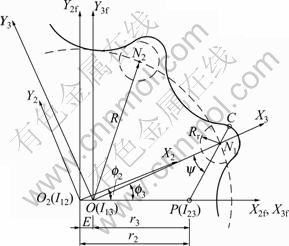
Fig.1 Schematic diagram for outer-rotor profile derivation
The inner-rotor turns around its center O3 with the angular velocity of ��3, the outer-rotor turns around O2 with ��2 in the same orientation of ��3, and the angular velocity ratio is (N+1)?N. From the information of the angular velocity ratio and r2-r3=E, the relations of r2= ![]() E(N+1) and
E(N+1) and ![]() can be derived. Here, I23 means the pitch point.
can be derived. Here, I23 means the pitch point.
If we define f by the generated parameter of the output motion, which is the counterclockwise rotation of the inner-rotor relative to the outer-rotor in this work, then the counterclockwise generated parameters f2 and f3 of the outer and inner-rotors are given by
![]() (1)
(1)
To derive the profile equations of the outer-rotor, four coordinate systems corresponding to the rotor set should be defined, as shown in Fig.1: two stationary reference systems S2f and S3f, and two mobile reference systems S2 and S3. For the homogeneous coordinate transformation from the contact point of 3C in S3-reference system to that of 2fC in S2f-reference system, the following matrix equation is defined:
![]() (2)
(2)
where the matrix Mi,j describes the transformation from the Sj-system to Si-system, and ��2 is the rotation angle of the outer-rotor and
 (3)
(3)
where the parameter of ��=R/r3 is referred to as the trochoid ratio. It is noted that the designer of the gerotor pumps should adopt the curtate hypotrochoid curves (i.e. ��>1) to avoid the self-intersection phenomenon.
2.2 Non-undercut condition
During the design stage of the hypotrochoidal gear pump, the size (Rr) and the placement (R) of the cylindrical inner-rotor teeth are those of important dimensions. If Rr is larger than a maximum value or R is less than a minimum value, then the enveloped tooth profile of the outer-rotor will self-intersect (see Fig.2). The tooth profile of the outer-rotor will therefore be undercut. This will produce backlash between the rotors during running, and will become a potential problem, e.g. a decrease in volumetric efficiency. It is, therefore, important to calculate the limit dimensions to avoid undercutting on the outer-rotor when designing the hypotrochoidal gear pump. It is also well known that the wear rate can be reduced by increasing the radius of curvature of the lobes. The radius of curvature is a function of the size and the placement of the inner-rotor teeth which generate the lobe shape.
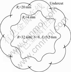
Fig.2 Design example for showing self-intersection
Following the result and procedure of Refs.[11-12], the radius of curvature of the outer-rotor can be obtained as
![]() (4)
(4)
where (x, y) are the parametric coordinates of the standard hypotrochoid curve, (x��, y��) and (x��, y��) are the first and the second derivatives of (x, y) with respect to the parameter of f, respectively. If ��>0 in Eq.(4), then the location of the center of curvature is to the right of the path (i.e. convex profile).
The resulting expression of Eq.(4) is found in the form:
![]() (5)
(5)
where ��(=Rr/R) is the inner-rotor tooth size ratio.
To demonstrate the self-intersection phenomenon, two outer-rotors are depicted simultaneously in Fig.2. The same design parameters (R=32 mm, N=8, E=3.5 mm) have been used in Fig.2, with the exception of Rr (equal to 4 mm in the smaller rotor and 20 mm in the larger rotor).
Figure 3 shows the relationship between the radius of curvature �� of the tooth profile and the generated parameter f3. From Fig.3, we can observe that the radius Rr of the inner-rotor tooth increases, then �� decreases. If Rr is larger than a limit value, the minimum radius of curvature on the convex section, ��min, will be negative and the tooth profile of the outer-rotor will be intersecting. This will produce backlash between the outer-rotor and inner-rotor during running. To avoid this self-intersecting, the point with zero radius of curvature must be avoided, i.e. the minimum value of �� of the tooth profile on the convex section should not be less than zero.
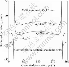
Fig.3 Radius of curvature for outer-rotor lobe profile
In order to calculate ��min on the convex section, equation (5) is differentiated with respect to f3 and the result is set to zero. After rearranging, the following result in an explicit formula for calculating the maximum value of ��max of the inner-rotor tooth size ratio to avoid undercutting on the outer-rotor can be obtained:
![]() (6)
(6)
If Rr has been determined beforehand, then the minimum distance, Rmin, can be calculated by the following explicit formula derived from Eq.(6):
![]() (7)
(7)
Using Eqs.(6) and (7), it is very easy to calculate the limit dimensions. For example, if the design parameters are given by R=32 mm, N=8, and E=3.5 mm as shown in Figs.2 and 3, the maximum inner-rotor tooth radius to avoid undercutting is (Rr)max=13.04 mm.
3 Contact stress
3.1 Contact force between rotors
Figure 4 shows a specific unit of the inner-rotor running angle of ��3=22.5�� (��2=20��) with the following geometric parameters: R=32.0 mm, Rr=4.0 mm, N=8 and eccentricity E=3.5 mm.
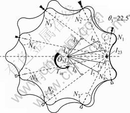
Fig.4 Distribution of contact forces for specific unit
Since there are several contact points, the problem of calculating the contact forces (concurrent force system at the pitch point I23) is statically indeterminate.
The method used here to find the contact forces is as follows. It is assumed that the bearings of both rotors are stiff compared with the stiffness ke of the teeth. Thus, when a couple is applied to the inner-rotor, it will rotate a small amount ���� about its axis, until the tooth deformations ��i (=li����) are sufficiently large to provide forces whose combined moments about O3 are equal to Tin (see Fig.5). At any instant, about half of the teeth will have contact forces which contribute to the moment Tin; while at the remaining teeth, a small separation opens up, and there is in fact no contact. Black arrows shown in Fig.4 represent the magnitude range of the contact force for the reference position, while the white arrows represent no force.
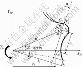
Fig.5 Derivation of contact force at i-th inner-rotor
If the input torque Tin about O3 is given (Fig.5), the contact force to the inner-rotor Fi at any tooth Ni can be found from the condition of moment equilibrium with the aid of the Palmgren relation [14] ![]() where n=10/9) as
where n=10/9) as
 (8)
(8)
where the value of li can be calculated in the form:
![]() (9)
(9)
and ��i is the active zone discerning parameter. It is 1 for 0<![]() <�� but 0 for ��
<�� but 0 for ��![]() ��2��. The geometric definitions of mi and
��2��. The geometric definitions of mi and ![]() are
are ![]() and 2��(i-1)/N+ ��3, respectively.
and 2��(i-1)/N+ ��3, respectively.
If the normal forces at contact points are known, it is possible to evaluate the Hertzian contact stress, pH, at the contact point of the i-th inner-rotor as
![]() (10)
(10)
where H is the rotor thickness, E* is the reduced modulus of elasticity, and R*=(1/��i+1/Rr)-1, is the composite radius of curvature. In this relation, the value of the radius of curvature ��i is determined using the Euler-Savary equation [15] in the form:
![]() (11)
(11)
where ![]() can be found as
can be found as
![]() (12)
(12)
Figure 6 demonstrates the results of Hertzian contact stresses for the case when the input torque Tin=5.0 N��m with the same geometric parameters of Fig.4. Material properties are E=210 GPa and ![]() 0.29 for all the rotors, and the rotor thickness is H=9.25 mm.
0.29 for all the rotors, and the rotor thickness is H=9.25 mm.
3.2 FE analysis
The simulation work is now taken under study for the same geometric and input parameters with Section 3.1. The specific volume (or the theoretical displacement) is evaluated to be 12.62 cm3/rev and determined using the following formula:
![]() (13)
(13)
where ��A is equal to the difference of the maximum chamber area and the minimum chamber area. The manufacturing, clearance and thermal effects are not taken into account in this preliminary approach. The profiles of the rotors have to be defined very accurately in order to obtain a correct geometry of the assembled rotor set. Initial penetration has to be avoided because a virtual interference would appear, producing unreal results. For this approach, the commercial FEA package of ANSYS? is used.
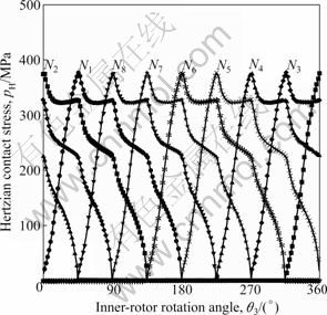
Fig.6 Hertzian contact stresses at contact points
Figure 7 shows the FE mesh of the assembled rotor set. The elements have been more refined at the contact points. A small rotation of ���� is given to the inner-rotor using MPC184 element and the contact stress at the contact point is calculated by the penalty of the penetration caused in each tooth. The analysis has been carried out in a quasi-static mode without taking into account of the dynamic components in the deformation equations.
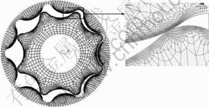
Fig.7 FE mesh result
Figure 8 shows an example of the analysis, and the maximum result of von-Mises stress is 131.426 MPa at the mesh point of the 2nd inner-rotor tooth while 135.33 MPa via Eq.(10). The input torque of 5.0 N��m is applied on the center of the inner-rotor at the rotation position of ��3=22.5��. Also the selected material properties are E=210 GPa and ![]() 0.29 for all the rotors.
0.29 for all the rotors.
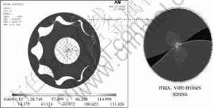
Fig.8 Post-processing result (von-Mises stress/MPa)
4 Optimization of wear rate
4.1 Wear rate proportional factor (WRPF)
Based on the experimental data of various unlubricated (dry) material pairs with the vast majority being metallic, it is possible to write the laws of adhesive wear as follows. The amount of wear is generally proportional to the applied load and the sliding distance and generally inversely proportional to the hardness of the surface worn away. For a designer who is interested in the rate of wear depth, the wear rate is proportional to the pHvs factor (here vs is the sliding velocity) or the life of an interface is inversely proportional to the pHvs factor. The factor of pHvs/��3 in this work is referred to as the wear rate proportional factor (WRPF).
The sliding velocity at the meshing point of Ci between the i-th inner-rotor and the outer-rotor teeth can be found of the form:
![]() (14)
(14)
where ��3 and ��2 are the angular velocities of the inner and outer-rotors, respectively.
The WRPF (Fw) of the tooth contact point at the i-th inner-rotor (Ni) with the rotation of the inner-rotor is shown in Fig.9. Only five results out of total eight for graphical brevity are presented.
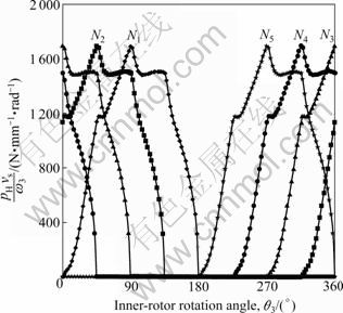
Fig.9 WRPF with variation of inner-rotor rotation angle
It is revealed that the sliding velocity (not described graphically in this work) arrives at the maximum value when the inner-rotor lies on negative x3f-axis (e.g., ��3=�� for Ni tooth) or the minimum chamber volume appears. However, the maximum wear position is expected at a shift rotational position before arriving at the maximum sliding position (in this case ��3�֦�/2 for Ni tooth). This WRPF on the milestone work will be generally used as a relative wear performance index for the selection of the rotor set material pairs and the geometric parameters.
4.2 WRPF optimization using GA
GA is a search technique aiming at global optimization which works starting from an initial population representing possible solutions of the problem. In this work, a simple GA based on an elitist strategy by preserving the core of the best solutions during the evolutionary process is presented.
A numerical test is performed to find out the optimum rotor geometry for minimum WRPF under guaranteeing identical Vth of the previous example (refer to Section 3). The obtained results are discussed and finally some qualitative remarks are made.
4.2.1 Problem statement
Since the present optimization seeks to minimize the WRPF at the rotor set, the system searches for the optimum inner-rotor geometries within the constant Vth using GA, that is,
 (15)
(15)
From Eq.(15), the following three design constraint functions are considered which constitute a penalty function to be described:
![]() (16)
(16)
![]() (17)
(17)
![]() (18)
(18)
The parameters and searching ranges of design variables used in the GA for the case investigated here are presented in Tables 1 and 2. In Table 1, Np, Ng, Pc and Pm are, respectively, the population size, the number of generations, the crossover probability and the mutation probability. And the upper and lower bounds of design variables in Table 2 are determined according to the procedure not to deviate seriously the previous- mentioned example geometries.
Table 1 Designing of genetic parameters
![]()
Table 2 Searching ranges for GA
![]()
4.2.2 Fitness function
After identifying the design variables and search domain that represents the population phenotype, different solutions are represented by an appropriate code format called the genotype. Here, a decimal code is used for each design variable. The fitness is related to the objective function of the problem which is defined as
![]() (19)
(19)
where 1 700 (an arbitrary constant) is considered to increase with the decrease of WRPF (Fw) values for the
fitness function. ![]() of Eq.(19) represents a
of Eq.(19) represents a
penalty function, and gk is constraint or one of the relations introduced in Eqs.(16)-(18). And the weighted constant Bk of the penalty function is set to unity in this work.
The developed GA is based on four operators: selection, crossover, elimination/replacement and mutation supported by an elitist strategy that always preserves a core of the best individuals of the population. This elitist strategy performs at two stages: 1) in the choice of parents with a selection probability based on the fitness values, and 2) in the elimination of the worst individuals. Also, in the mutation process, new improvements are reached by introducing an adaptive scheme linked with the improvements of the fitness of the population.
Figure 10 represents the flow chart of the program and the main steps governing the evolution of the population.
4.2.3 Results and discussion
The best fitness evolution for the GA is shown in Fig.11. The solution process is converged after 220 generations.
First of all, Figs.12 and 13 show the contact forces and the Hertzian contact stresses between the first inner-rotor tooth and the meshing outer-rotor tooth with the rotation of the inner-rotor. The contact forces are slightly increased after optimization in Fig.12, due to either the decrease of eccentricity E or the decrease of li (referring to Eq.(9)).
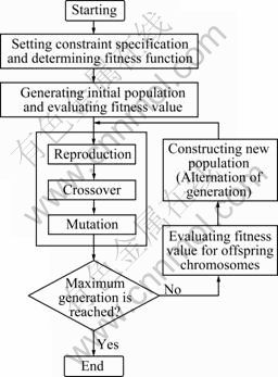
Fig.10 GA flow chart
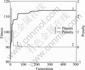
Fig.11 History of fitness and penalty function
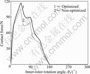
Fig.12 Contact force before and after optimization
On the whole, the Hertzian contact stress pH is decreased remarkably in Fig.13 after optimization. This is resulted from the increase of the composite radius of curvature R* and the rotor thickness H.
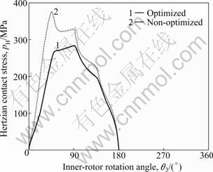
Fig.13 Hertzian contact stress before and after optimization
The normalized sliding velocities at the first inner- rotor tooth are depicted in Fig.14. It can be seen that the variations are slight after optimization.
However, the value of (Fw)max is considerably reduced as shown in Fig.15, approximately by 12.8% in this example, throughout the optimization using GA. This comes from the reduction of pH in the main but little variation of Vs as seen in Figs.13 and 14.
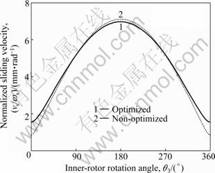
Fig.14 Sliding velocity before and after optimization
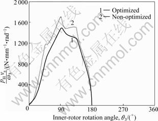
Fig.15 WRPF before and after optimization
The rotor set profiles before and after optimization are displayed in Fig.16 using the developed CAD program.
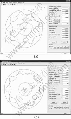
Fig.16 Assembled rotor set shape before and after optimization: (a) Non-optimized shape; (b) Optimized shape
5 Conclusions
The contact stresses without hydrodynamic effect obtained by the analytical method and the FE simulation gave an optimum exactness to take into consideration of the results and to continue this work. Also, using a genetic algorithm as the optimization technique for minimizing the wear rate, the wear rate could be reduced considerably.
[1] COLBOURNE J R. Reduction of the contact stress in internal gear pumps [J]. Transactions of the ASME: Journal of Engineering for Industry, 1976: 1296-1300.
[2] FABIANI M, MANCO S, NERVEGNA N, RUNDO M. Modeling and simulation of gerotor gearing in lubricating oil pumps [R]. SAE Transactions N 1999-01-0626, 1999: 989-1003.
[3] MANCO S, NERVEGNA N, RUNDO M. A contribution to the design of hydraulic lube pumps [J]. International Journal of Fluid Power, 2002, 3(1): 1-11.
[4] SAENKO V P, GORBATYUK R N. On gerotor hydraulic machine design [J]. Russian Engineering Research, 2004, 24(7): 8-14.
[5] RANGANATHAN G, RAJ T H S, RAM P V M. Wear characterization of small PM rotors and oil pump bearings [J]. Tribology, 2004, 37: 1-9.
[6] VECCHIATO D, DEMENEGO A, ARGRIS J, LITVIN F L. Geometry of a cycloidal pump [J]. Computer Methods in Applied Mechanics and Engineering, 2001, 190: 2309-2330.
[7] MIMMI G C, PENNACCHI P E. Non-undercutting conditions in internal gears [J]. Mechanism and Machine Theory, 2000, 35: 477-490.
[8] HWANG Y W, HSIEH C F. Geometry design using hypotrochoid and nonundercutting conditions for an internal cycloidal gear [J]. Transactions of the ASME: Journal of Mechanical Design, 2007, 129: 413-420.
[9] LITVIN F L, FUENTES A. Gear geometry and applied theory [M]. Cambridge, UK: Cambridge University Press, 2004: 1-266.
[10] COLBOURNE J R. The geometry of trochoid envelopes and their application in rotary pumps [J]. Mechanism and Machine Theory, 1974, 4: 421-435.
[11] KWON S M, KANG H S, SHIN J H. Rotor profile design in a hypogerotor pump [J]. Journal of Mechanical Science and Technology, 2009, 23: 3459-3470.
[12] YE Z, ZHANG W, HUANG Q, CHEN C. Simple explicit formulae for calculating limit dimensions to avoid undercutting in the rotor of a cycloid rotor pump [J]. Mechanism and Machine Theory, 2006, 41: 405-414.
[13] SHIN J H, KWON S M. On the lobe profile design in a cycloid reducer using instant velocity center [J]. Mechanism and Machine Theory, 2006, 41(5): 596-616.
[14] PALMGREN A. Les roulements, description, theories, applications [M]. SKF Compagnie d��Applications Mecaniques, 1967.
[15] SHIGLEY J E, UICKER Jr J J. Theory of machines and mechanisms [M]. New York: McGraw-Hill, 1980: 153-158.
(Edited by YANG Bing)
Foundation item: Research Financially supported by Changwon National University in 2010, Korea
Received date: 2010-06-29; Accepted date: 2010-11-30
Corresponding author: SHIN Joong-ho, Professor, PhD; Tel: +82-55-213-3621; E-mail: joongho@changwon.ac.kr
