
J. Cent. South Univ. (2016) 23: 544-554
DOI: 10.1007/s11771-016-3101-5

Tooth surface geometry optimization of spiral bevel and hypoid gears generated by duplex helical method with circular profile blade
ZHANG Yu(����)1, YAN Hong-zhi(�Ϻ�־)1, ZENG Tao(���)1, 2, ZENG Yi-yu(������)2
1. State Key Laboratory of High Performance Complex Manufacturing, College of Mechanical and Electrical Engineering, Central South University, Changsha 410012, China;
2. Changsha Haliang Kaishuai Precision Machinery Co. Ltd., Changsha 410100, China
 Central South University Press and Springer-Verlag Berlin Heidelberg 2016
Abstract:
In order to effectively improve meshing performance of spiral bevel and hypoid gears generated by the duplex helical method, the effects of straight lined and circular cutting edges profile on meshing and contact of spiral bevel and hypoid gears were investigated analytically. Firstly, a mathematical model of spiral bevel and hypoid gears with circular blade profile was established according to the cutting characteristics of the duplex helical method. Based on a hypoid gear drive, the tooth bearings and the functions of transmission errors of four design cases were analyzed respectively by the use of the tooth contact analysis (TCA), and the contact stresses of the four design cases were analyzed and compared using simulation software. Finally, the curvature radius of the circular profile blade was optimized. The results show that the contact stresses are availably reduced, and the areas of edge contact and severe contact stresses can be avoided by selecting appropriate circular blade profile. In addition, the convex and concave sides are separately modified by the use of different curvature radii of inside and outside blades, which can increase the flexibility of the duplex helical method.
Key words:
1 Introduction
There are two main methods of producing spiral bevel and hypoid gears generated by face milling in the automobile gear manufacturing industry today. One is the single indexing method referred to as the five-cut process or the fixed setting method, which is widely used in China, but has been eliminated by the developed western countries. The other is the continuous indexing method referred to as the duplex helical method or the completing process, which is generally used in the advanced western countries and has the characteristics of high efficiency and dry cutting. But at the same time, spiral bevel and hypoid gears generated by the duplex helical method need tooth surface geometry optimization (modification) in order to get good meshing quality.
In order to effectively improve contact and meshing performance of spiral bevel and hypoid gears drive, a set of carefully chosen modifications is usually applied to the teeth of one or both mating gears. In practice, modifications are usually introduced by using a head cutter with an optimized profile. Since many decades, numerous authors have carried out many studies about modification of spiral bevel and hypoid gears cut by face-milling [1-4] and face-hobbing [5-7] method with the parabolic, circular arc and other kinds of curves of the blades instead of the straight profile blades. KAWASAKI [8] introduced circular arc cutting edges for absorbing the alignment errors in the Klingelnberg cyclo-palloid system. SHIH [9] proposed two kinds of modifications, profile and lengthwise crownings implemented on the pinion using circular cutter edges and extend hypocycloidal motion for face-hobbed straight bevel gear using a hypocycloidal mechanism. SIMON [10-12] investigated the influence of tooth modifications induced by machine tool setting and head-cutter profile variations on tooth contact characteristics in face-hobbed spiral bevel gears. An analysis of the surface geometry of spiral bevel gears formed by a circular cutter with involute, straight, and hyperbolic profile was presented HUSTON and COY [13]. LITVIN et al [14-17], introduced parabolic and Top-Rem profile blade for avoiding areas of severe contact stress and edge contact. SIMON [18-19] presented optimal tooth modifications introduced into pinion tooth-surface by using a head-cutter with bicircular profile and with optimal diameter in order to improve load distribution and reduce the maximum tooth contact pressure and transmission errors.
However, evidently, the previous studies about modification of spiral bevel and hypoid gears cut by face-milling with the curve blade profiles are carried out for the five-cut process. Due to the different principles and machining characters between the five-cut process and the duplex helical method, how to improve meshing performance of spiral bevel and hypoid gears generated by the duplex helical method with the curve profile blades is a new research field. In this work, a mathematical model of hypoid gears generated by the duplex helical method with the circular profile blades was established and two types of cutting edge profiles for cutters were considered. One was a straight lined cutting edge and the other was a circular arc cutting edge. Using two types of the cutting edge profiles, the contact bearings and the functions of transmission errors were analyzed and the curvature radii of the circular profile blades were optimized.
2 Mathematical model of spiral bevel and hypoid gears generated by duplex helical method with circular profile blades
2.1 Mathematical model of gear tooth surface
In face milling, gear may be cut using either a generating method or a non-generating (formate) method. The mathematical model of gear generated by the duplex helical method is the same as that of gear generated by the five-cut process. In generating processes, the cutting tool represents one tooth of a generating gear while it rotates around the cutter head axis. The rotation of the cutter head center around the generating cradle axis represents the rotation of the generating gear, which is in mesh with the work gear. This in turn requires that the work gear rotates with the correct ratio between generating gear and work gear. The results of manufacturing simulation are the surfaces of gear and pinion teeth, described as the points and normal vectors of surface grids. In no-generating (formate) processes, the generating cradle axis is fixed, no generating roll is employed, so the profile shape of tooth on a workpiece is produced directly from the profile shape on the tool.
2.1.1 Part (a) of generating surface for gear circular profile head-cutter
The geometry of the circular profile blade for the gear head-cutter is represented in this section.Figures 1(a), (b) and (c) show illustration of the circular profile blade for the gear head-cutter, and the generating tool surfaces for the convex and concave sides, respectively. As shown in Fig. 1, the coordinate system S0{X0, Y0, Z0} is rigidly connected to the gear head-cutter;Z0 is the axis of the head-cutter; ��2 is the rotation angle; each side of the blade generates two sub-surfaces denoted as parts (a) and (b) of the generating surfaces; the segment of the circular arc (part (a)) with the curvature radius R2 (including the curvature radius of the concave side R2c and the convex side R2d) generates the working part of the gear tooth surface; the circular arc of radius ��2 generates the fillet of the gear tooth surface (part (b)); ��2 is the pressure angle (including the pressure angle of the concave side ��2c and the convex side ��2d) at the reference point M; s02 is the distance from the top of the blade to the reference point; Pw2 is the point width; r02 is the cutter mean radius; r2 is the cutter point radius (including the pressure angle of the concave side r2c and the convex side r2d); s2 and ��2 are the surface coordinates of the part (a); ��2 and ��2 are the surface coordinates of the part (b). Surface  of the head-cutter is represented by vector function
  as follows:
 (1)
(1)
The cutter point radius r2 is given by
 (2)
(2)
The unit normal to the gear generating surface  is represented by the equation:
 (3)
(3)
Equations (1) and (3) yield

 (4)
(4)
The upper and lower signs in Eqs. (1), (2) and (4) correspond to generation of the convex and concave sides of the gear tooth surface, respectively.
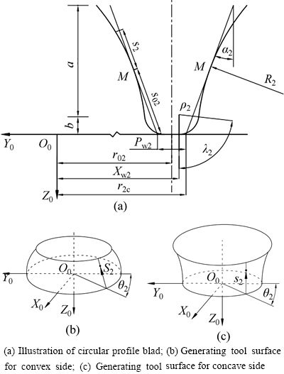
Fig. 1 Circular profile blade and generating revolution surfaces for gear head-cutter:
2.1.2 Part (b) of generating surface for gear circular profile head-cutter
In the coordinate system S0, surface  of the head-cutter is represented by vector function
  as follows:
 ,
,
 (5)
(5)
where
 (6)
(6)
According to Eq. (3), the unit normal vector of the gear generating surface is determined as
 (7)
(7)
The upper and lower signs in Eqs. (5), (6) and (7) correspond to generation of the convex and concave sides of the gear tooth surface, respectively.
2.1.3 Equations of gear tooth surface
Coordinate system Sm{Xm, Ym, Zm} is rigidly connected to the cutting machine (Fig. 2). The top, bottom and upper right of Fig. 2 are the machine front view, the machine bottom view and the side view (the projection of head cutter), respectively. The cradle is rotated about the Ym-axis; the p2-axis is projection of the gear axis in the XmOmYm-plane. The points M, P and O0 are the reference point of the tooth surface, the mean contact point and the center of the head cutter, respectively. O2 is the cross point of gear, and Om is the machine center. Some of the machine-tool settings of the given hypoid generator are: the machine root angle of gear ��m2, the machine center to back XG, the cradle angle of gear q2, the radial distance of gear Sr2, the blank offset Em2, the sliding base XB2. In addition, the unit vector of the cradle axis is the same as that of the cutter axis, which is represented as k=[0 0 1]T.
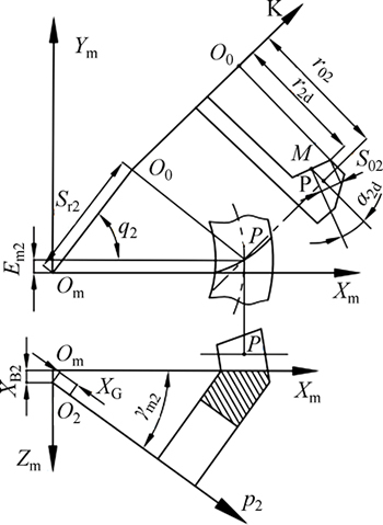
Fig. 2 Coordinate systems applied for gear generation
The gear generating surface  (including the surface and the surface
 can be represented in Sm by the following equation:
 (8)
(8)
The unit normal to the surface  is represented in the fixed coordinate system Sm as follows:
 (9)
(9)
The position vector of  is determined as
 (10)
(10)
The angular velocity of the cradle is 1 for definiteness and without loss of generality, namely,  so the angular velocity of the work gear is
  , where Ra2 is the so-called ratio of roll or velocity ratio. The relative angular velocity and the relative velocity between the generating gear and the work gear are represented as follows:
 (11)
(11)
 (12)
(12)
Equation of meshing may be represented as
 (13)
(13)
Based on Eqs. (9), (12) and (13), the gear surface ��2 (including  and
and  ) can be obtained [14]. Finally, the gear surface is represented in the coordinate system S2 (rigidly connected to the gear) as follows:
 (14)
(14)
The unit normal to the gear surface is determined as
 (15)
(15)
In addition, it is particularly necessary to point out that the formate-cut gear tooth surface is a copy of the surface of head-cutter, which is a surface of revolution. Consequently, the equation of the gear surface is equal to that of the surface of head-cutter.
2.2 Mathematical model of pinion tooth surface
The pinion of a pair of mating spiral bevel and hypoid gears is always cut using the generating method to satisfy the required contact characteristics. However, the mathematical model of the pinion generated by the duplex helical method is completely different from that of the gear and the pinion generated by the five cut process. The duplex helical method is based on the application of a helical motion of the cradle, on which the head cutter is mounted, with respect to the gear blank. Rotation of the cradle is accompanied by an infeed motion of the sliding base, on which the work spindle is mounted.
2.2.1 Generating surface for pinion circular profile head- cutter
The geometry of the circular profile blade for the pinion head-cutter is represented in this section. Figures 3(a), (b) and (c) show illustration of the circular profile blade for the gear head-cutter, the generating tool surfaces for the concave and convex sides, respectively. As shown in Fig. 3, the coordinate system S0{X0, Y0, Z0} is rigidly connected to the pinion head-cutter, Z0 is the axis of the head-cutter, ��1 is the rotation angle, each side of the blade generates two sub-surfaces denoted as parts (a) and (b) of the generating surfaces, the segment of the circular arc (part (a)) with the curvature radius R1 (including the curvature radius of the concave side R1d and the convex side R1c) generates the working part of the gear tooth surface, the circular arc of radius ��1 generates the fillet of the pinion tooth surface (part (b)). ��1 is the pressure angle (including the pressure angle of the concave side ��1d and the convex side ��1c) at the reference point M; S01 is the distance from the top of the blade to the reference point; Pw1 is the point width; r01 is the cutter mean radius; r1 is the cutter point radius (including the pressure angle of the concave side r1d and the convex side r1c); s1 and ��1 are the surface coordinates of the part (a); ��1 and ��1 are the surface coordinates of the part (b). In addition, c0=[0 0 -1]T is the unit vector of the pinion cutter axis; I1 is the tilt angle.
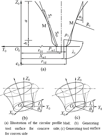
Fig. 3 Circular profile blade and generating revolution surfaces for pinion head-cutter:
Surface  of the pinion head-cutter is represented by vector function r01 as follows:

 (16)
(16)
Baesd on Eq. (3), the unit normal to the pinion generating surface is determined as
 (17)
(17)
The upper and lower signs in Eqs. (16) and (17) correspond to generation of the concave and convex sides of the pinion tooth surface, respectively.
The vector function and the unit normal of the pinion generating surface are similar to that of the gear generating surface (see Section 2.1.2), which are detailed no longer.
2.2.2 Equations of pinion tooth surface
Coordinate system Sm{Xm, Ym, Zm} is rigidly connected to the cutting machine (Fig. 4). The top, bottom and middle of Fig. 4 are the machine front view, the machine bottom view and the side view (the projection of head-cutter). The cradle is rotated about the Ym-axis; the p1-axis is projection of the pinion axes in the XmOmYm-plane. The points P and O0 are the mean contact point and the center of the head cutter, respectively. O2 is the cross point of gear, and Om is the machine center. Some of the machine-tool settings of the given hypoid generator are: the machine root angle of pinion ��m1, the machine center to back XP, the cradle angle of pinion q1, the radial distance of pinion Sr1, the blank offset Em1, the sliding base XB1, the swivel angle J1. In addition,  is the unit vector of the pinion head-cutter, g1=[0 0 1]T is the unit vector of the cradle axis.
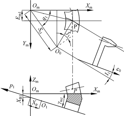
Fig. 4 Coordinate systems applied for pinion generation
The pinion generating surface  and the unit normal (including the surfaceand the surface) can be represented in Sm by the following equations:

 (18)
(18)

 (19)
(19)
The position vector of  is determined as
 (20)
(20)
In general, the angular velocity of the cradle is 1, namely,  so the angular velocity of the pinion is
  where Ra1 is the ratio of roll. The relative angular velocity and the relative velocity between the generating gear and the pinion are represented as follows:
 (21)
(21)
 (22)
(22)
where helical motion velocity coefficient Hl represents a displacement of the pinion blank along the axis of the cradle for a rotational angle of 1 radian of the cradle.
Based on Eqs. (13), (19) and (22), the pinion surfaces  (including
  and
and  can be obtained [14]. Finally, the pinion surface is represented in the coordinate system S1 (rigidly connected to the pinion) as follows:
 (23)
(23)
The unit normal to the pinion surface is obtained as
 (24)
(24)
3 Cases of tooth surface geometry optimization
In order to improve gear contact quality, three types of flank modifications are frequently used in gear industry: profile crowning, lengthwise crowning, and longitudinal twist. In the design of the spiral bevel and hypoid gear, under satisfying a specified accuracy requirement, three types of modifications are blended properly during gear design to absorb assembly and manufacture errors. Circular cutter blades are normally adopted to accomplish the first type modification. The second can be achieved by a cutter radius change or a cutter tilt with adjusted pressure angles. The last can be achieved by a cutter tilt or modified tool path (for example, helical motion and modified roll). As shown in Fig. 5, the circular profile blade is generally applied for modification of the top and root edges of tooth surface, the ideal effect of modification can be obtained by using the appropriate profile radius of curvature.
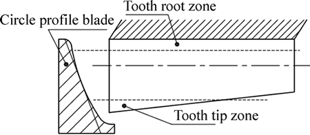
Fig. 5 Profile crowning by circular profile blade
3.1 Example of design and tooth contact analysis of hypoid gear drive
In this section, a computer program was developed to implement establishment of the mathematical model of spiral bevel and hypoid gears generated by duplex helical method with circular profile blades and the tooth contact analysis (TCA). By using this program the influence of a hypoid gear drive 7��43 on tooth contact and transmission errors is investigated. The gear of the gear drive is cut using the formate method, the pinion is cut using the duplex helical method. The design parameters for the hypoid gear drive are listed in Table 1. The basic machine settings are listed in Table 2. The four types of design cases were carried out for comparison, as shown in Table 3.
Figures 6-9 show the path of contact and the contact bearing for four design cases obtained by application of TCA. Comparison of results of contact bearings in Figs. 6-9 has confirmed the following:
1) The contact bearing of Case 1 located at the top edge of the gear tooth surface is the widest and the shortest in 4 design cases, and the orientation angle of the contact path is the smallest for reason of less mismatch at the top and root edges of tooth surfaces.
2) The shape and position of the contact bearings of Case 2 and Case 3 are basically identical, which illustrates that the effect of modifications introduced into the pinion or the gear by applying the same circularprofile blade is the same only for the contact bearing.
3) By comparing Fig. 7 and Fig. 8 with Fig. 6, the contact bearings of the first two are narrower and longer for reason of more mismatch at the top and root edges of tooth surface, and their orientation of path of contact is closer to the longitudinal one, areas of edge contact may be avoided.
4) The length and width of contact bearing of Case 4 are the longest and the widest for reason of the most mismatch at the top and root edges of tooth surface.
5) Mismatch in profile direction can be controlled by the profile radius of curvature, and the convex and concave sides are separately modified by the use of different curvature radii of inside and outside blades, which can increase the flexibility of duplex helical method.
Figrues 10-13 show the function of transmission errors for the four design cases. By comparing results of the functions of transmission errors in Figs. 10-13, the maximum levels of transmission errors for the four design cases are listed in Table 4. The following conclusions can be drawn: the maximum levels of transmission errors for Case 1 and Case 4 are the minimum and maximum in the four design cases, which shows that the more the mismatch is, the greater the maximum levels of transmission errors are only in the case of the same design conditions.
3.2 Application of finite element analysis for contact stress
In the previous section, the results of TCA are carried out under no load. The load history, especially the transfer of load between neighboring gear pair, is very helpful for understanding the gear mesh characteristics. In order to investigate meshing and contact condition of the spiral bevel and hypoid gear drive generated by the duplex helical method with the circular profile blade under load, contact stresses of the four design cases were simulated by applying ABAQUS.
Table 1 Design data
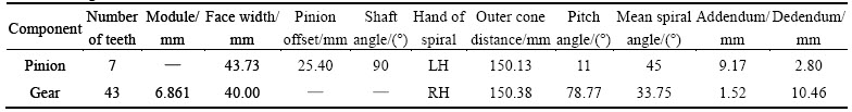
Table 2 Basic machine settings and installment settings of head-cutter
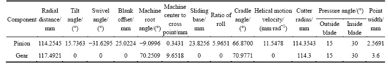
Table 3 Four design cases for hypoid gear drive 7��43
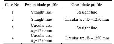
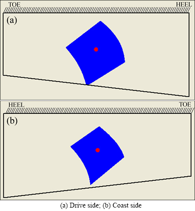
Fig. 6 Contact bearing for Case 1:
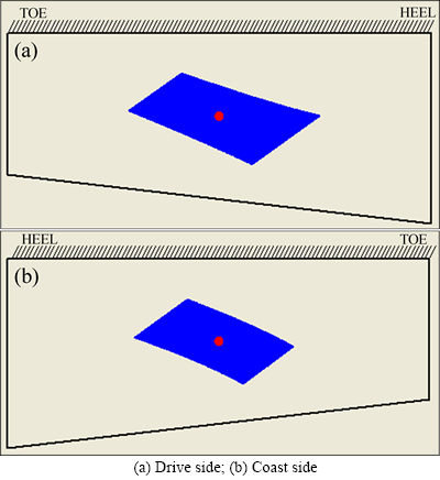
Fig. 7 Contact bearing for Case 2:
Figures 14 and 15 show the evolution of contact stresses for the gear and pinion of the four design cases (for the hypoid gear drive 7��43). For comparison, their maximum contact stresses are listed in Table 5. The torque and the rotational speed applied to the pinion are 500 N��m and 1000 r/min, respectively. The results of investigation of pinion and gear contact stresses are shown in Figs. 14, 15 and Table 5 as follows: 1) There is higher contact stress for reason of impact in the initial phase, with the smooth of the rotational speed, contact stress is gradually stabilizing; 2) The maximum contact stresses of Case 1 and Case 3 for gear and pinion are the highest and lowest in the four design cases, in regard to Case 1, and the maximum contact stresses of Case 3 for the gear and the pinion are reduced by 58.76% and 44.14% by applying the circular profile blades for pinion generation, respectively; 3) The largest decline levels of the gear and pinion contact stresses reach 67.15% and 64.33%, respectively; 4) Areas of severe contact stresses for the gear and pinion are avoided for Case 3 and Case 3 is the best in the four design cases.
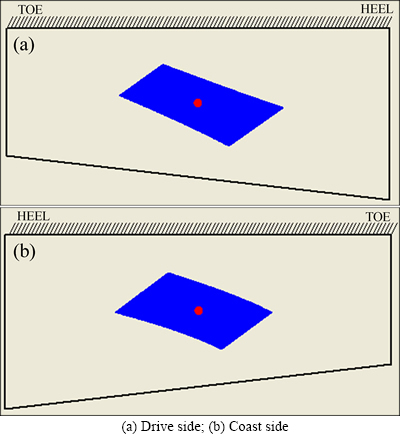
Fig. 8 Contact bearing for Case 3:
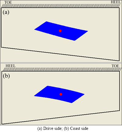
Fig. 9 Contact bearing for Case 4:
3.3 Optimization of profile radius of curvature
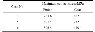
In this section, the influence of modifications introduced into the pinion tooth surface by applying different profile radii of curvature, on contact stress is investigated. The three types of design cases were carried out for comparison, as shown in Table 6. Figures 16 and 17 show the evolution of contact stresses for the gear and pinion of the three design cases, their maximum contact stresses are listed in Table 7. On the basis of the obtained results, the following conclusions can be drawn: 1) For the gear, the maximum contact stress of Case 3 is lowest among the three design cases and for the pinion, the maximum contact stress of Case 3 is the lowest; 2) Considering the whole graph, for the gear or the pinion, Case 3 is considered the best design and therefore it is proposed as the ultimate optimized design for the hypoid gear drive 7��43.
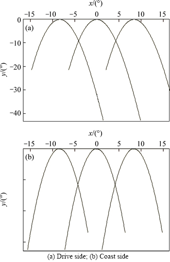
Fig. 10 Function of transmission errors for Case 1:
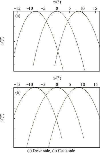
Fig. 11 Function of transmission errors for Case 2:
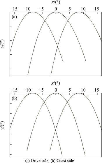
Fig. 12 Function of transmission errors for Case 3:
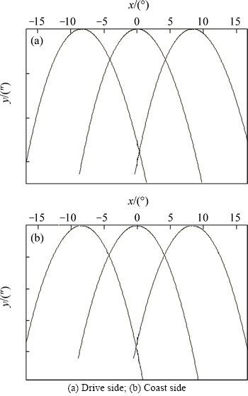
Fig. 13 Function of transmission errors for Case 4:
Table 4 Maximum levels of transmission errors for four design cases
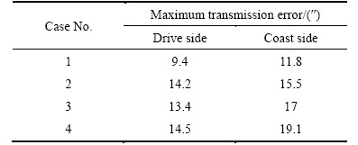
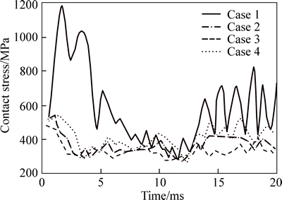
Fig. 14 Gear contact stresses for four design cases
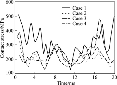
Fig. 15 Pinion contact stresses for four design cases
Table 5 Maximum contact stresses (MPa) for four design cases
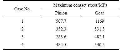
Table 6 Three design cases for the hypoid gear drive 7��43
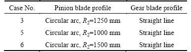
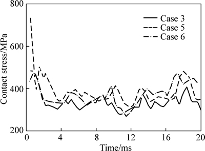
Fig. 16 Gear contact stresses for three design cases
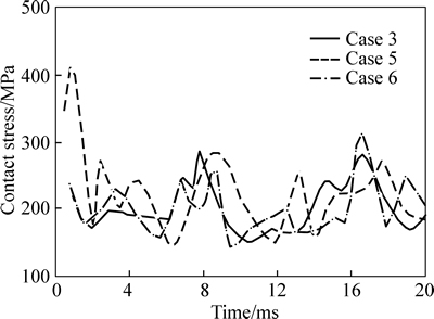
Fig. 17 Pinion contact stresses for three design cases
Table 7 Maximum contact stresses for three design cases
4 Experiments and analysis
In order to verify the effectiveness of the above approach, the cutting and the rolling test experiments of Case 1 and Case 3 are done. Figures 18 and 19 show the tooth bearings on the hypoid gear test machine for Case 1 and Case 3 by the duplex helical method, respectively. The results of the rolling test and the results of TCA (in Fig. 6 and Fig. 8) are carried out under light load. The tooth bearings of the rolling test in Fig. 18 are consistent with the tooth bearings the TCA in Fig. 6; their shapes are wider and shorter, the orientation anglesof the contact path are smaller; they are located at the top edge of the gear tooth surface; areas of the edge contact may appear. The tooth bearings of the rolling test in Fig. 19 are also consistent with the tooth bearings the TCA in Fig. 8. The analysis of the results obtained is as follows: 1) The tooth bears in Fig. 8 and Fig. 19 are all narrower and longer; 2) The orientation angles of the contact path are larger; 3) There are more mismatch at the top and root edges of the pinion surface, so the problem of the appearance of areas of severe contact stress and edge contact can be avoided; 4) The application of the circular blade profile can increase the length of contact bearing, obtain the path of contact closer to longitudinal one, and avoid areas of edge contact. The experiment results in Fig. 18 and Fig. 19 achieve the desired effect. Finally, all of the results show that the problem of the appearance of areas of sever contact stresses and areas of edge contact can be avoided and the contact stresses are availably reduced by application of circular profile blade.
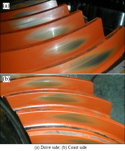
Fig. 18 Tooth bearings on hypoid gear test machine for Case 1:
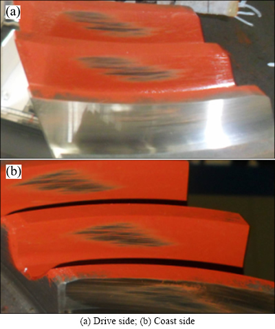
Fig. 19 Tooth bearings on hypoid gear test machine for Case 3:
5 Conclusions
1) Based on the study of the machining characteristics of the duplex helical method, the mathematical model of spiral bevel and hypoid gears generated by the duplex helical method with the circular profile blade is established.
2) The application of the circular blade profile can increase the length of contact bearing, obtain the path of contact closer to longitudinal one, and avoid areas of edge contact.
3) The largest decline levels of the gear and pinion contact stresses reach 67.15% and 64.33%, and areas of edge contact and severe contact stresses can be avoided by optimizing the profile radius of curvature.
4) Mismatch in profile direction can be controlled by the profile radius of curvature, the convex and concave sides are separately modified by the use of different curvature radii of inside blade and outside blade, which can increase the flexibility of duplex helical method.
5) The cutting and rolling test experiment of two pairs of hypoid gear set used the duplex helical method has been performed. The results of the rolling test are consistent with the results of tooth contact analysis, and achieve the desired effect.
References
[1] XIE Shuang-xi. A genuine face milling cutter geometric model for spiral bevel and hypoid gears [J]. International Journal of Advanced Manufacturing Technology, 2013, 67: 2619-2626.
[2] ARTONI A, BRACCI A, GABICCINI M, GUIGGIANI M. Optimization of the loaded contact pattern in hypoid gears by automatic topography modification [J]. ASME Journal of Mechanical Design, 2009, 131: 011008.
[3] STADTFELD H J. Guidelines for modern bevel gear grinding [J]. Gear Technology, 2008: 42-53.
[4] ZENG Tao. Design and manufacture of spiral bevel and hypoid gears [M]. Harbin: Harbin Institute of Technology Press, 1989: 209-218. (in Chinese)
[5] LELKES M, M RIALIGETI J, PLAY D. Numerical determination of cutting parameters for the control of klingelnberg spiral bevel gear geometry [J]. ASME Journal of Mechanical Design, 2002, 124: 761-771.
[6] NIE Shao-wu, DENG Xiao-zhong, LI Tian-xing, ZHANG Hua, DENG Jing. Tooth meshing contact analysis for bevel gears by face hobbing method based on arc blade profile [J]. Journal of Aerospace Power, 2012, 27(6): 1424-1431. (in Chinese)
[7] NIE Shao-wu, DENG Xiao-zhong, SU Jan-xin, GAO Zhen-shan, ZHANG Hua. Flank modification simulation and high-order transmission error design for epicycloid bevel gears [J]. Journal of Machine Design, 2013, 30(5): 32-37. (in Chinese)
[8] KAWASAKI K. Effect of cutting edge profile on meshing and contact of spiral bevel gears in cyclo-palloid system [J]. Mechanics Based Design of Structures and Machines, 2005, 33: 343-357.
[9] SHIH Y P. A lengthwise modification for face-Hobbed straight bevel gears [C]// Proceedings of the ASME 2013 International Design Engineering Technical Conferences and Computers and Information in Engineering Conference. New York: American Society of Mechanical Engineers, 2013: 1-7.
[10] SIMON V. Design of face-hobbed spiral bevel gears with reduced maximum tooth contact pressure and transmission errors [J]. Chinese Journal of Aeronautics, 2013, 26(3): 777-790. (in Chinese)
[11] SIMON V V. Influence of tooth modifications on load distribution in face-hobbed spiral bevel gears [C]// Proceedings of the ASME 2011 International Design Engineering Technical Conferences & Computers and Information in Engineering Conference. New York: American Society of Mechanical Engineers, 2011: 1-13.
[12] SIMON V V. Influence of tooth modifications on tooth contact in face-hobbed spiral bevel gears [J]. Mechanism and Machine Theory, 2011, 46: 1980-1998.
[13] HUSTON R L, COY J J. Surface geometry of circular cut spiral bevel gears [J]. ASME Journal of Mechanical Design, 1982, 104: 743-748.
[14] LITVIN F L, FUENTES A. Gear geometry and applied theory (second edition) [M]. New York: Cambridge University Press, 2004: 627-678.
[15] LITVIN F L, FUENTES A, HAYASAKA K. Design, manufacture, stress analysis, and experimental tests of low-noise high endurance spiral bevel gears [J]. Mechanism and Machine Theory, 2006, 41: 83-118.
[16] FUENTES A, GONZALEZ-PEREZ I, LITVIN F L, HAYASAKA K, YUKISHIMA K. Design, manufacture, and evaluation of prototypes of low-Noise high-endurance spiral bevel gear drives [C]// Proceedings of IDETC/CIE 2005 ASME 2005 International Design Engineering Technical Conferences & Computers and Information in Engineering Conference. New York: American Society of Mechanical Engineers, 2005: DETC2005-84013.
[17] LITVIN F L, WANG A G, HANDSCHUH R F. Computerized generation and simulation of meshing and contact of spiral bevel gears with improved geometry [J]. Computer Methods in Applied Mechanics and Engineering, 1998, 158: 35-64.
[18] SIMON V. Head-cutter for optimal tooth modifications in spiral bevel gears [J]. Mechanism and Machine Theory, 2009, 44: 1420-1435.
[19] SIMON V. Optimal modifications of gear tooth surfaces [J]. Gear Technology, 2011: 62-72.
(Edited by DENG L��-xiang)
Foundation item: Project(2011CB706800-G) supported by the National Basic Research Program of China; Project(51375159) supported by the National Natural Science Foundation of China; Project(20120162110004) supported by the Postdoctoral Science Foundation of China; Project(2015JJ5020) supported by the Science Foundation of Hunan Province, China
Received date: 2015-01-11; Accepted date: 2015-06-11
Corresponding author: YAN Hong-zhi, Professor, PhD; Tel: +86-731-88876612; E-mail: yhzcsu@mail.csu.edu.cn
Abstract: In order to effectively improve meshing performance of spiral bevel and hypoid gears generated by the duplex helical method, the effects of straight lined and circular cutting edges profile on meshing and contact of spiral bevel and hypoid gears were investigated analytically. Firstly, a mathematical model of spiral bevel and hypoid gears with circular blade profile was established according to the cutting characteristics of the duplex helical method. Based on a hypoid gear drive, the tooth bearings and the functions of transmission errors of four design cases were analyzed respectively by the use of the tooth contact analysis (TCA), and the contact stresses of the four design cases were analyzed and compared using simulation software. Finally, the curvature radius of the circular profile blade was optimized. The results show that the contact stresses are availably reduced, and the areas of edge contact and severe contact stresses can be avoided by selecting appropriate circular blade profile. In addition, the convex and concave sides are separately modified by the use of different curvature radii of inside and outside blades, which can increase the flexibility of the duplex helical method.
