
�й���ɫ����ѧ�� 2003,(06),1343-1349 DOI:10.19476/j.ysxb.1004.0609.2003.06.004
��ͼ�����ڵ��Ӳ��Ϻ����е�Ӧ��
���ϴ�ѧ���Ͽ�ѧ�빤��ѧԺ,���ϴ�ѧ���Ͽ�ѧ�빤��ѧԺ,���ϴ�ѧ���Ͽ�ѧ�빤��ѧԺ ��ɳ410083 ,��ɳ410083,���ϴ�ѧ��ĩұ������ص�ʵ����,��ɳ410083 ,��ɳ410083
ժ Ҫ��
���������Ľ��淴Ӧ�Ը����ܵ��Ӳ��Ϻ��ӽ�ͷ����ѧ���ܺͿɿ��Զ����ź���Ҫ��Ӱ�졣�Ѻ��ӹ��̷�Ϊ���淴Ӧ��ʣ�ຸ�������������̽������� ,����ͼ����ѧ�Ļ����� ,ͨ������������ͼ���ȽϽ��洦�ֲ�ƽ��ʱ�����γ���������С ,Ԥ����Sn 3.5 %Ag/Cu��Sn 2 5 %Ag/Cu��Sn 3.5 %Ag/Ni��ɢż���淴Ӧ�����е��м����γ����� ;ͬʱ����Scheil Gulliver����ģ��ģ����Sn 2 5 %Ag/Cu��ϵ�й�ʣ���ϵķ�ƽ�����̹��� ,Ԥ���˺����������ȴ�����е����ݱ���Ϣ������Ԥ��Ľ����ǰ�˵�ʵ�����ǺϺܺá�
�ؼ��ʣ�
��Ǧ����;���淴Ӧ;��Ӧͨ��;��ͼ����;�м仯����;
��ͼ����ţ� TG44
����飺������(1978),��,˶ʿ,�绰:07318836209,Email:jin@mail.csu.edu.cn;
�ո����ڣ�2003-01-03
�������ϴ�ѧ������������������Ŀ (760 89);
Application of CALPHAD in soldering of electronic materials
Abstract��
It is believed that reaction products in the interface between solder and substrate have great effects on mechanical properties and reliability of the solder/substrate joint. Based on the calculations of metastable phase equilibria between the solder and the substrate and the comparison of the driving forces of formation of inpidual intermetallic compounds, a thermodynamics method was used to predict the formation sequence of the intermetallic compounds during the interfacial reaction period. This method was applied to the interfacial reaction of Sn-3.5%Ag/Cu, Sn-25%Ag/Cu, and Sn-3.5%Ag/Ni solder/substrate systems. In addition, by using Scheil-Gulliver model, the non-equilibrium solidification of Sn-25%Ag/Cu system was modeled and the microstructure evolution was also predicted. The results from thermodynamic calculations are in good agreement with previously reported experiments.
Keyword��
lead-free solder; interfacial reaction; reaction path; CALPHAD technique; intermetallics;
Received�� 2003-01-03
����ʱ�м仯��������ɺͳ���Ժ���Ŀɿ����кܴ��Ӱ�졣 �����������м仯�������������ʪ�����ӵı�Ҫ����, ͬʱ�ܴ����ߺ������ѧ����; ���ڱ������еĴ���, ̫����м仯�������ͺ���Ŀɿ��ԡ� ����, �ں��Ӻ��ʱЧ��ʹ���ڼ�, �м����������������п��������µ��м���, ��Щ����֯�ı仯������Ӱ�캸��Ŀɿ������ķ�չʹ����Խ��ԽС(10-4��10-5 mm3)
1 ����������
������ɢ���ƵĽ��淴Ӧ�;ֲ�ƽ������, Lee
1.1 ���淴Ӧ��Ԥ��
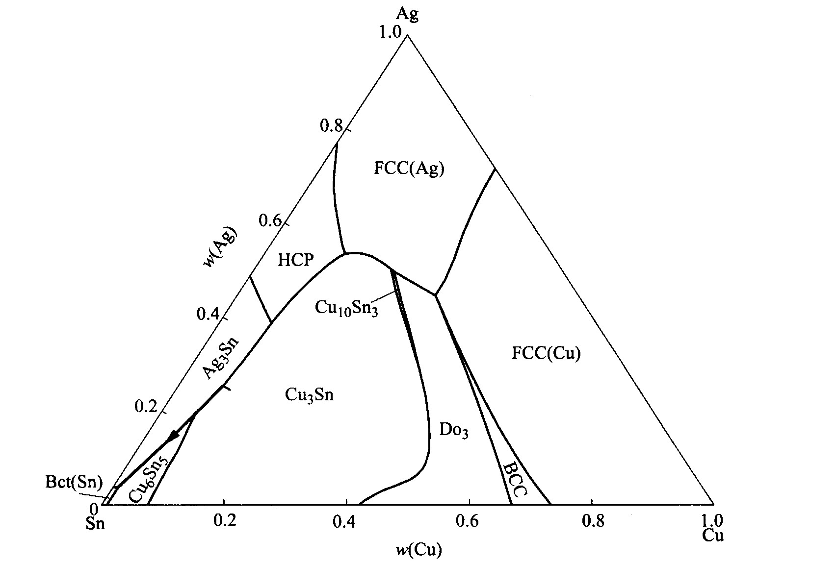
������Sn-3.5%Ag/Cu��513 K�µ�Һ����ɢżΪ��˵����ͼ������Ԥ�⺸���������淴Ӧ�е�Ӧ�á� ��Sn-Ag-Cu��Ԫϵ��, ����Ag��Cu����FCC�ṹ��֮����ڹ��ܶȼ�϶, ���淴Ӧ��ʼʱҺ̬����ֱ�������Ӵ�, ������Ϊϵͳ����Һ�ࡢ FCC(Ag)��FCC(Cu)3����, ��ֻ��Һ/FCC(Cu)һ�����档 ��Sn-Ag-Cu��Ԫϵ����ѧ��������
Ȼ��, �����м����Шʽ��ɢ�����ļ���, �ѵ�һ��Ԥ��õ����м���Cu6Sn5���뵽ƽ����������� ��ʱ, ���������Ľ�����2��, ��Һ��/Cu6Sn5��Cu6Sn5/FCC(Cu)�� ������ѧ����õ�����Һ�ࡢ FCC(Ag)�� FCC(Cu)��Cu6Sn5��������ͼ, ��ͼ2��ʾ�� ����Cu6Sn5������, Һ����Ag�ĺ�������, ���Խ��洦Һ��ľֲ�����ɷ�����Һ������Ag���ƶ���B1�㡣 ����ȱ������ѧ����, ��ʱ����ȷȷ��B1���λ��, ��ʵ���ϼ������, ��Һ��+Cu6Sn5�������в�ͬ���ߵļ��������� ������B1�ɽ��ƴ�����ʱ�ľֲ�����ɷ֡� ���ݾֲ�ƽ��ĸ���, ���Ƿֱ������ϵͳ��B1E��EF���������������ľֲ�ƽ��״̬�¸�����γ���������С, ���2��3��ʾ�� �ɼ�����Һ��/Cu6Sn5������û����ƽ����������γ���������Ϊ��ֵ, ��û�������ڴ˽�������, ����Cu6Sn5/FCC(Cu)���洦, Cu3Sn���γ������������Ϊ��ֵ�� ͬ������ǰ��ļ���, ���Եõ�Cu3Sn���ǵڶ����������м��ࡣ
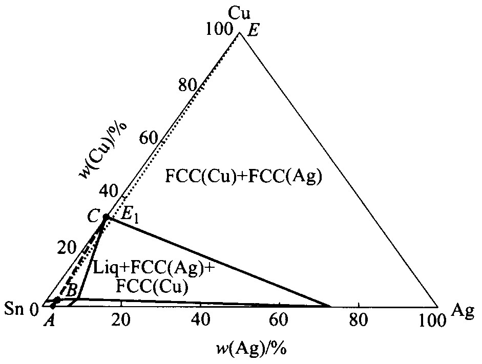
ͼ1 Sn-Ag-Cu��513 K�µĵ�һ�� ����״̬�ĵ��½���(Liq+FCC(Ag)+FCC(Cu))
Fig.1 Isothermal section of Sn-Ag-Cu at 513 K at the first metastable stage (Liq+FCC(Ag)+FCC(Cu)) (Dashed line connects solder and substrate, dotted line is the tie line at this local equilibrium)
��1 Sn-3.5%Ag/Cu��513 Kʱ��һ������״̬��Һ+FCC(Cu)����ƽ��ʱ������γ�������
Table 1 Calculation of driving force (��G) forformation of IMC phases at 513 K forSn-3.5%Ag/Cu joint in first metastablestage between liquid and FCC(Cu)
Phase |
Status | Driving force ��G/ (J��mol-1) |
Mole fraction |
Liquid |
Entered | 0 | 0.822 |
FCC(Cu) |
Entered | 0 | 0.178 |
FCC(Ag) |
Entered | -0.957 | |
Cu6Sn5 |
Dormant | 0.332 | |
As3Sn |
Dormant | 0.229 | |
Cu3Sn |
Dormant | 0.205 | |
Cu10Sn3 |
Dormant | -0.042 | |
��G of all other phases are negative |
|||
Entered��ʾ����ƽ��������, Dormant��ʾ������ƽ�����������������
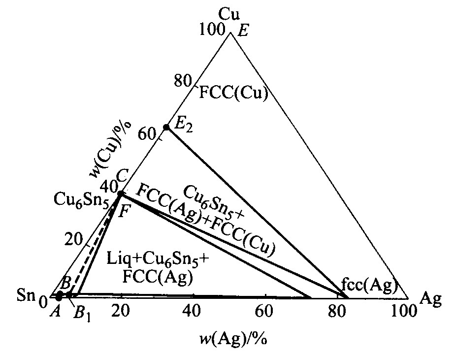
ͼ2 Sn-Ag-Cu��513 K�µĵڶ��� ����״̬�ĵ��½���(Liq+FCC(Ag)+ FCC(Cu)+Cu6Sn5)
Fig.2 Isothermal section of Sn-Ag-Cu at 513 K at the second metastable stage (Liq+FCC(Ag)+FCC(Cu)+Cu6Sn5) (Dashed line is the tie line at this local equilibrium)
��2 Sn-3.5%Ag/Cu��513 K�ڶ�������״̬��Һ��+Cu6Sn5����ƽ��ʱ������γ�������
Table 2 Calculation of driving force (��G) forformation of IMC phases at 513 K forSn-3.5%Ag/Cu joint in the second metastablestage between liquid and Cu6Sn5
Phase |
Status | Driving force ��G/ (J��mol-1) |
Mole fraction |
Cu6Sn5 |
Entered | 0 | 0.109 |
Liquid |
Entered | 0 | 0.891 |
FCC (Ag) |
Entered | -0.256 | |
FCC (Cu) |
Entered | -0.278 | |
��G of all other phases are negative |
|||
��3 Sn-3.5%Ag/Cu��513 K�ڶ�������״̬��FCC(Cu)+ Cu6Sn5����ƽ��ʱ�����������
Table 3 Calculation of driving force (��G) forformation of IMC phases at 513 K forSn-3.5%Ag/Cu joint in the second metastablestage between FCC(Cu) and Cu6Sn5
Phase |
Status | Driving force ��G/ (J��mol-1) |
Mole fraction |
FCC(Cu) |
Entered | 0 | 0.690 |
Cu6Sn5 |
Entered | 0 | 0.310 |
FCC(Ag) |
Entered | -0.715 | |
Liquid |
Entered | -0.993 | |
Cu3Sn |
Dormant | 0.728 | |
Cu10Sn3 |
Dormant | 0.555 | |
Cu41Sn11 |
Dormant | 0.495 | |
��G of all other phases are negative |
|||
�����Ӧʱ���㹻��, һֱ���Խ��е�û�в���ƽ����������γ���������Ϊ��, ����û���µ��м�������Ϊֹ�� ����, ��Cu3SnҲ�ӵ�ƽ������, ͬ������ǰ���ģ��, ��������µĽ��洦�ֲ�ƽ��ʱ������γ��������� �����������û�в���ƽ����������γ���������Ϊ��ֵ, �����ӵĵ�һ�ν��淴Ӧ������ ��Ҳ˵����Chen
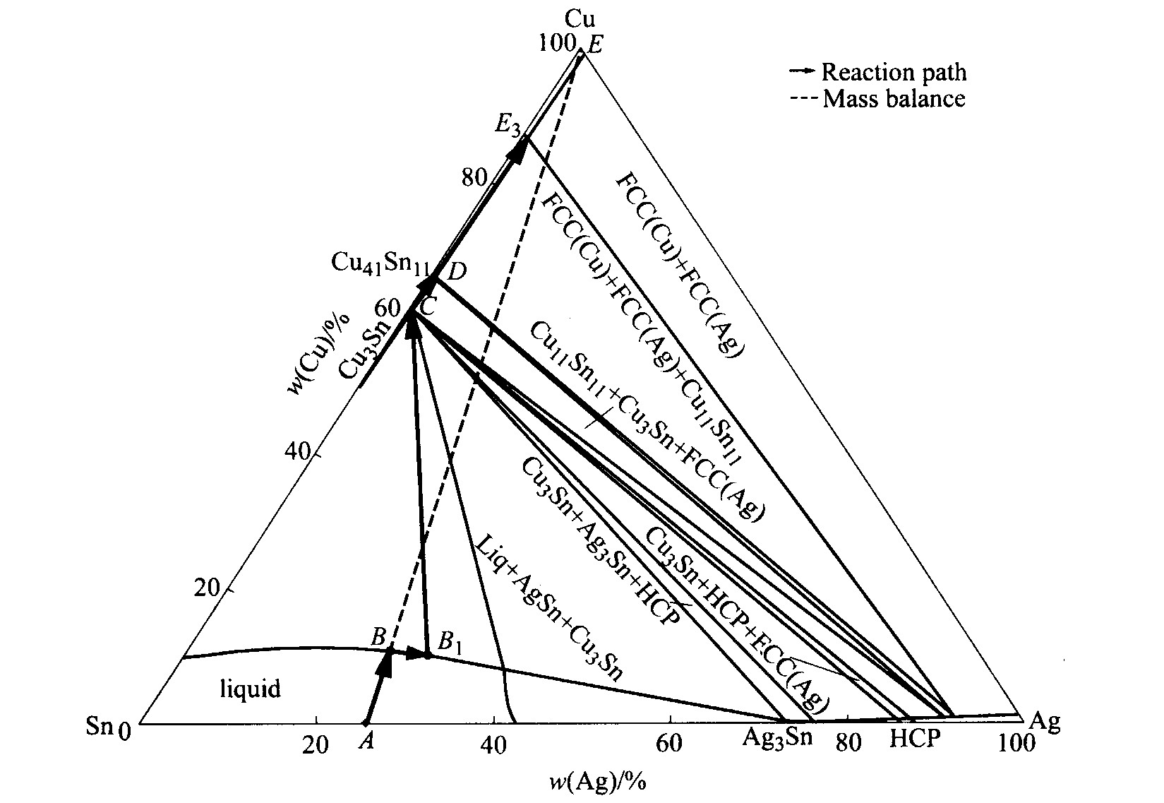
����������������Ԥ���ڲ�ͬ�¶��²�ͬ�ɷֵ�Sn-Ag�Ͻ���Cu����ɢż���淴Ӧ�� ��Ԥ��Sn-25%Ag/Cu��ɢż��723 K�½��淴Ӧ�����м�����γ����С� ����, ����ֻ����Һ�ࡢ FCC(Cu)�� FCC(Ag)3������723 K�µĵ��½���, ����һ������(AE)���Ӻ��������, ��������������Һ��+FCC(Cu)�����ཻ��B��, ����˽���BC�����ľֲ�ƽ��״̬�¸����γ���������С, �������Cu3Sn���γ������������Ϊ��ֵ, ����Һ��/FCC(Cu)���洦��������Cu3Sn�ࡣ Ȼ��, ��Cu3Sn���뵽ƽ���������, �ֱ������洦B1C��CD����������������ƽ��״̬�¸�����γ���������С, �����ʾ����Һ��/Cu3Sn�������γ���������Ϊ��ֵ, ��û�������ڴ˽����γ�, ������Cu3Sn/FCC(Cu)��Cu41Sn11���γ������������Ϊ��ֵ, ��Cu41Sn11�������� ��������ֱ��������û���γ�������Ϊ������, �����淴Ӧ�ν����� �ɴ˿��Եõ�Sn-25%Ag/Cu��ɢż��723 K�Ľ��淴Ӧ�м����γ�����Ϊ: Cu3Sn��Cu41Sn11�� ��ͼ4��ʾ: ��Sn-Ag-Cu 513 Kʱ�ĵ��½��������Sn-3.5%Ag/Cu��ɢż723 K�µķ�Ӧͨ��, �䷴Ӧͨ��Ҳ������Ϊ: A��B��B1��C��D��E3�� ����Chen
��Cu֮��, Ni, Au, Pd�dz�������������赲��IJ��ϡ� ���Ԥ�⺸������Щ���������Ľ��淴Ӧͬ������ʵ��Ӧ�ü�ֵ�� Ϊ��, ͬ��������������Ԥ����Sn-Ag/Ni��ɢż���淴Ӧ�м仯������γ����С� ��4����ΪSn-3.5%Ag/Ni��ɢż723 K�½��淴Ӧ��ʼ�θ����γ���������С�ıȽ����, ���п��Եõ�Ni3Sn4���γ������������Ϊ��ֵ, ��Ni3Sn4��Sn-3.5%Ag/Ni����ĵ�һ����Ӧ��� ��5�ͱ�6ΪSn-3.5%Ag/Ni��ɢż�������и�����γ���������С�ıȽ����, ���п��Եõ�����Һ��/Ni3Sn4���м仯��������, ������Ni3Sn4/(Ni)����Ni3Sn����, �Ӷ��õ�����ɢż523 K���淴Ӧ�м仯������������Ϊ: Ni3Sn4��Ni3Sn�� ��Ҳ������

ͼ3 Sn-Ag-Cu��513 K�ĵ��½����Sn-3.5%Ag/Cu��ɢż�ķ�Ӧͨ��
Fig.3 Reaction path of Sn-3.5%Ag/Cu couple reacted at 513 K superimposed with Ag-Sn-Cu 513 K isothermal section(A��B��B1��C��D��E3)
ͼ4 Sn-Ag-Cu��723 K�ĵ��½����Sn-25%Ag/Cu��ɢż�ķ�Ӧͨ��
Fig.4 Reaction path of Sn-25%Ag/Cu couple reacted at 723 K superimposed with Ag-Sn-Cu 723 K isothermal section(A��B��B1��C��D��E3)
��4 Sn-3.5%Ag/Ni 723 K��һ������״̬��Һ��+FCC(Ag)����ƽ��ʱ������γ�������
Table 4 Calculation of driving force (��G) forformation of IMC phases at 723 K forSn-3.5%Ag/Ni joint in the first metastablestage between liquid and FCC(Ag)
Phase |
Status | Driving force ��G/ (J��mol-1) |
Mole fraction |
FCC(Ag) |
Entered | 0 | 0.037 |
liquid |
Entered | 0 | 0.963 |
FCC(Ni) |
Entered | -0.027 | |
Ni3Sn4 |
Dormant | 0.945 | |
Ni3Sn2 |
Dormant | 0.498 | |
Ni3Sn |
Dormant | 0.361 | |
��G of all other phases are negative |
|||
��5 Sn-3.5%Ag/Ni 723 K�ڶ�������״̬��Һ+Ni3Sn4����ƽ��ʱ������γ�������
Table 5 Calculation of driving force (��G) forformation of IMC phases at 723 K forSn-3.5%Ag/Ni joint in the second metastablestage between liquid and Ni3Sn4
Phase |
Status | Driving force ��G/ (J��mol-1) |
Mole fraction |
Ni3Sn4 |
Entered | 0 | 0.425 |
liquid |
Entered | 0 | 0.575 |
FCC(Ni) |
Entered | -0.464 | |
FCC(Ag) |
Entered | -0.821 | |
��G of all other phases are negative |
|||
1.2 ��ƽ�����̹��̵�ģ��
������Sn-25%Ag/Cu��723 K�¹�Һ��ɢżΪ��˵����ͼ�����ڷ�ƽ�����̹���ģ���е�Ӧ�á�
����ȱ����ϵͳ�Ķ���ѧ����, ����ȷȷ�����洦�����ڸ��ε�ʵ�ʳɷ֡� ����, ����ͼ4��ʾ Sn-Ag-Cu��Ԫϵ723 K�ĵ��½���ɹ���Sn-25%Ag/Cu��ɢż���淴Ӧ����ʱʣ�ຸ���ڽ��洦������ɷ�ΪSn-24%Ag-10%Cu�� ����Scheil-Gulliverģ��, �ں���������, ����õ�����������¶ȱ仯������ͼ5��ʾ�� �ɼ��óɷֵĺϽ������̹����п��ܻ�����Cu3Sn�� Ag3Sn��Cu6Sn5���м��ࡣ Chen
��6 Sn-3.5%Ag/Ni 723 K�ڶ�������״̬��Ni3Sn4+FCC(Ni)����ƽ��ʱ������γ�������
Table 6 Calculation of driving force (��G) forformation of IMC phases at 723 K forSn-3.5%Ag/Ni joint in the second metastablestage between Ni3Sn4 and FCC(Ni)
Phase |
Status | Driving force ��G/ (J��mol-1) |
Mole fraction |
Ni3Sn4 |
Entered | 0 | 0.710 |
FCC(Ni) |
Entered | 0 | 0.290 |
FCC(Ag) |
Entered | 0 | |
Liquid |
Entered | -1.365 | |
Ni3Sn |
Dormant | 2.156 | |
Ni3Sn2 |
Dormant | 1.934 | |
��G of all other phases are negative |
|||
���ϼ����ʵ�����ıȽϱ���, �����þֲ�ƽ�����۵Ļ�����, ��ͼ���㼼����һ���о���������ļ����ݱ�ĺ����õĹ��ߡ� ��Ȼ, ���о����������֮������ݱ����ʱ, ����Ҫ�����γ���������С�ͺ�����������������С֮��, �м���ı����ܴ�С�� ���Ӻ���ȴ��������Ҳ�Ǻ���Ҫ��Ӱ�����ء� ͬʱ, ���洦�ľֲ�����ɷֵľ�ȷȷ����Ҫϵͳ�Ķ���ѧ����, ���Դ˷�����ʱ�������ľ����ԡ� ���Ǽ����ʵ�����������, ��ȱ�������ܺͶ���ѧ�����ݵ������, ���þֲ�ƽ�����ۺ;ֲ�����ɷֵĸ���, ����Ԥ������淴Ӧ�����̹����Ǻ����ġ�
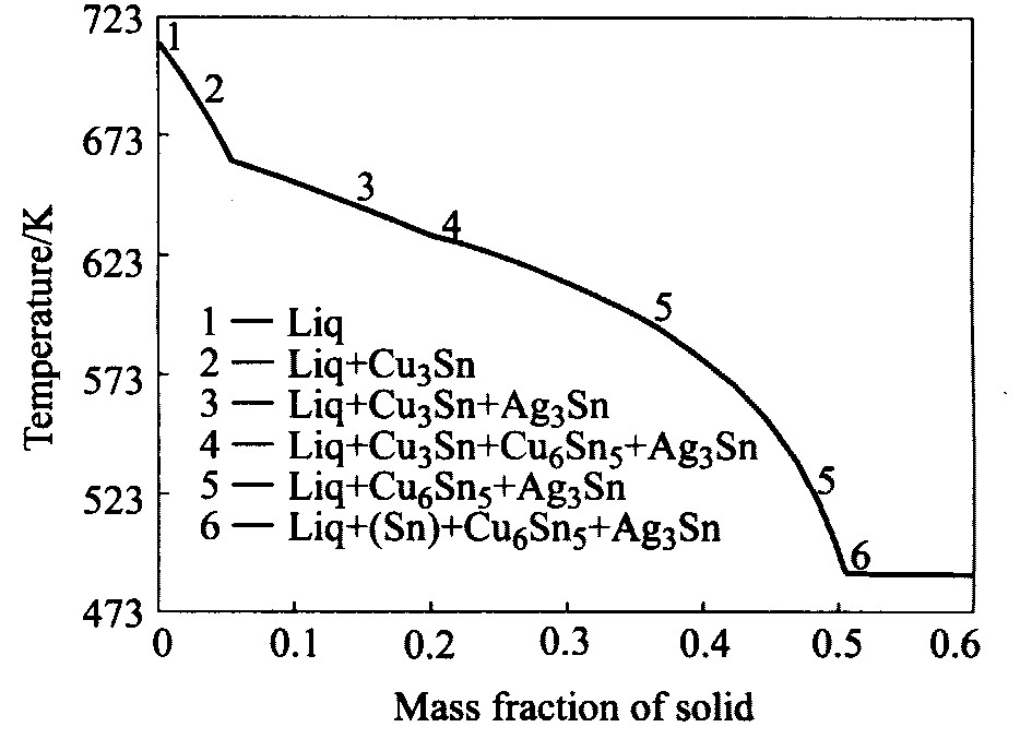
ͼ5 ����Scheilģ�ͼ���ĺϽ�Sn-24%Ag-10%Cu ��ƽ�����̹����й���������¶ȱ仯����
Fig.5 Calculated mass fraction of solid phase during Scheil solidification for alloy Sn-24%Ag-10%Cu
ͼ6 ����ɷֺϽ�Sn-24%Ag-10%Cu������ͨ��(Scheilģ��) ���ӵ�Sn-Ag-Cu��ԪϵҺ����ͶӰ��ʱ�����
Fig.6 Solidification path during Scheil solidification for alloy Sn-24%Ag-10%Cu superimposed with Sn-Ag-Cu liquid projection
2 ����
1) ������ͼ����ѧ����;ֲ�ƽ�����ۺܺõ�Ԥ���˺��������Ľ��淴Ӧ�� ͨ������������ͼ�� �ȽϽ��洦�ֲ�ƽ��ʱ�����γ���������С, Ԥ����Sn-3.5%Ag/Cu��Sn-25%Ag/Cu��ɢż���淴Ӧ�����е��м����γ����С�
2) ����Scheil-Gulliver����ģ��ģ����Sn-25%Ag/Cu��ϵ723 K�¹�ʣ���ϵķ�ƽ�����̹���, Ԥ���˺����������ȴ�����е����ݱ���Ϣ�� ����Ľ����ǰ�˵�ʵ�����ǺϺܺ�, ���ܺ����ؽ����й�ʵ������ Ϊ������Ǧ���ϺϽ�ijɷֺͽ������(������к��������)�ͺ��ӹ��յ��Ż�(�纸�Ӻ��ȴ����¶ȵ�ѡ��)�ṩ���������ݡ�
�����
[3] ��GayleFW ,BeckaG .Hightemperaturelead freesolderformicroelectronics[J].JOM ,2001,6:1721.
[4] ��FrearDR ,JangJW .Pb freesolderforflip chipinter connects[J].JOM ,2001,6:2832.
[6] ��KirkadyJS ,YoungDJ .DiffusionintheCondensedState[M].London:TheInstituteofMetals,1987.
[8] ��SaundersN ,ModwnikAP ,CALPHAD AComprehen siveGuide[M ].LausanneSwitzerland,Pergamon,1998.
[9] ��SundmanB ,JanssonB ,AndersonTO .Thermo calcdatabooksystem[J].CALPHAD ,1985,9:153.
[12] ��GurD ,BamaergerM .ReactiveisothermalsolidificationintheNiSnsystem[J].ActaMater,1998.46:4917.
