
Article ID: 1003-6326(2005)06-1367-06
Novel electrodeposition process for preparing
hydroxyapatite coating on titanium substrate
ZHAO Zhong-wei(����ΰ)1, LI Hong-gui(����)1,
SUN Pei-mei(����÷)1, CHEN Xing-yu(������)1, Okido Masazumi2
(1. School of Metallurgical Science and Engineering, Central South University,
Changsha 410083, Hunan;
2. Department of Materials Science, School of Engineering, Nagoya University,
Nagoya 464-8603, Japan)
Abstract:
A novel process for electrodeposition of hydroxyapatite coating on titanium substrate was developed. The mechanism of the electrochemical reaction on the cathode was changed by adding H2O2 into the electrolyte. The evolution of H2 gas was erased. And owing to the fact that H2O2 posesses high tendency of being reduced, a fairly high cathodic current can be gained at a more positive potential than -1.0V. During the electrodeposition, 6%H2O2 is added, the temperature of deposition is fixed at 55�� and pH of electrolyte is adjusted to 5.5. Dense and homogeneous film is crystallized at high rate. The mechanism of crystallize process was discussed.
Key words:
electrodeposition; hydroxyapatite; polarization CLC;
number: TQ174 Document code: A
1 INTRODUCTION
Various methods have been developed to deposit calcium phosphate, especially hydroxyapatite(HAp) film on the orthopedic alloys, which makes use of both the excellent biocompatibility of HAp and high mechanical strength of alloy materials[1-3]. Plasma spraying[4, 5] is the most commonly used method, but the high operational temperature leads to decomposition and phase transformation of HAp during the coating process. Additionally, the adhesion of coating to the substrate is not reliable. Another shortage is that the plasma spraying is a line-in-sight process that becomes inefficient when applied to substrate of complex shape. Beside, it is an intensive energy process. The sol-gel process[6] is a long flow-sheet repeating process and also faces the trouble of adhesion. A pre-treatment by sintering can make things better, but it may change the structure of deposit and substrate. Electrophoretic method[7], though possessing high adaptability to irregular shaped material, has to apply high voltage to drive the suspended particle onto metal surface. The anodic polarization may cause the corrosion of metal and its adhesion is not good.
On the other hand, the electrochemical method has attracted considerable attention since it is superior to others in low operating temperature and high adaptability for depositing on substrates of various shapes[8-10]. Compared with the electrophoretic method, the substrate is cathodically polarized during deposition, and can obviously minimize corrosion.
In this process, on the cathodically polarized electrode H2O and/or H+ is reduced according to
2H2O+2e=H2+2OH-(1)
2H++2e=H2(2)
These reactions lead to the increase of local pH at the close vicinity of cathode/solution interface as a result of production of OH- ions and consumption of H+ ions. Once the super-saturation of calcium phosphate exceeds the critical level, nuclei forms on the substrate and grows into bioceramic film[9].
But H2 gas generated on the surface of electrode inhibits the nucleation and growth of Hap coating, which causes some problems[11]. Besides, for the high stability of H2O and the large over-potential of electrochemical reaction, an applied potential of about -1.6V (vs SCE) is needed. Ban et al[12] even applied a potential of -2V (vs SCE) to the cathode.
It has been argued that the reduction of NO-3 ions are partially used to it[13]
NO-3+H2O+2e=NO-2+2OH-
��0=0.01V (vs SHE)
But according to Yen��s work[14], NO-3 is indeed fairly stable on Ti cathode in the solution with pH ranges of 2.2-7.0 and applied potential of 0-4V (vs SCE).
Chen et al[11] has tried to depress the evolution of H2 gas by adding ethyl alcohol into the electrolyte. But it needs to add the organic substance more than 50% of the electrolyte, which leads to high solution resistance. Thus cell voltage up to 25V has to be applied.
It has been noticed that H2O2 , hydrogen peroxide, is a strong oxidative reagent and can be reduced on cathode, only produce OH- ions as
H2O2+2e=2OH-
��0=0.95V (vs SHE)
It is expected that the shortcomings of traditional process, such as H2 evolution and intensive polarization, can be overcome by introducing H2O2 into the electrolyte. It is also reported[15 ] that highly hydroxylated surface can be obtained by treating titanium in H2O2 solution. The surface is beneficial for nucleation of HAp owing to the fact which provides crystal lattice matching, hydrogen bonding interaction as well as stereo-chemical matching between the OH- groups chemically absorbed and HAp crystal.
Actually, by applying a modified solution in which H2O2 is introduced, the H2 evolution has been erased and dense brushite coatings also successfully deposits on titanium substrate at a weaker polarization potential of -0.8V (vs SCE)[16]. This paper gives a report on the electrodeposition of HAp film by the new method.
2 EXPERIMENTAL
The electrolyte used is prepared by dissolving CaH2PO4��H2O and CaCl2��2H2O in 200mL distilled water. The total concentration of calcium and phosphate are 0.01mol/L and 0.006mol/L, respectively. The concentration of H2O2 is 6%(mass fraction). The pH value of electrolyte is adjusted to 5.5 by adding NaOH or HCl solution. The anode electrode is a platinum coil. Rectangular sample titanium of 10mm��10mm is used as cathode for deposition of HAp. The sample is metallographically polished using an emery paper of 200 grit and washed with distilled water before experiments. A microcomputer-controlled electrochemical system(Solartron) is used to conduct experiments.
The coatings were characterized by X-ray diffractometry. The morphology and thickness of coatings were observed by scanning electron microscopy.
3 RESULTS AND DISCUSSION
3.1 Cathodic polarization
The cathodic polarization results are shown in Fig.1.
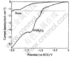
Fig.1 Cathodic polarization curves for titanium electrode
For the solution without H2O2 addition, the cathodic current keeps low. When the potential is more than -0.6V, no apparent current can be detected. The limited current corresponding to potential range of -0.7-1.3V can be attributed to the diffusion mass transport limit of O2 dissolved[14]. When potential exceeds -1.3V, the current density begins to increase. At the meantime, bubble starts to evolve from the electrode surface and becomes more vigorous with increasing potential. This may be attributed to the H2 gas produced through the reduction of water through Eqn.(1).
Since the coating deposition needs an intense enough cathodic current to sustain the high pH in the close vicinity of electrode and this can only be obtained when the applied cathodic potential is more intensive than -1.3V, the traditional process have to be operated at -1.6V or even more negative[17].
By contrast, for the solution with H2O2 addition, cathodic current begins to increase at -0.2V and reaches up to as several times as before by adding H2O2 in the solution. It is valuable to notice that no bubble evolves from electrode throughout the whole scanning range when H2O2 is added.
Apparently, H2O2 in the electrolyte has greatly enhanced the electrochemical process at the electrode/solution interface. For example, it can be shown in Fig.1 that a cathodic current of about 0.8mA/cm2 will flow through the electrode at -1.6V when using the traditional electrolyte. But the same current can be obtained at the potential of -0.8V after adding H2O2 into the electrolyte. According to mentioned above, H2O2 appears to be a hopeful additive for modifying the traditional electrolyte.
3.2 Electrochemical deposition
3.2.1 Effect of H2O2 addition and time
Fig.2 shows the kinetic curves for the growth of film at -0.8V in the solution with H2O2 addition and at -1.6V in the solution without H2O2, respectively. The film grown in the modified electrolyte seems to be thicker than that from traditional one. Within the same time of 500s, the rapidity of film growing using the new method is as two times as that of the old one. The lower rate can be attributed to relatively lower driving force, or lower super saturation in the close vicinity of the electrode surface. Noticing the fact that the same amount of OH- ions are produced within the same time interval since the cathodic current are almost the same at the beginning of the 2 experiments, we consider that evolving of H2 gas from the electrode evoke intense convection and depress the local pH too. Another side effect of H2 gas is its occupying the active surface sites and inhibiting the precipitation of hydroxyapatite.
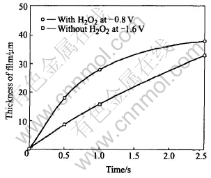
Fig.2 Kinetic curves for growth of film under different conditions
The deposition in the new electrolyte gradually slows down and makes the curve into parabolic-shaped. This implies that cathodic reaction is under the control of diffusion through dense film formed. On the contrary, it only bents slightly when using a traditional electrolyte and shows almost a straight line. So the electrochemical reaction is still under kinetic control. The film deposited which should be loose and fair can not inhibit the diffusion of ions through it. In fact, the film is so weak that sometimes part of it exuviates when washed the surface with distilled water.
This can be confirmed by comparing the crossection view in Fig.3 for samples deposited from two kinds of solutions. They are both suffered mechanical damage by SiC particles. But the images obtained show that the coating by new method is still adhered while that by traditional method almost lost contact with substrate.
The top view of coatings by new method exhibits a scaling-liked morphology which is densely compacted by plate crystal. It seems that the plate has grown into each other at the junction. But the coatings from a traditional electrolyte is composed of long zonal crystal which has grown from the inner part of the film towards the outer.
The XRD spectrum reveals that the two coatings are hydroxyapatite. But from Fig.3, the peaks of HAp is much intensive, which shows that the coatings by new method are of relatively high crystallinity. The interesting fact noteworthy is that on the XRD spectrum of sample by new method, the peak of (0002) plane is superior to other plane overwhelmingly. This demonstrates that the highly oriented HAp nucleates on the (0001) plane parallel to the substrate surface as reported by Mao et al[15] who deposited HAp coatings by a boimimic method on titanium pretreated with H2O2 . It is plausible that this deposition process is similar to that of Mao��s, but is more quick. It can be shown that the novel process can also provide a special surface which is both thermadynamically and kinetically benifical for the nucleation of HAp at the beginning.
3.2.2 Effect of temperature
Attempt has been made to deposit HAp at ambient temperature of 25��, but the substrate keeps almost bare after the time of 2500s at -1.0V. The banish of titanium metal can still be seen by naked eyes, though a little of crystal is scatted symmetrically on the surface. The XRD results reveal that the product is brushite, without any HAp. When temperature reaches 55��, XRD spectrum of HAp obviously appears at many dots of diffraction angles, which reveals that dense coatings of hydroxyapatite have been deposited. The XRD results of sample prepared at the two temperatures are shown in Fig.4. This is in accordance with that of Monma[18] who had found that increasing deposition temperature would cause the coatings product changing from brushite to monmite and eventually hydroxyapatite. It can be seen that it benefits depositing HAp on Ti with increasing temperature.
3.2.3 Effect of solution pH
The influence of pH on the morphology and thickness of coatings are shown as Figs.5 and 6, respectively. In the whole, no change in crystal morphology can be seen except that the size of crystal obtained by electrolyte with high pH is bigger than that with relative lower pH.
The film thickness is increased with pH value. For example, 38��m coatings can be deposited at pH 5.5, while this value is only 15��m at pH 4.0.
It can be noticed that cathodic current of pH
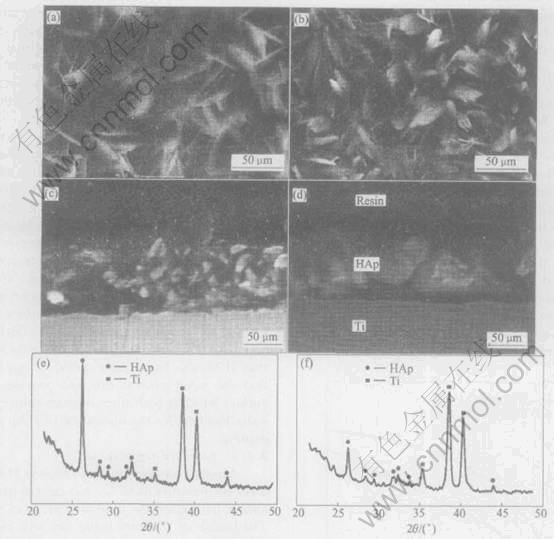
Fig.3 SEM morphologies of top view ((a), (b)) and cross view ((c), (d)) and XRD spectrum ((e), (f)) of samples deposited from 6% H2O2 modified solution at -0.8V ((a), (c), (e)) and traditional solution at -1.6V ((b), (d), (f))
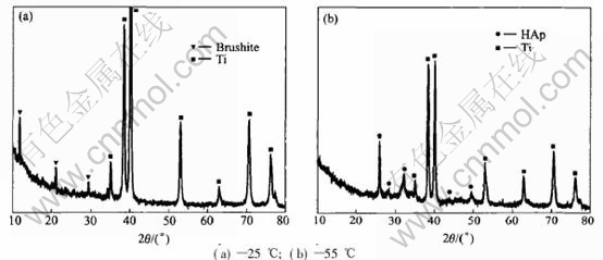
Fig.4 Effect of temperature on crystal structure of coatings
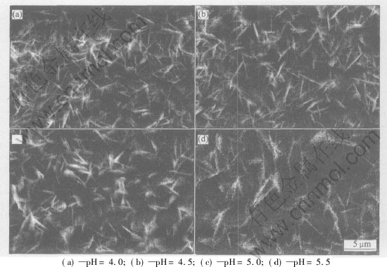
Fig.5 Effect of pH on surface morphology of coatings
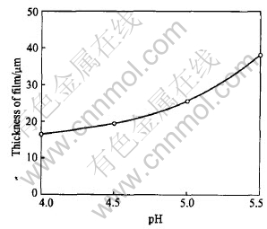
Fig.6 Effect of solution pH on thickness of coatings deposited
4.0 keeps higher through the whole deposition process than that of pH 5.5(Fig.7). Although higher current or larger amount of produced OH- ions per unit time, can be obtained at lower pH, the deposition rate seems to be maintain low. It is plausible that under this condition fairly part of OH- ions has been neutralized by the bulk H+ ions. In the whole process this results in lower local pH as well as super saturation in the close vicinity of electrode. And correspondingly this leads to slower deposition rate and thinner film.
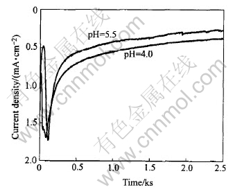
Fig.7 Effect of solution pH on cathodic current density
3.2.3 Effect of deposition potential
Fig.8 shows the SEM images and XRD results of electrode surface after cathodically polarized at -1.2V. Compared with the results in Fig.3 for sample deposited at -0.8V, it can be seen that the potential strongly affect the deposition process. When the potential changes from -0.8 to -1.2V, no crystal can be seen clearly under the same magnification. Besides, crack which reveals the existence of inner strain appears on the surface. White deposits like cloud are dispersed here and there. The growing rate also slows down for the film��s thickness in Fig.8(b) is only 1/3 as that shown in Fig.3(c). This is not surprising because under the intense cathodic polarizing condition, the local pH and super saturation near electrode becomes so high that the precipitation rate will become extremely fast. Then there is not enough time for the ions to diffuse to a certain site to grow into regular crystal. It could be expected that if the driving force for crystallization is high enough, homogeneous precipitation will take place before the Ca2+ and PO3-4 ions can reach the electrode surface by diffusion, which results in a lower film growth rate.
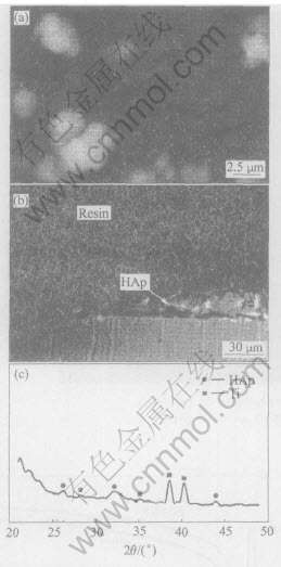
Fig.8 SEM morphologies of top view(a) and cross view(b) and XRD spectrum(c) of sample deposited at -1.6V
The peaks on XRD spectrum sample can be assigned to HAp and titanium, but they are weaker than that of at -0.8V. This informs that the HAp coatings is of lower crystallinity.
4 CONCLUSIONS
A novel process for electrodeposition of hydroxyapatite coating on titanium substrate was developed. Addition of H2O2 to the electrolyte changes the mechanism of the electrochemical reaction on the cathode, and the evolution of H2 gas that obsess deposition from traditional electrolyte is erased. Besides, owing to the high intensity of being reduced on electrode, a fairly high cathodic current can be gained at potential of less than -1.0V. Dense and homogeneous film is crystallized at high rate. At the same time, the mechanism of crystallize process has been discussed.
REFERENCES
[1]Hara T, Hayashi K, Nakashima Y, et al. The effect of hydroxyapatite coating on the bonding of bone to titanium implants in the femora of ovariectomised rats [J]. Journal of Bone and Joint Surgery, 1999, B81(4): 705-709.
[2]Chou L, Marek B, Wagner W R. Effects of hydroxylapatite coating crystallinity on biosolubility, cell attachment efficiency and proliferation in vitro [J]. Biomaterials, 1999, 20(10): 977-985.
[3]Browne M, Gregson P J. Effect of mechanical surface pretreatment on metal ion release [J]. Biomaterials, 2000, 21(4): 385-392.
[4]Feng C F, Khor K A, Liu E J, et al. Phase transformations in plasma sprayed hydroxyapatite coatings [J]. Scripta Materialia, 1999, 42(1): 103-109.
[5]Cheang P A, Khor K L, Teoh L C, et al. Pulsed laser treatment of plasma-sprayed hydroxyapatite coatings [J]. Biomaterials, 1996, 17(19): 1901-1904.
[6]Lopatin C M, Pizziconi V, Alford T L, et al. Hydroxyapatite powders and thin films prepared by a sol-gel technique [J]. Thin Solid Films, 1998, 326(1-2): 227-232.
[7]Zhitomirsky I, Gal-Or L. Electrophoretic deposition of hydroxyapatite [J]. Journal of Materials Science: Materials in Medicine, 1997, 8(4): 213-219.
[8]Redepenning J, McIsaac J P. Electrocrystallization of brushite coatings on prosthetic alloys [J]. Chemistry of Materials, 1990, 2: 625-627.
[9]Shirkhanzadeh M. Bioactive calcium phosphate coatings prepared by electrodeposition [J]. Journal of Material Science Letter, 1991, 10: 1415-1417.
[10]Shirkhanzadeh M. Electrochemical preparation of bioactive calcium phosphate coatings on porous substrates by the periodic pulse technique [J]. Journal of Material Science Letter, 1993, 12: 16-19.
[11]Chen J, Juang H, Hon M. Calcium phosphate coating on titanium substrate by a modified electrocrystalization process [J]. Journal of Material Science: Material in Medicine, 1998, 9: 297-300.
[12]Ban S, Maruno S. Deposition of calcium phosphate on titanium by electrochemical process in simulated body fluid [J]. Japan Journal of Applied Physics, 1993, 32: L1577-580.
[13]Therese G H A, Vishnu-Kamath P, Subbanna G N. Novel electrosynthetic route to calcium phosphate coatings [J]. Journal of Material Chemistry, 1998, 8(2): 405-408.
[14]Yen S. Mechanism of electrolytic ZrO2 coating on commercial pure titanium [J]. Materials Chemistry and Physics, 2000, 63: 256-262.
[15]Mao C, Li H, Cui F, et al. Oriented growth of phosphates on polycrystalline titanium in a process mimicking biomineralization [J]. Journal of Crystal Growth, 1999, 206(4): 308-321.
[16]Shirkhanzadeh M. Direct formation of nanophase hydroxyapatite on cathodically polarized electrodes [J]. Journal of Materials Science: Materials in Medicine, 1998, 9: 967-72.
[17]Monma T. Electrochemical deposition of calcium-deficient apatite on stainless steel substrate [J]. Journal of the Ceramic Society of Japan, 1993, 101(7): 737-739.
(Edited by LONG Huai-zhong)
Foundation item: Project(50104012) supported by the National Natural Science Foundation of China
Received date: 2005-01-21; Accepted date: 2005-09-14
Correspondence: ZHAO Zhong-wei, Professor, PhD; Tel: +86-24-8830477; E-mail: zhaozw@mail.csu.edu.cn
