
J. Cent. South Univ. (2017) 24: 1322-1343
DOI: 10.1007/s11771-017-3537-2

Performance analysis and design of MIMO-OFDM system using concatenated forward error correction codes
Arun Agarwal1, Saurabh N. Mehta2
1. PhD Scholar, School of Electrical Engineering, Department of Information Technology, AMET University,Tamil Nadu, Chennai 603112, India;
2. Department of Electronics and Telecommunication Engineering, Vidyalankar Institute of Technology, Mumbai-400037, Maharashtra, India
 Central South University Press and Springer-Verlag Berlin Heidelberg 2017
Abstract:
This work investigates the performance of various forward error correction codes, by which the MIMO-OFDM system is deployed. To ensure fair investigation, the performance of four modulations, namely, binary phase shift keying (BPSK), quadrature phase shift keying (QPSK), quadrature amplitude modulation (QAM)-16 and QAM-64 with four error correction codes (convolutional code (CC), Reed-Solomon code (RSC)+CC, low density parity check (LDPC)+CC, Turbo+CC) is studied under three channel models (additive white Guassian noise (AWGN), Rayleigh, Rician) and three different antenna configurations(2��2, 2��4, 4��4). The bit error rate (BER) and the peak signal to noise ratio (PSNR) are taken as the measures of performance. The binary data and the color image data are transmitted and the graphs are plotted for various modulations with different channels and error correction codes. Analysis on the performance measures confirm that the Turbo + CC code in 4��4 configurations exhibits better performance.
Key words:
1 Introduction
In recent years, MIMO (multiple input multiple output) has developed and emerged as a very important technology in wireless communications [1-9]. MIMO supports multiple transmission purposes through exploiting its unique properties, such as the spatial diversity gain and the properties that are related to the spatial multiplexing capability [10]. The MIMO system has the advantages of wide bandwidth, good isolation, enhanced radiation with low correlation [2] and bandwidth efficiency [10]. Orthogonal frequency division multiplexing (OFDM) is one of the most powerful modulation techniques that is employed in networking [10-15]. Plenty of designs have been introduced and the generated codes have varied multiplexing and diversity gains [4]. The merits of OFDM include high robustness to linear fiber effects, sharp roll-off of OFDM spectrum, multiple access capabilities and tolerance to inter-symbol interference and inter-carrier interference [13]. MIMO systems consume less extra spectrum because of the development of space�Ctime (ST) coding [10]. In addition, the MIMO technology provides a quality system to enhance the signal reliability as well as the multiple transmissions, without extra radiation and spectrum bandwidth [6-9]. OFDM is a technique for high-rate wireless transmission systems because of its high spectral efficiency, immunity against inter-symbol interference and robustness against multi-path channel fading. It also provides frequency diversity and thereby, it improves the BER performance of the frequency selective fading channels [16-22]. The combination of MIMO wireless technology with OFDM has been recognized as a most promising technique [23]. The combined MIMO-OFDM technique has advantages such as, increased spectral efficiency of OFDM [24] and improved link reliability that enables the support of more antennas and larger bandwidths, leading to high data rate as well as high performance and it has larger utilization in high-speed wireless transmission [25]. The increase in the transmission bandwidth efficiency of the combined MIMO-OFDM has been studied through estimating the blind channel of the system [26]. The combined MIMO system (Alamouti space-time block coding (STBC) MIMO system within space division multiplexing (SDM)) has been analyzed and studied through considering the matrix structure, which is present in the equivalent channel matrix H of Ref. [5]. For the reliable transmission of signals through the MIMO system,STBC has been developed. The STBC transmission using the combined SDM and STBC has been well- analyzed and it was found to be useful for the evaluation of other MIMO transmissions with quasiorthogonal STBC [1]. The XPM-induced degradation in each subcarrier of the double sideband-OFDM (DSB-OFDM) systems that employ a DD receiver has been analytically characterized in Ref. [13]. An innovative method has been developed to reduce the complexity and peak to average power ratio of T-OFDM systems in Ref. [12]. The DCP-OQAM-OFDM and the ECP-OQAM-OFDM systems have been analyzed and their power spectral densities have also been studied in Ref. [11]. Generally, the error-correcting codes produce a threshold effect that gradually reduces the performance at the low signal to noise ratio (SNR) range. So, in order to minimize the threshold effect, two types of error correction codes that are related to the chaotic dynamical systems [27] have been introduced. One of the error correction codes is based on the principles of diversity and the other one is based on the LDPC code. LDPC was introduced by GALLAGER [28] in 1962 and was rediscovered by Mackay and NEAL [29] in 1996. The LDPC code exhibits a very low threshold effect. Orthogonal space time block codes (OSTBC) is used, in the case of the transmitting antennas [30]. It exhibits the property of diversity, but there is no coding gain. Hence, OSTBC that is concatenated with MIMO-OFDM [31, 32] has been used to provide diversity in both space and time. The concatenation scheme includes an inner OSTBC code and an outer channel code. The BER performance of the OSTBC code with MIMO-OFDM has been evaluated by not concatenating with the channel codes of [33-36]. Convolution code is a channel coding technique, which is concatenated with Alamouti STBC under various fading conditions that include uncorrelated fading and spatial correlated as well as spatial time correlated fading [33]. The efficiency of the convolution coded MIMO-OFDM systems has been analyzed without the correlation channel models [37]. The block diagram of MIMO-OFDM system with the forward error correction representation is shown in Fig. 1. Forward error correction (FEC) applies on the communication over wireless and it has been used as a technique for controlling as well as correcting the errors that are produced during video distribution. FEC codes include the recursive systematic convolution code and the Turbo code. While using MIMO system, an inter-layer FEC coding technique that is combined with UEP is applied [38]. The concatenated error correction code scheme, termed as LDPC with Alamouti code MIMO-OFDM, has been analyzed under various fading conditions, such as spatially independent, spatially correlated, spatial temporal correlated and spatial time frequency correlated quasi-static Rayleigh, Rician and Nakagami fading channels. Due to the correlation structure, the loss of diversity and the coding gain emerges. The arrangement of concatenated code has been achieved by considering all the individual blocks [26].
This work presents a systematic study on the performance of the MIMO-OFDM system with concatenated forward error correction codes. Firstly, an MIMO-OFDM system is constructed with the convolutional codes as the error correction codes and the concatenation of the convolutional codes with the renowned block codes, such as LDPC codes, RSC and Turbo codes then follows.
Secondly, the systems are tested by transmitting one-dimensional binary data and the BER analysis is performed. Subsequently, image transmission is also performed on these systems and the PSNR analysis is carried out.
2 Concatenated FEC codes for MIMO- OFDM system
2.1 Without concatenation of FEC codes
Prior to the description of the concatenated FEC codes for the MIMO OFDM system, the MIMO OFDM system with convolutional codes alone (i.e., without concatenating multiple FECs) is presented. BIGDELI and ABOLHASSANI [39] have proposed a method for deriving an exact closed-form transfer function (TF) for the convolutional code. LIU et al [40] have developed a two-relay full-duplex asynchronous cooperative network with the amplify-and-forward (AF) protocol and convolutional space-time coding. A three-layer decoding framework for the asynchronous convolutional-coded PNC systems has been developed by YANG and LIEW [41].
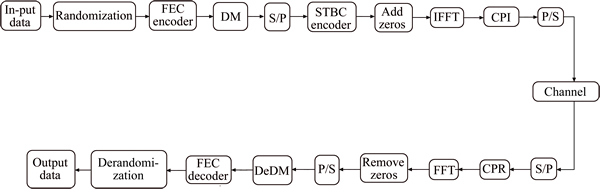
Fig. 1 High-level architecture of MIMO-OFDM system with forward error correction codes
2.2 Concatenation of LDPC codes with convolutional codes
GROSJEAN et al [42] have developed the non-terminated systemic photograph-based LDPC, which was concatenated with the convolutional code that contained high memory for achieving anytime reliability in an asymptotic way. The bilayer LDPC convolutional codes have been developed by SI et al [43] for three- node relay channels.
2.3 Concatenation of RSC with convolutional codes
CHEN [44] has developed a novel iterative soft decoding algorithm for the RSC concatenated convolutional code, aiming to better exploit its error correction potential. NGO et al [45] have proposed the non-coherently detected Reed-Solomon coded and slow frequency hopping (SFH)-assisted M-array frequency shift keying for the cooperative wireless networks.
2.4 Concatenation of Turbo codes with convolutional codes
KAYA and OZTURK [46] have proposed a new distributed Turbo coded (DTC) scheme, which used two best relays that were selected among multi-relays. The double binary convolutional Turbo code was applied to the 21451-5 sensor and the actuator networks and a low-complexity decoding solution has been proposed for the iterative decoding by ZHAN et al [47].
3 Error rate analysis
3.1 Experimental setup
The MIMO-OFDM system with various concatenations of FEC codes is simulated in MATLAB and the BER is observed for varying SNR. The systems are separately studied under the AWGN environment, the Rayleigh channel and the Rician channel. The experimentation is extended by considering the four renowned modulation schemes, namely, BPSK, QPSK, QAM16 and QAM64.
3.2 Effect of AWGN environment
AWGN is one of the noise models that often corrupt the signal, while it travels in the deep space communication links. The characteristic features of this model include frequency selectivity, unfading, interference and nonlinearity.Interference may result in some cases, so it is not a good model for the terrestrial links [4]. The effect of AWGN on the concatenated error correction codes is investigated here. Simulation results are plotted for BPSK, QPSK, QAM-16 and QAM-64 system, in terms of BER with variation in the SNR ratio, as shown in Figs. 2-5, respectively. In Fig. 2, at 10 dB SNR, the BER is monotonically reduced to 0.04, 0.03 and 0.02 for CC code, 0.03, 0.02 and 0.008 for RSC+CC, 0.02, 0.008 and 0.004 for LDPC+CC and 0.02, 0.004 and 10-3 for Turbo code in 2��2, 2��4 and 4��4 configurations, respectively. The 4��4, 2��4 and 2��2 plot reach the BER of 10-1 for CC at 7 dB, 8 dB and 9 dB SNR, for RSC+CC at 6 dB, 7 dB and 8 dB SNR, for LDPC+CC at 5 dB, 6 dB and 6 dB SNR, respectively. In CC, the 4��4 slope is smaller than the other slopes and the noise enhancement is found to be nil. When the SNR level changes from 1 to 2 dB, the symbols overlap each other. When RSC is combined with CC, the 4��4 plot reaches 10-2 BER only. When LDPC is combined with CC, the 2��4 as well as the 4x4 plots reaches the 10-2 BER at an SNR of 10 dB. When the Turbo code is combined with CC, the 4��4, 2��4 and 2��2 plots reach the BER of 10-2 at an SNR of 8 dB, 9 dB and 10 dB, respectively. Only 4��4 plots reach the 10-3 BER. The noise enhancement is high among these plots. The slope is more for the 4��4 antenna configuration and there is no symbol overlapping. The 2��2 plot fails to reach 10-3 BER. In Fig. 3, at 10 dB SNR, the BER reduces to 0.03, 10-2 and 0.008 for CC code, 0.01, 0.004 and 10-3 for RSC+CC, 0.004, 0.0003 and 0.0003 for Turbo code in 2��2, 2��4 and 4��4 configurations, respectively. The 4��4, 2��4 and 2��2 plots reach the BER of 10-1 for CC at 6 dB, 7 dB and 8 dB SNR, for LDPC+CC at 10-4, 10-3, 10-2 SNR, respectively. In CC, the 4��4 plot reaches the BER of 10-2 only. In RSC+CC, the 4��4 plot reaches the BER of 10-3. The noise enhancement level is found to be more between the 2��4 and the 2��2 plots. The 4��4 as well as the 2��4 plots reaches the BER of 10-2 at an SNR of 8 dB and 9 dB, in a respective fashion. When LDPC is concatenated with CC, the BER reduces to 0.002 and 0.0002 at an SNR of about 10 dB for the 2��4 and 4��4 plots, respectively. The 4��4 plot reaches the BER of 10-4 only. The noise enhancement level is found to be more between the 4��4 and the 2��4 plots. In Fig. 4, at 10 dB SNR, the BER reduces to 0.004, 0.004 and 10-3 for CC code, 0.004, 0.0003 and 0.00003 for RSC+CC, 10-5, 10-6 for LDPC+CC and 10-6, 10-6 and 10-8 for Turbo code in 2��2, 2��4 and 4��4 configurations, respectively. The 4��4, 2��4 and 2��2 plot reaches the BER of 10-2 for CC at 8 dB, 9 dB and 10 dB SNR, respectively. In CC, the 4��4 plot reaches the BER of 10-3. When RSC +CC is used, the 4��4 plot reaches the BER of 10-2. The noise enhancement level is more between the 4��4 and the 2��4 plots. In LDPC+CC, the 4��4 plot reaches the BER of 10-2. The noise enhancement level is found to be more between the 2��2 and the 2��4 plots. In Turbo code, the noise enhancement level is found to be more between the 2��2 and the 2��4 plots. The Turbo concatenated with CC offers better performance in reducing the noise level of an AWGN environment with all modulation system. In Fig. 5, at 10 dB SNR, the BER is monotonically reduced to 10-2, 0.004 and 10-3for CC code, 0.004, 0.0003 and 0.00003 for RSC+CC, 10-3, 10-5 and 10-6 for LDPC+CC and 10-4, 10-6 and 10-8 for Turbo code in 2��2, 2��4 and 4��4 configurations, respectively. The 4��4, 2��4 and 2��2 plots reach the BER of 10-1 for CC at 8 dB, 9 dB and 10 dB SNR, respectively.
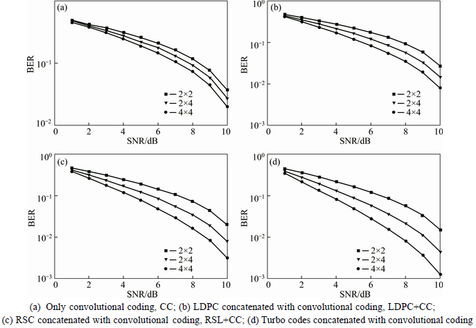
Fig. 2 BER analysis of MIMO-OFDM system with BPSK modulation and FEC schemes in AWGN environment:
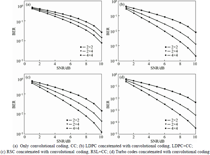
Fig. 3 BER analysis of MIMO-OFDM system with QPSK modulation and FEC schemes in AWGN environment:
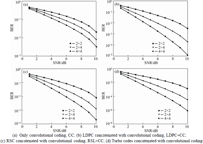
Fig. 4 BER analysis of MIMO-OFDM system with QAM-16 modulation and FEC schemes in AWGN environment:
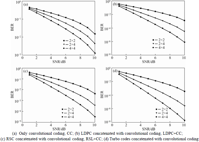
Fig. 5 BER analysis of MIMO-OFDM system with QAM-64 modulation and FEC schemes in AWGN environment:
3.3 Effect of Rayleigh channel
Rayleigh fading channel is a channel model for signal propagation in troposphere and ionosphere. It often occurs when there is no line of sight between the transmitter and the receiver. It is caused by multipath reception [6]. The BER and the error intensity of the time varying Rayleigh fading channels are analyzed by the selection combining method of the received signals, which are at the destination of a D-AF relay network that employs DBPSK [40]. Simulation results for the BPSK, QPSK, QAM-16 and QAM-64 systems under Rayleigh channel are plotted, in terms of BER with variation in SNR ratio, as portrayed in Figs. 6-9, respectively. In Fig. 6, at 10 dB SNR, the BER reduces to 0.03, 0.04 and 0.04 for RSC+CC, 0.04, 0.04 and 0.03 for LDPC+CC in 2��2, 2��4 and 4��4 configurations, respectively. The 4��4, 2��4 and 2��2 plots reach the BER of 10-1 for Turbo+CC at 8 dB, 9 dB and 9 dB, respectively. For CC, all plots show reduction in BER to about 0.04 at an SNR of about 10 dB. The same BER performance results are obtained because they have the same structures with difference in the input data symbols or the truncation of the transmitting signal. The symbols seem to overlap and so, the Rayleigh fading-based channel in CC code can achieve more multipath diversity gain. When comparing the three plots in RSC+CC, the error rate variation among them is found to be very less. In LDPC+CC, the symbols are noted to overlap each other until 3 dB, which indicate that there is a lot of interference. At an SNR of about 9 dB, the three plots reach 10-1 BER. When the Turbo code is combined with CC, the BER reduces to 0.03 and 0.04 at an SNR of about 10 dB in 2��4 and 4��4 plots, respectively. In Fig. 7, at 10 dB SNR, the BER reduces to 0.04, 0.03 and 0.03 for RSC+CC, 0.04, 0.03 and 0.02 for LDPC+CC and 0.04, 0.03 and 0.02 for Turbo code in 2��2, 2��4 and 4��4 configurations, respectively. The 4��4, 2��4 and 2��2 plots reach the BER of 10-1 for CC at 7 dB, 8 dB and 9 dB SNR, for RSC+CC at 8 dB, 9 dB and 9 dB SNR, for LDPC+CC at 8 dB, 8 dB and 9 dB SNR, for Turbo at 7 dB, 8 dB and 9 dB SNR, respectively. When CC is used, the BER reduces to 0.03 and 0.04 at an SNR of about 10 dB in 2��4 and 4��4 plots, respectively. The noise enhancement level is found to be the same for all the codes.
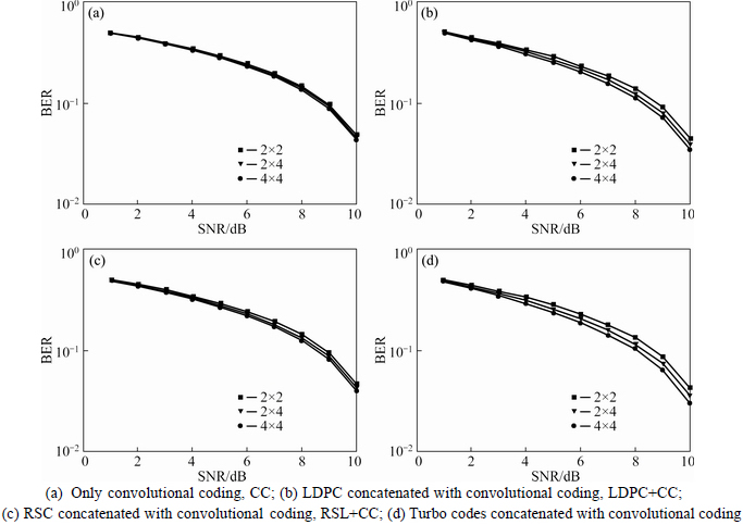
Fig. 6 BER analysis of MIMO-OFDM system with BPSK modulation and FEC schemes in Rayleigh environment:

Fig. 7 BER analysis of MIMO-OFDM system with QPSK modulation and FEC schemes in Rayleigh environment:
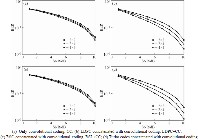
Fig. 8 BER analysis of MIMO-OFDM system with QAM-16 modulation and FEC schemes in Rayleigh environment:
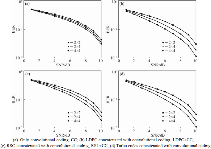
Fig. 9 BER analysis of MIMO-OFDM system with QAM-64 modulation and FEC schemes in Rayleigh environment:
The three sub plots are found to overlap at 2 dB and 3 dB. The noise enhancement level is found to be more or less same between the plots in RSC+CC and LDPC+CC.
For the Turbo code, the 4��4 plot is more adjacent to the BER of 10-2 and there is less noise interference in 4��4 configurations.
In Fig. 8, at 10 dB SNR, the BER reduces to 0.04, 0.04 and 0.03 for CC code, 0.04, 0.03 and 0.02 for RSC+CC, 0.03, 0.02 and 10-2 for LDPC+CC and 0.03, 0.02 and 10-2 for Turbo code in 2��2, 2��4 and 4��4 configurations, respectively. The 4��4, 2��4 and 2��2 plots reach the BER of 10-1 for CC at 7 dB, 8 dB and 9 dB SNR, for RSC+CC at 8 dB, 8 dB and 9 dB SNR, for LDPC+CC at 7 dB, 8 dB and 8 dB SNR, for Turbo+CC at 6 dB, 7 dB and 8 dB SNR, respectively. The 4��4 plot reaches the BER of 10-2 only. The symbols tend to overlap in this case. All the plots are very close to each other and very little noise variation is found between the plots. In LDPC+CC, the 4��4 plot reaches the BER of 10-2. In Turbo concatenation, the noise enhancement level is found to be the same. In Fig. 9, at 10 dB SNR, the BER is reduced to 0.03, 0.03 and 0.03 for CC code, 0.03, 0.02 and 0.02 for RSC+CC, 0.03, 0.02 and 10-2 for LDPC+CC and 0.02, 10-2 and 0.07 for Turbo code in 2��2, 2��4 and 4��4 configurations, respectively. The 4��4, 2��4 and 2��2 plot has reached the BER of 10-1 for CC at 8 dB, 8 dB and 8 dB SNR, for RSC+CC at 7 dB, 8 dB and 8 dB SNR, for LDPC+CC at 6 dB, 7 dB and 8 dB SNR for Turbo at 5 dB, 6 dB and 8 dB SNR, respectively. In CC, the estimated errors of all the cases decrease with the increase in SNR and the noise enhancement level is found to be the same between the configurations. While comparing the four channel codes, the turbo concatenated with CC exhibits the better performance in reducing the noise level of the Rayleigh environment with all types of modulation systems.
3.4 Effect of Rician channel
Rician fading model is a type of channel model for signal propagation with a strong dominant component. The stationary component is a non fading channel, called as the line of sight component [6]. Simulation results are plotted, in terms of BER with variation in SNR ratio, for BPSK, QPSK, QAM-16 and QAM-64 systems under the Rician environment as shown in Figs.10-13,respectively. In Fig. 10, at 10 dB SNR, the BER is reduced to 0.04, 0.04 and 0.03 for CC code, 0.04, 0.03 and 0.02 for RSC+CC, 0.04, 0.03 and 0.02 for LDPC+ CC and 0.03, 0.02 and 10-2 for Turbo code in 2��2, 2��4 and 4��4 configurations, respectively. The 4��4, 2��4 and 2��2 plots reach the BER of 10-1 for LDPC+CC at 7 dB, 8 dB and 9 dB SNR, respectively. The symbols overlap at 2 dB and the noise enhancement level variation is found to be very less for the three configurations of the CC code. The 4��4 plot shows more slopes and its noise enhancement level is found to be the same, when compared with the other two plots of RSC+CC. When Turbo code is combined with CC, the noise enhancement level is found to be more between the 4��4 and the 2��4 plots. In Fig. 11, at 10 dB SNR, the BER reduces to 0.04, 0.03 and 0.02 for CC code, 0.03, 0.02 and 10-2 for RSC+CC, 0.03, 10-2 and 0.006 for LDPC+CC and 0.02, 0.008 and 0.003 for Turbo code in 2��2, 2��4 and 4��4 configurations, respectively. The 4��4, 2��4 and 2��2 plots reach the BER of 10-1 for CC at 8 dB, 8 dB and 9 dB SNR, for RSC+CC at 6 dB, 7 dB and 8 dB SNR, respectively. When LDPC is combined with CC, the noise enhancement level is found to be more between the 2��2 and 2��4 plots, when compared with the 4��4 and 2��4 plots, and the slope is more for the 4��4 configured plots. In Fig. 12, at 10 dB SNR, the BER reduces to 0.03, 0.02 and 10-2 for CC code, 10-2, 10-2 and 0.007 for RSC+CC, 0.02, 0.006 and 0.002 for LDPC+CC and 10-2, 0.003 and 0.0009 for Turbo code in 2��2, 2��4 and 4��4 configurations, respectively. The 4��4, 2��4 and 2��2 plots reach the BER of 10-1 for CC at 7 dB, 8 dB and 8 dB SNR, respectively. In Fig. 13, at 10 dB SNR, the BER reduces to 0.03, 0.02 and 10-2 for CC code, 0.02, 0.008 and 0.003 for RSC+CC, 10-2, 0.03 and 0.0009 for LDPC+CC and 0.008, 10-3 and 0.0002 for Turbo code in 2��2, 2��4 and 4��4 configurations, respectively. The 4��4, 2��4 and 2��2 plots reach the BER of 10-1 for CC at 8 dB, 7 dB and 6 dB SNR, respectively. In Turbo concatenated with CC, the noise enhancement level is found to be more between the 4��4 and 2��4 plots. The 4��4, 2��4 and 2��2 plots reach the BER of 10-4, 10-3, 10-2, respectively, at an SNR of 10 dB. The turbo concatenated with CC shows better performance in reducing the noise level of the Rician environment with all modulation systems.

Fig. 10 BER analysis of MIMO-OFDM system with BPSK modulation and FEC schemes in Rician environment:
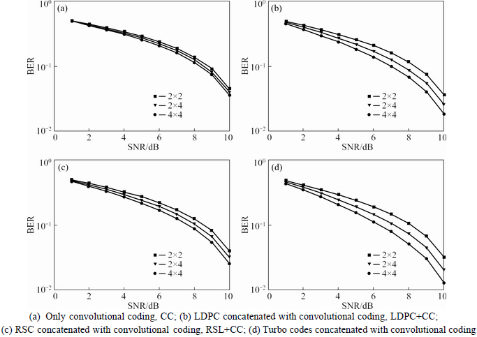
Fig. 11 BER analysis of MIMO-OFDM system with QPSK modulation and FEC schemes in Rician environment:
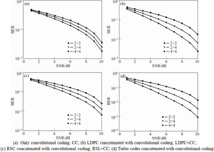
Fig. 12 BER analysis of MIMO-OFDM system with QAM-16 modulation and FEC schemes in Rician environment:
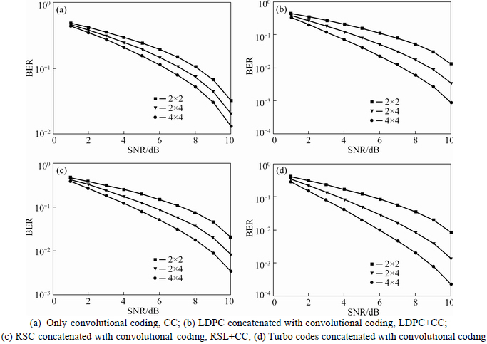
Fig. 13 BER analysis of MIMO-OFDM system with QAM-64 modulation and FEC schemes in Rician environment:
4 PSNR analysis on image transmission
4.1 Procedure
With the similar experimental setup, a color image is transmitted through the MIMO-OFDM system. Since the color image is a three-dimensional matrix, one- dimensional data are constructed from the color image, prior to transmission. The PSNR is determined for the received image and the results are illustrated.
4.2 Effect of AWGN environment
AWGN is a widely used channel model in wireless communications. In the MIMO-OFDM system, the communication under AWGN environment is done by developing many algorithms and the performance is measured using the PSNR. Simulation results are plotted, in terms of PSNR with variation in SNR ratio, for BPSK, QPSK, QAM-16, QAM-64 modulations in the AWGN channel mode for various error correction codes with three antenna configurations as shown in Figs. 14-17, respectively. In Fig. 14, at an SNR of 10 dB, the deviation difference between 2��2, 2��4 and 2��4, 4��4 curves are found to be 80% and 31% for RSC+CC, 38% at 8 dB and 37% at 10 dB for LDPC+CC. When using CC, the 4��4 curve shows increased PSNR for an SNR of about 10 dB. The 2��4 curve has tilted when it reached a SNR of about 9 dB. In RSC+CC, the 2��4 curve seems to be linear in nature. In the case of the 4��4 curves, the deviation has become more at an SNR of 10 dB. The deviation is found to be more at 8-10 dB in 2��2 curves.When LDPC+CC is used, the 4��4 curve reaches the SNR of 8 dB. The 2��4 curve has a steep slope in the SNR range of 9-10 dB. More deviational difference is seen between the 2��4 and the 2��2 curves, when the SNR assumed values between 7 db and 9 dB. When Turbo+ CC is used, the 4��4 curve shows a steep slope up to a PSNR of 25. However, for the 2��4 curves at a PSNR of 2, the curve bends and causes the PSNR value to get reduced. The 2��2 curve shows a linear form. The peak deviation becomes more at 8 dB for the 2��4 curves. The deviation between the 2��2 curve and the 2��4 curve is found to be 110% at 8 dB.In Fig. 15, the deviation between 2��2, 2��4 and 2��4, 4��4 curves is found to be 44% and 75% at 10 dB for CC, 100% and 280% at 9 dB for RSC+CC, 40% and 400% at 5 dB for LDPC+CC. In CC code, the 2��2 curve exhibits a linear nature.
In the case of the 4��4 curve, a steep increase from 9-10 dB that reaches the PSNR of -1 is experienced. When the RSC +CC code is used, the 4��4 curve shows a steep increase at 6-7 dB. The 2��2 curve reaches the SNR level of 10 dB. For the LDPC+CC code, a steep increase in the 4��4 curve is seen at an SNR of 4-5 dB, 6-7 dB, 8-9 dB and then, a dwindling occurs. While using Turbo +CC code, the 4��4 plot shows a straight line.
The 2��4 curve tends to curve slightly with a little increase in the slope. The deviation between the 2��4 curve and the 2��2 curve is found to be 150% at an SNR of 5 dB.
In Fig. 16, the deviation difference between 2��2 as well as 2��4 curves and 2��4 as well as 4��4 curves is found to be 36% and 42% at 8 dB, 48% and 38% at 5 dB for RSC+CC, 48% and 330% at 7 dB for LDPC+CC.
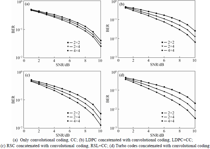
Fig. 14 PSNR analysis of MIMO-OFDM system with BPSK modulation and FEC schemes in AWGN environment:

Fig. 15 PSNR analysis of MIMO-OFDM system with QPSK modulation and FEC schemes in AWGN environment:
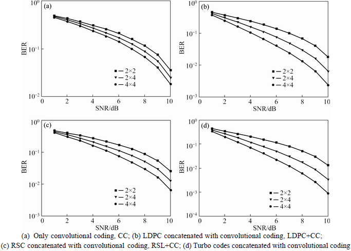
Fig. 16 PSNR analysis of MIMO-OFDM system with QAM-16 modulation and FEC schemes in AWGN environment:

Fig. 17 PSNR analysis of MIMO-OFDM system with QAM-64 modulation and FEC schemes in AWGN environment:
When CC code is used, the 4��4 curve shows increased PSNR value. The three curves differ from each other. The 4��4 curve bends slightly after reaching 7 dB and deviation between 2��2 and 2��4 is more from 8-10 dB. In RSC+CC, the 2��2 curve shows fewer slopes. The 2��4 curve shows a steep rise from 6-7 dB.
In Fig. 17, when CC code is used, the 2��2 curve shows an increase from 9-10 dB SNR and the 2��4 curve increases at 8-9 dB. The 4��4 curve shows a sharp rise from 6-7 dB SNR. In RSC+CC code, the 4��4 curve shows a straight line. The 2��2 curve reaches a peak at 7 dB and bends to 8 and has a sharp peak at 9 dB SNR with PSNR of 18. The deviation between 2��2, 2��4 curves is found to be 125% at an SNR of 5 dB. When LDPC is combined with CC code, the three plots 4��4, 2��4, 2��2 show a straight line reaching at 2, 3 and 6 dB respectively.
But in Turbo+CC code, the 4��4 seems to be a small point at 1 dB SNR with -18 PSNR. The 2��4 is a straight line at 2 dB SNR with -16 PSNR. The 2��2 is a normal curve at 5 dB SNR with 0 PSNR.
The turbo concatenated with CC is found to have a better performance in reducing the noise level of the AWGN environment using four types of modulations.
4.3 Effect of Rayleigh channel
Rayleigh channel is mostly caused by multiple path rejection. Simulation results are plotted, in terms of PSNR with variation in SNR ratio, for BPSK, QPSK, QAM-16 and QAM-64 systems as shown in Figs. 18-21, respectively. In Fig. 14, at an SNR of 10 dB, the deviation difference between the 2��2 as well as the 2��4 curve and the 2��4 as well as the 4��4 curves is found to be 10% and 4% for CC, 14% and 25% for RSC+CC, 38% and 15% and 18% at 10 dB for LDPC+CC and 24% and 47% for Turbo code. In CC code, the symbols tend to overlap each other at an SNR of 1 dB and 2 dB with a PSNR of -39 and -38. When using the RSC+CC code, at an SNR of about 1 dB with a PSNR of -38, the 2��2 curve and the 2��4 curve overlap each other. So, there is no deviation between them. Deviation is more between the 2��2 and 2��4 curves at 7-10 dB. In LDPC+CC code, the 2��2 curves show more slope. The deviation is more at an SNR of about 10 dB. At an SNR of 1 dB with a PSNR of -38, the deviation is less and the symbols are found to overlap each other in the Turbo concatenated code. The 4��4 curve reaches the PSNR of -9 at an SNR of about 10 dB.
In Fig. 19, the deviation difference between the 2��2 as well as the 2��4 curve and the 2��4 as well as the 4��4 curve is found to be 3% and 15% at 10 dB for CC, 16% and 33% at 10 dB for RSC+CC, 28% and 44% for LDPC+CC at 9 dB SNR, 56% and 61% at 9 dB for Turbo code. In Turbo +CC code, the three curves show high deviation differences. The 2��2 curve and 2��4 curve have high deviation than the other two comparisons. The 4��4 curve shows a sharp increase from 6-7 dB. When using CC code, the three curves show similarity with small deviational changes. When combining RSC+CC code, the 4��4 curve shows more deviation at an SNR of 8 dB. In LDPC+CC code, the 2��2, 2��4 and 4��4 curves show less deviation between them and all those curves are similar in nature. In Fig. 20, the deviation difference between the 2��2 curve and the 2��4 curve as well as the 2��4 curve and the 4��4 curve is found to be 36% and 31% at 10 dB for CC, 55% and 100% at 10 dB for RSC+CC, 280% and 100% at 7 dB for LDPC+CC, 60% and 80% at 10 dB SNR for Turbo-concatenated code. In CC code, the three plots show similarity with less deviation differences. But in RSC+CC code, the three curves show similarity with medium deviation differences and in LDPC+CC code, the three curves show similarity with high deviation differences between the 4��4 curve and the 2��4 curve. For the Turbo+CC code, the 4��4 curve shows a straight line. The 2��4 curve and the 2��2 curve show more deviations. At an SNR of 9-10 dB, the 2��2 curve shows a sharp increase in PSNR. The three plots are similar with high deviation differences between the 4��4 curve and the 2��4 curve. In Fig. 21, the deviation difference between the 2��2 curve and the 2��4 curve as well as the 2��4 curve and the 4��4 curve is found to be 25% and 27% at 10 dB for CC, 45% and 84% at 10 dB for RSC+CC, 34% and 46% for LDPC+CC at 8 dB SNR, 37% and 100% at 7 dB for Turbo code. In CC code, the 4��4 curve has increased PSNR, when compared to 2��4 and 2��2 curves at an SNR of about 10 dB. The three curves are found to be similar with small deviation and in RSC+CC code, the 4��4 curve increases at 8-9 dB and slowly bends later on. The 2��4 curve increases at an SNR of 9-10 dB. When using LDPC+CC code, the 4��4 curve shows increased PSNR, when compared to 2��4 and 2��2 curves at an SNR of about 10 dB. The three curves show high deviation between them. When using Turbo+CC code, the 4��4 curve is a sloped straight line curve. Among the four channel codes considered, the Turbo concatenated with CC has a better performance in reducing the noise level of the Rayleigh environment with all four types of modulations.
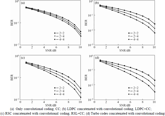
Fig. 18 PSNR analysis of MIMO-OFDM system with BPSK modulation and FEC schemes in Rayleigh environment:
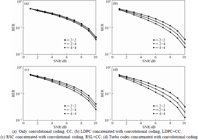
Fig. 19 PSNR analysis of MIMO-OFDM system with QPSK modulation and FEC schemes in Rayleigh environment:
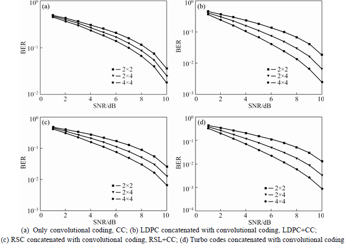
Fig. 20 PSNR analysis of MIMO-OFDM system with QAM-16 modulation and FEC schemes in Rayleigh environment:

Fig. 21 PSNR analysis of MIMO-OFDM system with QAM-64 modulation and FEC schemes in Rayleigh environment:
4.4 Effect of Rician channel
Rician fading model is used for signal transmission with a strong dominant component. Simulation results are plotted, in terms of PSNR with variation in SNR ratio, for BPSK system, QPSK system, QAM-16 and QAM-64 as shown in Figs. 22-25, respectively. In Fig. 22, with CC code at an SNR of about 1 dB, the 2��4 curve and the 4��4 curve overlap each other and so, the deviation is nil. At about 8 dB, the deviation tends to increase between the curves. The three curves move in the same manner. At an SNR of 10 dB, the deviation between the 2��2 curve and the 2��4 curve as well as the 2��4 curve and the 4��4 curve is found to be 10% and 7% for CC, 11% and 21% for RSC+CC, 25% and 22% for LDPC+CC, 45% and 141% for Turbo code. When using RSC+CC code, the 4��4 curves�� deviation is high at an SNR of 8 dB. The deviation is found to be more at 8 dB (about 14%) between the 4��4 and the 2��4 curves. In LDPC+CC code, the symbols do not overlap. The three curves are distinct with unique features. The 4��4 curve shows a steep rise at an SNR of 6dB and gradually moves to 10 dB. The 2��2 curve is linear in nature. With Turbo +CC code, the 4��4 curve shows a slow linearity up to 8 dB, straightens up to 9 dB and steeps at 10 dB finally. The 2��2 curve and the 2��4 curve seem to be a normal curve.
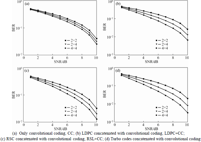
Fig. 22 PSNR analysis of MIMO-OFDM system with BPSK modulation and FEC schemes in Rician environment:
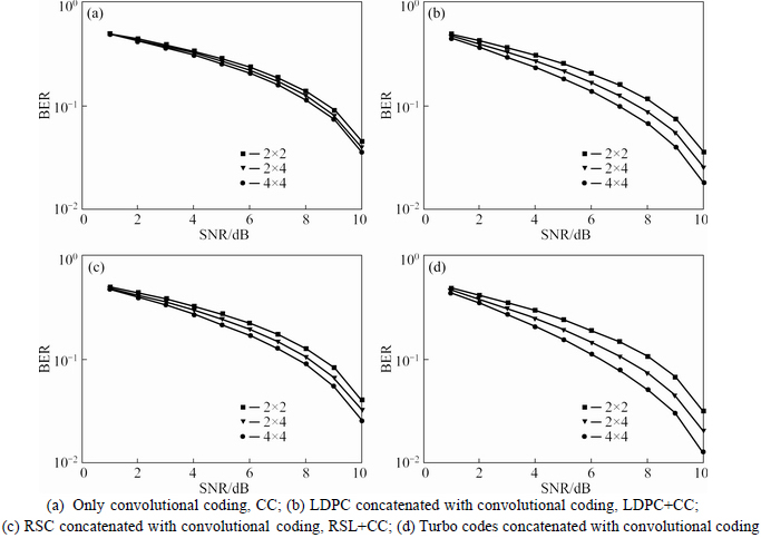
Fig. 23 PSNR analysis of MIMO-OFDM system with QPSK modulation and FEC schemes in Rician environment:
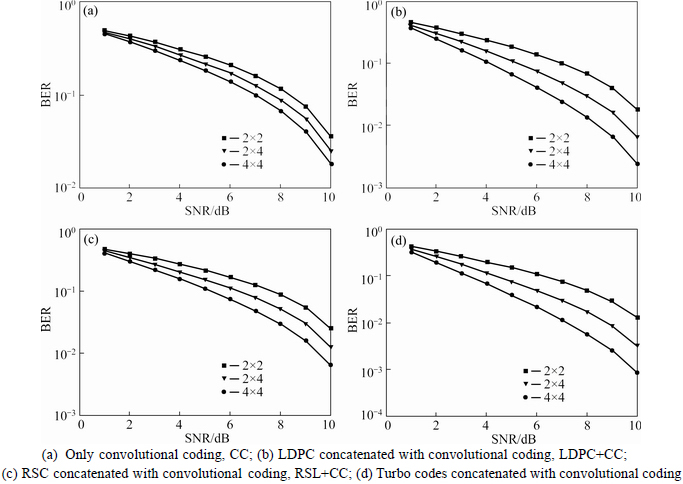
Fig. 24 PSNR analysis of MIMO-OFDM system with QAM-16 modulation and FEC schemes in Rician environment:
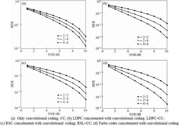
Fig. 25 PSNR analysis of MIMO-OFDM system with QAM-64 modulation and FEC schemes in Rician environment:
In Fig. 23, at an SNR of 10 dB, the deviation between the 2��2 curve and the 2��4 curve as well as the 2��4 curve and the 4��4 curve is found to be 14% and 21% for CC, 50% and 250% for RSC+CC, 60% and 45% for Turbo code and 40% and 220% for LDPC+CC at 8 dB SNR. When using CC code, the 4��4 curve has increased PSNR, when compared to 2��4 and 2��2 curves at an SNR of about 10 dB. The three curves show similar nature with minimal deviation. The deviation is found to be more between the 4��4 and 2��4 curves for CC and RSC+CC at 6-8 dB. With RSC+CC code, the 4��4 curve tends to increase from 8 dB to 10 dB. The 2��2 curve is a linear straight curve. The 4��4 curve has increased PSNR, when compared to 2��4 and 2��2 curves at an SNR of about 10 dB.When using LDPC+CC code, the three plots differ from each other. The 2��2 curve is a linear curve. The 2��4 curve increases at an SNR of 8-9 dB and bends at 9-10 dB. The 4��4 curve shows a sharp narrow increase from 6 dB to 8 dB SNR. When combined Turbo +CC code is used, the 2��2 curve slopes in some places. The 2��4 curve increases and then, straightens from 8 dB to 9 dB. In the case of the 4��4 curves, at 6-7 dB SNR, the curve seems to increase. In Fig. 24, the deviation between the 2��2 curve and the 2��4 curve as well as the 2��4 curve and the 4��4 curve is found to be 29% and 17% for CC at 10 dB and 57% and 200% for RSC+CC, 140% and 100% for LDPC+CC at 8 dB and 290% and 166% for Turbo code at 7 dB SNR. In CC code, the three plots are more or less similar in nature. But, when RSC is combined with CC code, the 4��4 curve shows a steep rise at 7-8 dB. The 2��2 and 2��4 curves are similar in nature. When LDPC is combined with CC code, the three plots show high variation between them. The deviation difference is more between 2��2 and 2��4 at an SNR of 8 dB. In Turbo combined with CC code, the 2��2 curve is a normal curve. The 2��4 curve increases at 6-7 dB. The 2��2 curve increases at 4-5 dB SNR. In Fig. 25, the deviation between the 2��2 curve and the 2��4 curve as well as the 2��4 curve and the 4x4 curve is found to be 40% and 161% at 10 dB for CC, 127% and 28% at 6 dB SNR for RSC+CC, 250% and -26% for LDPC+CC at 7 dB SNR. When CC code is used, the deviation difference is high among the three plots. In the case of the RSC+CC code, high deviation is found among the three sub plots. The 2��4 curve increases from 8-9 dB SNR. The 4��4 curve bends at an SNR of 6-7 dB. When LDPC is combined with CC code, the three plots show strong deviation differences between them. The 4��4 shows a steep increase at an SNR of 5 dB, until a PSNR of 38. The 2��4 curve shows a sharp increase in the SNR value. The 2��2 curve is a normal slope type. In Turbo concatenated code, the 4��4 curve is a straight line. The 2��4 curve is also a straight line and it bends with an increasing SNR rate. The deviation between the 2��2 curve and the 2��4 curve is found to be 140% at an SNR of 4 dB. Among the four channel codes considered, the Turbo concatenated with CC exhibits better performance in reducing the noise level of the Rician environment with all modulation systems.
5 Comparative analysis
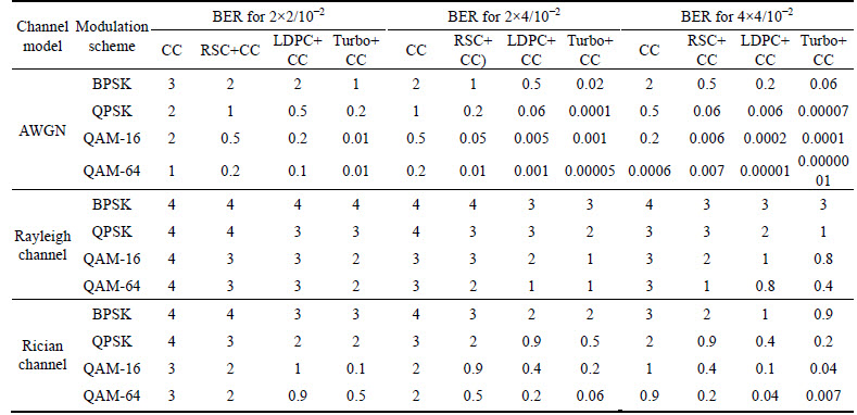
With the similar experimental setup, a color image is transmitted through the MIMO-OFDM system. Since the color image is a three-dimensional matrix, one- dimensional data are constructed from the color image and it is transmitted. The PSNR is determined for the received image and the results are illustrated. Table 1 shows the simulation results for various modulations under various channels with 3 antenna configurations of the error correction codes. The performance of Turbo concatenated with CC is better (shown in bold) in all the channel modulation systems. About 50% reduction of error is seen in Turbo +CC, when compared with the other codes. It is more effective in the QAM-16 and the QAM-64 modulations. In Rayleigh channel, no difference is seen in BPSK modulation for the 2��2 configuration. In Rician channel, LDPC code shows better performance for the 2��2 configuration. On the whole, the 4��4 configuration shows better performance in all the channel modes. Table 2 shows the simulation results for various modulations under various channels with 3 antenna configurations of the error correction codes. The performance of the turbo concatenated with CC is better (shown in bold) in all the channel modulation systems. About 50% reduction of error is seen in Turbo+CC, when compared with the other codes. It is more effective in the QAM-16 and the QAM-64 modulations. In Rayleigh channel, no difference is seen in BPSK modulation for the 2��2 configuration. In Rician channel, the Turbo code and LDPC show better performance. On the whole, the 4��4 configuration shows better performance in all the channel modes.
Table 1 Comparison between concatenated FEC codes under varying channel environments and modulation schemes, while transmitting data
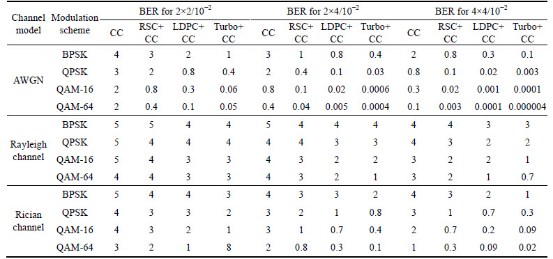
Table 2 Comparison between concatenated FEC codes under varying channel environments and modulation schemes, while transmitting image
6 Conclusion and future work
This work has discussed the performance of MIMO-OFDM system with the concatenated forward error correction codes. The MIMO-OFDM system with the convolutional code has been studied and then, the concatenated error correction codes of the MIMO- OFDM system with different modulations have been analyzed. The graphs have been plotted (BER vs. SNR and PSNR vs. SNR) for all the error correction codes with concatenation (RSC+CC, LDPC+CC, Turbo+CC) and without concatenation (CC). The results of all the error correction codes have been compared, under three different antenna configurations. It has been found that the Turbo code concatenated with convolutional code exhibits the better performance.
References
[1] LIU T H. Analysis of the Alamouti STBC MIMO system with spatial division multiplexing over the Rayleigh fading channel [J]. IEEE Trans on Wirele Commun, 2015, 14: 5156-5170.
[2] LI G, ZHAI H, LI L, LIANG C, YU R, LIU S. AMC-loaded wideband base station antenna for indoor access point in MIMO system [J]. IEEE Transactions on Antennas and Propagation, 2015, 63: 525-533.
[3] SUN S, CHEN C W, CHU S W, CHEN H H, MENG W. Multiuser-interference-free space�Ctime spreading MIMO systems based on three-dimensional complementary codes [J]. IEEE Systems Journal, 2015, 9: 45-57.
[4] RUPP M, MEKLENBRAUKER C F. On extended Alamouti schemes for space-time coding [C]// Proc the 5th Int Symp Wireless Personal Multimedia Commun. IEEE, 2002: 115-119.
[5] SAYED A, YOUNIS W, TARIGHAT A. An invariant matrix structure in multiantenna communications [J]. IEEE Signal Processing Letters, 2005, 12: 749-752.
[6] ZHANG H, WANG Z, YU J, HUANG J. A compact MIMO antenna for wireless communication [J]. IEEE Antennas & Propagation Magazine, 2008�� 50: 104-107.
[7] KIM J, JU J, EOM S, SONG M, KIM N. Four-channel MIMO antenna for WLAN using hybrid structure [J]. Electron Lett, 2013, 49: 857-858.
[8] LI H, XIONG J, HE S. A compact planar MIMO antenna system of four elements with similar radiation characteristics and isolation structure [J]. IEEE Antennas Wireless Propag, 2009, 8: 1107-1110.
[9] LIU L, CHEUNG S W, YUK T I. Compact MIMO antenna for portable devices in UWB applications [J]. IEEE Transactions on Antennas Propag, 2013, 61: 4257-4264.
[10] VUCETIC B, YUAN J. Space�Ctime coding [M]. 1st ed. Hoboken, NJ, USA: Wiley, 2003.
[11] CHEN D, XIA X G, JIANG T, GAO X-q. Properties and power spectral densities of CP based OQAM-OFDM systems [J]. IEEE Transactions on Signal Processing, 2015, 63: 3561-3575.
[12] WANG S H, LI C P, LEE K C, SU H J. A novel low-complexity precoded OFDM system with reduced PAPR [J]. IEEE Transactions on Signal Processing, 2015, 63: 1366-1376.
[13] ALVES T, MORANT M, CARTAXO A, LLORENTE R. Transmission of OFDM wired-wireless quintuple-play services along WDM LR-PONs using centralized broad band impairment compensation [J]. Opt Express, 2012, 20: 13748-13761.
[14] TANG J, LANE P, SHORE K. 30 Gbit/s transmission over 40 km directly modulated DFB laser-based SMF links without optical amplification and dispersion compensation for VSR and metro applications [C]// Optical Fibre Communication Conference. Anaheim, California, 2006.
[15] DJORDJEVIC, VASIC B. Orthogonal frequency division multiplexing for high-speed optical transmission [J]. Opt Express, 2006, 14: 3767-3775.
[16] BINGHAM J A C. Multicarrier modulation for data transmission: An idea whose time has come [J]. IEEE Comm Mag, 1990, 28: 5-14.
[17] CHANG R W. Synthesis of band-limited orthogonal signals for multichannel data transmission [J]. The Bell System Technical Journal, 1966, 45: 1775-1796.
[18] SALTZBERG B R. Performance of an efficient parallel data transmission system [J]. IEEE Transactions on Comm Tech, 1967, 15: 805-811.
[19] HIROSAKI B. An orthogonally multiplexed QAM system using the discrete fourier transform [J]. IEEE Transactions on Comm Tech, 1981, 29: 982-989.
[20] FLOCH B L, ALARD M, BERROU C. Coded orthogonal frequency division multiplex [J]. Proc of the IEEE, 2002, 83: 982-996.
[21] BOLCSKEI H. Orthogonal frequency division multiplexing based on offset QAM [C]// Advances in Gabor Analysis. 2003: 321-352.
[22] BELLANGER M. Physical layer for future broadband radio systems [C]// Radio and Wireless Symposium Conference. New Orleans, LA, USA: IEEE, 2010: 436-439.
[23] ZHANG W, KONG H, XIA X G, LETAIEF K B. Space-time/ frequency coding for MIMO-OFDM in next generation broadband wireless systems [J]. Wireless Communications IEEE, 2007, 14: 32-43.
[24] KASHIMA T, FUKAWA K, SUZUKI H. Adaptive MAP receiver via the EM algorithm and message passings for MIMO-OFDM mobile communications [J]. IEEE J Sel Areas Commun, 2006, 24: 437-447.
[25] PAULRAJ A J, GORE D A, NABAR R U,  H. An overview of MIMO communications��A key to gigabit wireless [J]. Proc IEEE, 2004, 92: 198-218.
[26] SHIN C, HEATH R W, POWERS E J. Blind channel estimation for MIMO-OFDM systems [J]. IEEE Trans on Veh Tech, 2007, 56: 2569-2582.
[27] ROSENHOUSE I, WEISS A J. Combined analog and digital error-correcting codes for analog information source [J]. IEEE Trans on Comm, 2007, 55: 2073-2083.
[28] GALLAGER R G. Low density parity check codes [J]. IRE Trans on Information Theory, 1962, 8: 21-28.
[29] MACKAY D J C, NEAL R M. Near Shannon limit performance of low density parity check codes [J]. Electronic Letters, 1996, 32: 1645-1646.
[30] BOLCSKEI H. MIMO-OFDM wireless systems: Basics, perspectives and challenges [J]. IEEE Wirel Commun, 2006, 13: 31-37.
[31] ALAMOUTI S M. A simple transmit diversity technique for wireless communications [J]. IEEE J Sel Areas Commun, 1998, 16: 1451-1458.
[32] SHAH H, HEDAYAT A, NOSRATINIA A. Performance of concatenated channel codes and orthogonal space-time block codes [J]. IEEE Trans on Wirel Commun, 2006, 5: 1406-1414.
[33] LOSKOT P, BEAULIEU N C. Approximate performance analysis of coded STBC-OFDM systems over arbitrary correlated generalized Ricean fading channels [J]. IEEE Trans on Commun, 2009, 57: 2235-2238.
[34] GUPTA B, SAINI D S. A low complexity decoding scheme of STFBC MIMO-OFDM system [C]// Proc Wireless Advanced (WiAd). London, UK: IEEE, 2012: 176-180.
[35] GUPTA B, SAINI D S. BER analysis of ST-Block coded MIMO-OFDM systems with frequency domain equalization in quasi-static mobile channels [C]// Annual IEEE Proc, India Conf (INDICON). Hyderabad, India, IEEE, 2011: 1-4.
[36] GUPTA, SAINI D S. BER analysis of space-frequency block coded MIMO-OFDM systems using different equalizers in quasi-static mobile radio channel [C]// Proc Communication Systems and Network Technologies (CSNT-11), Conf. Katra, India, 2011: 520-524.
[37] DANIELS R C, CARAMANIS C M, HEATH R W. Adaptation in convolutionally coded MIMO-OFDM wireless systems through supervised learning and SNR ordering [J]. IEEE Trans on Veh Technol, 2010, 59: 114-126.
[38] GUPTA B, SAINI D S. Moment generating function-based pairwise error probability analysis of concatenated low density parity check codes with Alamouti coded multiple input multiple output-orthogonal frequency division multiplexing systems [J]. IET Communications, 2014, 8: 399-412.
[39] BIGDELI M, ABOLHASSANI B. A novel method to derive transfer function and tight ber bound of convolutional codes [J]. Canadian J Electrical and Computer Engineering, 2015, 38: 125-129.
[40] LIU Y, XIA X G, ZHANG H. Distributed linear convolutional space-time coding for two-relay full-duplex asynchronous cooperative networks [J]. IEEE Trans on Wirel Comm, 2013, 12: 6406-6417.
[41] YANG Q, LIEW S C. Asynchronous convolutional-coded physical- layer network coding [J]. IEEE Trans on Wirel Comm, 2015, 14: 1380-1395.
[42] GROSJEAN L, RASMUSSEN L K, THOBABEN R, SKOGLUND M. Systematic LDPC convolutional codes: Asymptotic and finite- length anytime properties [J]. IEEE Trans on Comm, 2014, 62: 4165-4183.
[43] SI Z, THOBABEN R, SKOGLUND M. Bilayer LDPC convolutional codes for decode-and-forward relaying [J]. IEEE Trans on Comm, 2013, 61: 3086-3099.
[44] CHEN L. Iterative soft decoding of reed-solomon convolutional concatenated codes [J]. IEEE Trans on Comm, 2013, 61: 4076-4085.
[45] NGO H A, AHMED S, YANG L L, HANZO L. Non-coherent cooperative communications dispensing with channel estimation relying on erasure insertion aided reed-solomon coded SFH M-ary FSK subjected to partial-band interference and rayleigh fading [J]. IEEE Trans on Comm, 2012, 60: 2177-2186.
[46] KAYA H, OZTURK E. Performance analysis of distributed turbo coded scheme with two ordered best relays [J]. IET Commun, 2015, 9: 638-648.
[47] ZHAN M, WU J. ZHANG Z Z, WEN H, WU J J. Low-complexity error correction for ISO/IEC/IEEE 21451-5 sensor and actuator networks [J]. IEEE Sensors J, 2015, 15: 2622-2630.
(Edited by YANG Hua)
Cite this article as:
Arun Agarwal, Saurabh N. Mehta. Performance analysis and design of MIMO OFDM system using concatenated forward error correction codes [J]. Journal of Central South University, 2017, 24(6): 1322-1343.
DOI:https://dx.doi.org/10.1007/s11771-017-3537-2Received date: 2016-02-26; Accepted date: 2016-09-29
Corresponding author: Arun Agarwal, Assistant Professor, PhD; E-mail: arunagrawal@soauniversity.ac.in
Abstract: This work investigates the performance of various forward error correction codes, by which the MIMO-OFDM system is deployed. To ensure fair investigation, the performance of four modulations, namely, binary phase shift keying (BPSK), quadrature phase shift keying (QPSK), quadrature amplitude modulation (QAM)-16 and QAM-64 with four error correction codes (convolutional code (CC), Reed-Solomon code (RSC)+CC, low density parity check (LDPC)+CC, Turbo+CC) is studied under three channel models (additive white Guassian noise (AWGN), Rayleigh, Rician) and three different antenna configurations(2��2, 2��4, 4��4). The bit error rate (BER) and the peak signal to noise ratio (PSNR) are taken as the measures of performance. The binary data and the color image data are transmitted and the graphs are plotted for various modulations with different channels and error correction codes. Analysis on the performance measures confirm that the Turbo + CC code in 4��4 configurations exhibits better performance.
