
J. Cent. South Univ. Technol. (2011) 18: 755-759
DOI: 10.1007/s11771-011-0759-6![]()
Amplitude phase control for electro-hydraulic servo system based on normalized least-mean-square adaptive filtering algorithm
YAO Jian-jun(Ҧ����)1, FU Wei(����)1, HU Sheng-hai(��ʤ��)1, HAN Jun-wei(����ΰ)2
1. College of Mechanical and Electrical Engineering, Harbin Engineering University, Harbin 150001, China;
2. School of Mechatronics Engineering, Harbin Institute of Technology, Harbin 150001, China
? Central South University Press and Springer-Verlag Berlin Heidelberg 2011
Abstract:
The electro-hydraulic servo system was studied to cancel the amplitude attenuation and phase delay of its sinusoidal response, by developing a network using normalized least-mean-square (LMS) adaptive filtering algorithm. The command input was corrected by weights to generate the desired input for the algorithm, and the feedback was brought into the feedback correction, whose output was the weighted feedback. The weights of the normalized LMS adaptive filtering algorithm were updated on-line according to the estimation error between the desired input and the weighted feedback. Thus, the updated weights were copied to the input correction. The estimation error was forced to zero by the normalized LMS adaptive filtering algorithm such that the weighted feedback was equal to the desired input, making the feedback track the command. The above concept was used as a basis for the development of amplitude phase control. The method has good real-time performance without estimating the system model. The simulation and experiment results show that the proposed amplitude phase control can efficiently cancel the amplitude attenuation and phase delay with high precision.
Key words:
1 Introduction
Hydraulic drives are widely used in industry. Compared with other types of drives, they have many distinct advantages, such as developing a comparatively small device with much larger torque, higher response speed, higher stiffness and higher specific force [1-3]. For an electro-hydraulic servo system, the input to the system is a low-power electrical command, and the output is a variable flow of oil to control a high-power hydraulic actuator. The servo valve consists of a spool with lands machined into it, moving within a cylindrical sleeve. The lands are aligned with apertures cut in the sleeve such that the movement of the spool progressively changes the exposed aperture size and alters the oil flow between two control ports. Compared with the electro- magnetic drives, these systems have much more complicated model. Laminar and turbulent, channel geometry and friction make system equation highly non-linear, and the parameters of hydraulic systems, depending on the relation among flow velocity, pressure and oil viscosity, vary largely [4]. The dynamics performance of a servo valve is influenced by operating conditions, such as pressure, input signal level, fluid and ambient temperature.
As for the control algorithm aspects of hydraulic system, the classical PID controller has been employed in real applications. The PID controller, which uses a combination of proportional, integral and derivative action on the control error, produces the output of the controller. However, because nonlinearities and uncertainty occur in the hydraulic system, the classical PID controller only gives mediocre control performance [5-6]. So, the current research is focused on nonlinear control scheme, which is a control method for adaptively changing the control parameters in real time so as to achieve a desired input-output characteristic even when the dynamic characteristics of the system to be controlled are changed by the operating conditions and environment.
Amplitude attenuation and phase delay occur in the sinusoidal response of the electro-hydraulic servo system. This is very harmful to synchronous control, especially for multi-exciter [7-13]. Though the problem can be solved somewhat by improving the system frequency bandwidth, the system frequency bandwidth is subjected to the hydraulic natural frequency. In Refs.[7-9], controllers for synchronous control were developed based on system dynamic model which is difficult to formulate for the real application. To achieve the precise position synchronous control in Ref.[10], acceleration and speed controllers were designed via the PI control law and the maximum error comparison scheme was developed to reduce the position synchronous errors. This control system was complex and needed system dynamic information. A synchronization strategy based on the Widrow-Hoff learning rule was presented in Ref.[12] for a synchronous hydraulic loading system. A control strategy based on the Widrow-Hoff learning algorithm was proposed in Ref.[13] to accurately track the high frequency harmonic motion for a six-DOF motion simulator. Methods in Refs.[12-13] needed a learning parameter which determined the convergence rate and had a great impact on the system stability. Adaline neural network with the LMS algorithm was applied in Refs.[2, 11] to cancel the phase lag and amplitude attenuation. The step size of the LMS algorithm played an important role. However, the step size should be right selected; otherwise, it would affect its convergence rate, even results in instability.
In this work, a novel amplitude phase control scheme is applied to the electro-hydraulic servo system for compensating the amplitude attenuation and phased delay of its sinusoidal response to achieve high precision tracking performance. Normalized LMS adaptive filtering algorithm is used to on-line update the weights of the proposed scheme in real time.
2 Description of system
The hydraulic system shown in Fig.1 is composed of an asymmetric cylinder, an asymmetric servo valve and a load force. The supply pressure pS is assumed to be constant.
A mathematical model of the plant can be derived from the flow equation of the valve, the continuity equation and the balance of forces at the piston. The valve-flow-rate equation is non-linear and dependent on the valve displacement from neutral [11]. A Taylor series expansion yields
![]() (1)
(1)
where qL is the load flow, Kg is the flow-gain coefficient and Kp is the flow-pressure coefficient.
The load-induced pressure pL is named as
![]() (2)
(2)
where ��=Ao/Ai.
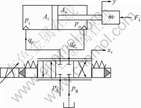
Fig.1 Schematic diagram of hydraulic system: pS��Supply pressure; pR��Return pressure; y��Displacement of piston; m��Total mass of piston and load; FL��Load force; xv��Valve spool position; Ai, Ao��Effective piston areas; ![]() ��Input and output oil flow of cylinder; pi, po��Pressures in two chambers of cylinder
��Input and output oil flow of cylinder; pi, po��Pressures in two chambers of cylinder
The oil flow can also be written as
![]() (3)
(3)
The continuity equations of the cylinder are given:
![]() (4)
(4)
![]() (5)
(5)
where ![]() is the velocity of the piston, and K is the bulk modulus of the hydraulic oil.
is the velocity of the piston, and K is the bulk modulus of the hydraulic oil.
Combining Eqs.(2), (3), (4) and (5) results in the flow continuity equation of the cylinder:
![]() (6)
(6)
where Vt is the total oil volume of the cylinder.
The balance of force at sliding carriage yields
![]() (7)
(7)
where B is the equalized viscous damping coefficient and ![]() is the acceleration of the piston.
is the acceleration of the piston.
Combining Eqs.(1), (6) and (7) and applying the Laplace transformation to the resulting third-order differential equation results in the function [14]:
![]() (8)
(8)
where
![]()
![]()
![]()
In Eq.(8), the load force FL is considered as an external disturbance.
3 Amplitude phase control
When a sinusoidal input is applied to an electro- hydraulic servo system, the system response has seldom the same amplitude and phase as the command. The dynamics of the control system causes the command input to be reduced in amplitude and phase shifted. The unwanted amplitude attenuation and phase delay can be corrected by the network, as shown in Fig.2. The feedback signal is brought into a correction, whose output is compared against the corrected input to develop an estimation error, which is used to update the weight.
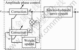
Fig.2 Schematic diagram of amplitude phase control
The normalized LMS adaptive filtering algorithm is used as the adjustment law to update the weight of amplitude phase controller to force the estimation error to be zero. Combined with Fig.2, the normalized LMS adaptive filtering algorithm can be written as [15]
![]() (9)
(9)
where w is the weight vector, x the input vector, d is the desired input and �� is the adaption constant. The LMS is an iterative gradient-descent algorithm that uses an estimate of the gradient on the mean-square error surface to seek the optimum weight vector at the minimum mean-square error point. The term e(k)x(k) represents the estimate of the negative gradient. The true negative gradient is given by the expected value of e(k)x(k). When adapting the LMS on stationary stochastic processes, the expected value of the weight vector converges to a Wiener optimal solution [2,14].
In Eq.(9), the product vector x(k)e(k) is normalized with respect to the squared Euclidean norm of the input vector x. The term ![]() can be viewed as a step size, which is time-varying. The normalized LMS adaptive filtering algorithm can exhibit a rate of convergence that is faster than that of the standard LMS adaptive algorithm [15-18]. �� (��>0) is used to avoid numerical difficulties, because it will be divided by a small value for the squared norm
can be viewed as a step size, which is time-varying. The normalized LMS adaptive filtering algorithm can exhibit a rate of convergence that is faster than that of the standard LMS adaptive algorithm [15-18]. �� (��>0) is used to avoid numerical difficulties, because it will be divided by a small value for the squared norm ![]() when the input vector is small.
when the input vector is small.
For the application of amplitude phase controller, the weight vector is ![]() . The two correction blocks have the same structure. For the input correction, the input vector is comprised of r and rc shifting 90�� phase of r, thus
. The two correction blocks have the same structure. For the input correction, the input vector is comprised of r and rc shifting 90�� phase of r, thus ![]() Using the same process for the feedback correction, its input vector,
Using the same process for the feedback correction, its input vector, ![]() can be obtained, where yc results from shifting 90�� phase of y. The signal d is also used as the desired input for the normalized LMS adaptive filtering algorithm. The weights of the feedback correction are updated according to the estimation error between d and y��. The updated weights are also copied to the input correction. The outputs of the input correction and the feedback correction are
can be obtained, where yc results from shifting 90�� phase of y. The signal d is also used as the desired input for the normalized LMS adaptive filtering algorithm. The weights of the feedback correction are updated according to the estimation error between d and y��. The updated weights are also copied to the input correction. The outputs of the input correction and the feedback correction are ![]() and
and ![]() respectively.
respectively.
When the estimation error is zero, the corrected input, d, as new command input to the system, is equal to the weighted feedback, y��, causing the weight to take on values that compensate the amplitude attenuation and phase delay.
4 Simulation results
In order to illustrate the proposed approach to cancel the amplitude attenuation and phase delay, the signal 0.02sin20��t is used as the command signal during the computer simulation, and FL=0. So, Eq.(8) can be rewritten as
![]() (12)
(12)
To demonstrate the advantages of the proposed control scheme over Refs.[2, 11], the system model in Ref.[11] is applied here for simulation. The model is
![]()
Figure 3(a) shows the system sinusoidal response. It can be seen that there are amplitude attenuation and phase delay. Figure 3(b) shows the system sinusoidal response using the proposed amplitude phase control scheme with ��= 0.03 and ��=10-5. Clearly, the feedback signal has converged to the command signal within 1.5 periods of the fundamental frequency. This shows that the control scheme has good efficiency and accuracy.
Figure 4 shows the plot of estimation error between d and y��, and is used to drive the weights to be updated. From Fig.3(b), there is large tracking error between the command signal and the feedback within 0.1 s, producing large estimation error to generate large force to drive the adjustment of weights. With the effect of weights on the command and the feedback, the feedback asymptotically tracks the command, resulting in a small estimation error. When the feedback entirely tracks the command, the estimation error is zero.
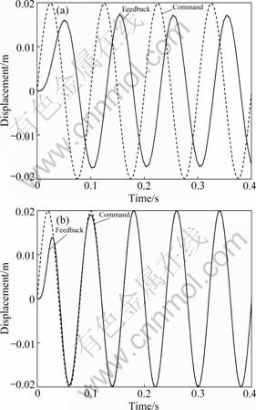
Fig.3 Sinusoidal response: (a) Before amplitude phase control; (b) After amplitude phase control
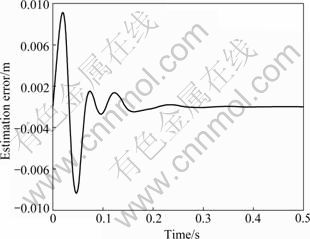
Fig.4 Estimation error
Compared with Refs.[2,11], the proposed control scheme has faster convergence rate, and its operation is simpler, because in Refs.[2, 11], suitable value should be selected for the step size such that it has good convergence rate. At the same time, the system stability should be guaranteed. For this reason, when the command input is changed, the step size will make the corresponding adjustment.
5 Experimental results
The electro-hydraulic servo system used to validate the proposed control scheme is an asymmetric cylinder controlled by a MOOG D792 servo valve, which is a three-stage servo valve. The system parameters are listed in Table 1.
Table 1 System parameters
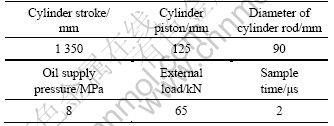
Figures 5 and 6 show the system response when the command inputs are 8sin(2��t) and 5sin(3.4��t), respectively. From Fig.5(a) and Fig.6(a), it can be seen that there are amplitude attenuation and phase delay. What��s more, the problem of amplitude attenuation and phase lag of Fig.6(a) is more serious than that of Fig.5(a). This is dependent on the system frequency characteristics, especially the hydraulic natural frequency.
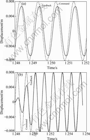
Fig.5 Sinusoidal response with input of 8sin(2��t): (a) Before amplitude phase control; (b) After amplitude phase control
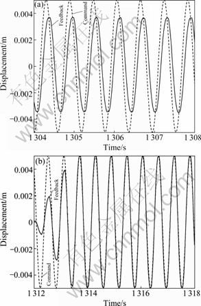
Fig.6 Sinusoidal response with input of 5sin(3.4��t): (a) Before amplitude phase control; (b) After amplitude phase control
The developed amplitude phase control is applied to compensate the system with ��=0.03 and ��=10-5. The results are shown in Fig.5(b) and Fig.6(b). The two figures reveal that the feedback signals have converged to the commands within 2.5 periods of the fundamental frequency. This shows that the control scheme has good tracking performance both in amplitude and in phase.
6 Conclusions
1) Amplitude phase control based on the normalized LMS adaptive filtering algorithm is developed to cancel the amplitude attenuation and phase delay for an electro-hydraulic servo system, and high precision tracking performance is achieved.
2) The proposed control scheme is characterized by its simplicity and applicability for on-line implementation. The non-linear adaptation of the weight vector for the control scheme is performed and an accurate tracking is provided.
3) Compared with related references, the control scheme is simpler to operate and has faster convergence rate, due to its time-varying step size.
4) In the experimentations, though two different commands are applied, the parameters of the LMS adaptive filtering algorithm are unchanged. This shows that the control scheme is easy to operate and has good adaptive ability.
References
[1] MERRIT H E. Hydraulic control system [M]. New York: Wiley, 1976: 1-10.
[2] YAO Jian-jun, WANG Xianc-heng, WU Zhen-shun, HAN Jun-wei. Variable structure control applied in electro-hydraulic servo system with ANN [J]. Chinese Journal of Mechanical Engineering, 2006, 19(1): 32-36.
[3] YAO Jian-jun. Research on acceleration harmonic cancellation of electro-hydraulic servo shaking table [D]. Harbin: Harbin Institute of Technology, 2007. (in Chinese)
[4] YAO Jian-jun, WANG Li-quan, WANG Cai-dong, ZHANG Zhong-lin. ANN-based PID controller for an electro-hydraulic servo system [C]// Proceedings of the IEEE International Conference on Automation and Logistics. Qingdao, 2008: 18-22.
[5] Cervantes I, Jose A R. On the PID tracking control of robot manipulators [J]. System & Control Letters, 2001, 42(3): 37-46.
[6] WU Zhen-shun, YAO Jian-jun, YUE Dong-hai. A self-tuning fuzzy PID controller and its application [J]. Journal of Harbin Institute of Technology, 2004, 36(11): 1578-1580. (in Chinese)
[7] Liu Jiang-hun, Xiong Qing-ping, LI Xian-song. Work on electro-hydraulic synchro-control strategy [J]. Metalforming Machinery, 2000, 35(6): 44-46. (in Chinese)
[8] Jiang Jia-he, Yu Tong-wu, Song Zi-shan. Study of digital control in electrohydraulic servo loading system [J]. Journal of Beijing University of Aeronautics and Astronautics, 2000, 31(3): 318-320. (in Chinese)
[9] Shang Wei-wei, Cong Shuang, ZHANG Yao-xin, LIANG Yan-yang. Active joint synchronization control for a 2-DOF redundantly actuated parallel manipulator [J]. IEEE Transactions on Control Systems Technology, 2009, 17(2): 416-423.
[10] Jeong S K, YON S S. Precise position synchronous control of multi-axis servo system [J]. Mechatronics, 2008, 50(18): 129-140.
[11] YAO Jian-jun, CONG Da-cheng, Jiang Hong-zhou, WU Zhen-shun, HAN Jun-wei. ANN-based adaptive phase corrector applied in electro-hydraulic servo system [J]. Journal of Jilin University: Engineering and Technology Edition, 2007, 37(4): 930-934. (in Chinese)
[12] YAN Hao, YE Zheng-mao, ZHANG Hui, HAN Jun-wei, Zhao Yong, LI Hong-ren. Hydraulic servo systems�� synchronous loading strategy based on Widrow-Hoff learning rules [J]. Earthquake Engineer and Engineering Vibration, 2006, 26(3): 104-107. (in Chinese)
[13] MA Jian-ming, HUANG Qi-tao, CONG Da-cheng, YE Zheng-mao, HAN Jun-wei. Application of the amplitude-phase control strategy in a 6-DOF motion simulator [J]. Journal of Harbin Engineering University, 2008, 29(11): 1216-1221. (in Chinese)
[14] Yao Jian-jun, Wu Zhen-shun, Han Jun-wei, YUE Dong-hai. Adaptive harmonic cancellation applied in electro-hydraulic servo system with ANN [J]. Chinese Journal of Mechanical Engineering. 2004, 17(4): 628-630.
[15] Simon K. Adaptive filter theory [M]. Beijing: Publishing House of Electronics Industry, 2002: 320-352.
[16] Tobias O J, Seara R. On the LMS algorithm with constant and variable leakage factor in a nonlinear environment [J]. IEEE Transactions on Signal Processing, 2006, 54(9): 3448-3458.
[17] Eweda E. A new approach for analyzing the limiting behavior of the normalized LMS algorithm under weak assumptions [J]. Signal Process, 2009, 89(11): 2143-2151.
[18] McLernon D C, LARA M M, Orozco A G. On the convergence of the LMS algorithm with a rank-deficient input autocorrelation matrix [J]. Signal Process, 2009, 89(11): 2244-2250.
(Edited by YANG Bing)
Foundation item: Project(50905037) supported by the National Natural Science Foundation of China; Project(20092304120014) supported by Specialized Research Fund for the Doctoral Program of Higher Education of China; Project(20100471021) supported by the China Postdoctoral Science Foundation; Project(LBH-Q09134) supported by Heilongjiang Postdoctoral Science-Research Foundation, China; Project (HEUFT09013) supported by the Foundation of Harbin Engineering University, China
Received date: 2009-11-19; Accepted date: 2010-02-22
Corresponding author: YAO Jian-jun, Associate Professor, PhD; Tel: +86-451-82519055; E-mail: travisyao@126.com
