
J. Cent. South Univ. (2016) 23: 2705-2719
DOI: 10.1007/s11771-016-3332-5

Behavior of galvanized steel tube subjected to web crippling
HUANG Shu-qiong(������)1, CHEN Yu(����)2, 3, WANG Chao-yang(������)3, DU Guo-feng(�Ź���)2
1. School of Foreign Studies, Yangtze University, Jingzhou 434023, China;
2. School of Urban Construction, Yangtze University, Jingzhou 434023, China;
3. College of Civil Engineering, Huaqiao University, Xiamen 361021, China
 Central South University Press and Springer-Verlag Berlin Heidelberg 2016
Abstract:
The details of a research study of galvanized steel tube under web crippling were presented. A total of 48 galvanized steel square hollow sections with different boundary conditions, loading conditions, bearing lengths and web slenderness were tested. The experimental scheme, failure modes, load-displacement curves and strain intensity distribution curves were also presented. The investigation was focused on the effects of loading condition, bearing length and slenderness on web crippling ultimate capacity, initial compressive stiffness and ductility of galvanized steel tube. The results show that web crippling ultimate capacity increases linearly with the increase of the bearing length under EOF and IOF loading condition. In the end-flange and ITF loading conditions, strain intensity of the centerline of web reaches the peak and decreases progressively from central web to flanges. Finite element models were developed to numerically simulate the tests in terms of failure modes and ultimate capacity. Web crippling strength of galvanized steel tube increases linearly with the increase of the ratio of the bearing length to web thickness and decrease of web slenderness. The effect of ratio of galvanized layer thickness to web thickness on web crippling strength is small. Based on the results of the parametric study, a number of calculation formulas proposed in this work can be successfully employed as a design rule for predicting web crippling ultimate capacity of galvanized steel tube under four loading and boundary conditions.
Key words:
1 Introduction
Steel tubular trusses are increasingly used because of their capacity for large spans and attractive esthetic appearance. Many research studies have been carried out to investigate the behavior and resistance of the tubular steel and concrete filled tube structures. These steel structures must also be protected from the environment to guarantee their service life and galvanizing is the most common way of protection [1]. Because of the high cost of stainless steel truss and beam, the galvanized truss and beam has been widely applied in domestic and foreign buildings. However, in the absence of the stiffeners, the webs of galvanized steel tube are easy to buckle outward due to concentrated transverse forces from purlins. Therefore, web crippling must be considered in designing galvanized steel tube.
Previous research on web crippling property of steel structures is mainly focused on carbon steel and aluminum members. Cold-formed steel members subjected to web crippling have been tested [2-4]. Web crippling of stainless steel tubular members have been investigated experimentally [5-8]. Investigation of aluminum tubular sections subjected to end bearing force and web crippling have been reported [9-11]. Strengthening of rectangular carbon steel tubes and light steel beams using CFRP subjected to end bearing loads have been reported [12-16].
LANDA and LGLESIAS [17] focused on the size, position and shape of the vent holes for galvanization purposes.  et al [18] evaluated the influence of different vent hole geometries and welding on the strength of galvanized rectangular hollow sections K-joints typically used in tubular warren lattice girders. SERRANO et al [19] evaluated the influence of holes on the mechanical resistance of K-joints in hot-dip galvanized tubular structures. The test program examined the effects of a number of variables, including the presence or absence of the vent hole, the dimensions of the RHS, the ratio of the brace/chord wall thicknesses and the angle between the brace and the chord members. However, these investigations focusing on the mechanical property of galvanized truss did not consider strength in the web of the sections. Little research has reported on web crippling strengthening of galvanized steel tube.
Currently, there is little research on galvanized steel tubular sections under four loading conditions for web crippling, and the four loading conditions are end-two- flange (ETF), interior-two-flange (ITF), end-one-flange (EOF) and interior-one-flange (IOF) loadings. In this work, a series of web crippling tests of galvanized steel tubular structural members was conducted. The test specimens were subjected to ETF, ITF, EOF and IOF loading conditions. The tests were performed on four different hollow section sizes which covered a range of web slenderness ratio from 18 to 43. The load-web deformation behavior, failure loads and failure modes of galvanized steel tubular sections under web crippling were presented.
2 Experimental investigation
2.1 Test specimens
Experimental investigations were designed to examine the influence of various boundary and loading parameters on web crippling ultimate capacity. A total of 48 galvanized steel square hollow sections with different boundary condition, loading condition, section height, and bearing length were tested in Table 1. The specimen had the nominal webs thickness (t) ranging from 1.5 to 2.1 mm, the nominal webs heights (h) ranging from 37 to 101 mm, and the flange widths (b) ranging from 37 to 100 mm. The measured ratio of the height to the thickness (web slenderness) of the webs ranged from 18 to 43. Galvanized layer thickness (tg) is measured about 0.15 mm. The symbols of galvanized steel tube sections are defied in Fig. 1.
The rigid bearing plates were fabricated with chinese standard Q345 steel having the nominal thickness of 30 mm. All the bearing plates were machined to specified dimensions, and the length was 300 mm. The bearing plates were designed to act across the full flange widths of the specimen sections, so as to ensure the overall displacement loading.
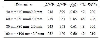
In this work, the specimens were tested in four loading conditions, namely, end-one-flange (EOF), interior-one-flange (IOF), end-two-flange (ETF) and interior-two-flange (ITF). In order to eliminate the boundary effect, the distance from the edge of the bearing plate to the end of the member was set to be at least 1.5 times the overall depth of the web. Figure 2 shows photographs of web crippling tests in four boundary and loading conditions.
2.2 Specimen labeling
In Table 1, all specimens were labeled to easily identify material type of the specimens, section geometry, and the loading condition, as the well as length of the bearing could be identified from the label. For example, the label ��SHSGST60-EOF-N100�� is defined as the following specimens:
1) The first three letters ��SHS�� indicate square hollow section;
2) The following three letters indicate the material type of the specimens, where ��GST�� refers to galvanized steel tube;
3) The notation ��60�� indicates the section overall height in mm (60 mm). The other ��40��, ��80�� and ��100�� mean the nominal overall height (h) of 40, 80 and 100 mm in the test, respectively;
4) The following three letters indicate the loading and boundary condition, where EOF refers to end-one- flange test. IOF refers to interior-one-flange test. ETF refers to end-two-flange test. ITF refers to interior-two- flange test;
5) The notation ��N100�� indicates the bearing plate width in mm, where ��100�� means the nominal bearing length (a) of 100 mm. The other ��50�� and ��150�� mean the nominal bearing length (a) of 50 and 100 mm, respectively.
2.3 Material properties
The material properties of the galvanized steel tube specimens were determined from a series of tensile tests. The tensile coupons were taken from the centre of the web plate in the longitudinal direction of the untested specimens. The nominal coupons were prepared and tested according to Chinese Metallic Materials-Tensile testing at ambient temperature (GB/T228-2002) [20], The coupons were tested in an MTS displacement controlled the testing machine using friction grips. The strain gauges and a calibrated extensometer were used to measure the longitudinal strain. A data acquisition system was used to record the load and strain at regular intervals during the tests. The material properties obtained from the tensile coupon tests are summarized in Table 2, including the tensile yield stress (fy), the ultimate tensile stress (fu), ratio of the tensile yield stress to the ultimate tensile stress (fy/fu), the elongation after fracture (��) and the elastic modulus (E). The galvanized steel tube has lower yield strength and better ductility than low carbon steel, as shown in Table 2.
2.4 Test program
In all structural design, an accurate prediction of the ultimate capacity of galvanized steel tube under web crippling is required for an efficient and safe use. The local transverse resistance of the web crippling specimens was obtained according to European steel structures design code [21], which can be used as the estimated load. In the actual control, the upper limit of graded load is continuously adjusted according to the displacement gauges feedback. At the appearance of obviously large displacement or drop load, the tests were stopped.
Table 1 Parameters and ultimate capacity of galvanized steel tubular sections subjected to web crippling

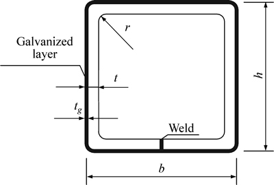
Fig. 1 Definition of symbols of galvanized steel tubular sections
Table 2 Result of galvanized steel tube material characteristic coupe test
Two displacement gauges D1 and D2 were located at the surface of the bearing plates on the top flange of galvanized steel tube sections in order to record the vertical displacement during the test, as shown in Fig. 3(a). Five strain gauge rosettes (T1-T5), which enabled strain values to be measured simultaneously, were distributed at the same interval on the web of aluminum square hollow sections, as shown in Fig. 3(b).
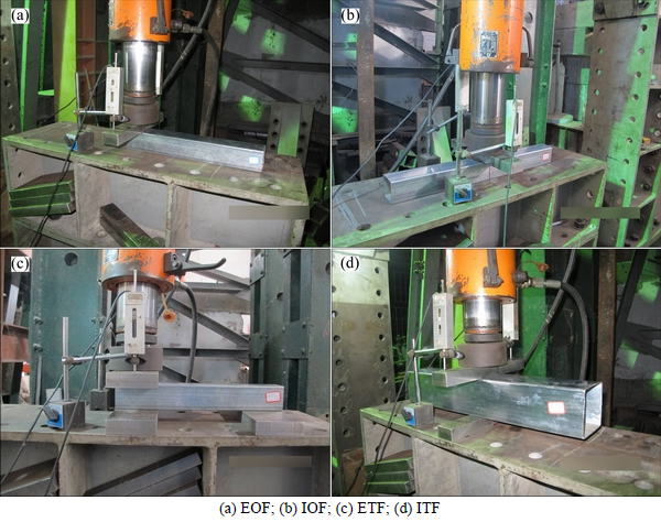
Fig. 2 Photos of web crippling tests under four boundary and loading conditions:
Fig. 3 Arrangement of displacement and strain gauges:
3 Test results
3.1 Failure modes
All types of failure modes in four loading conditions were observed from the web crippling tests, as shown in Figs. 4(a)-(b), respectively. The webs of the specimens were buckled outward; it is obvious plastic hinge zone formed in the middle parts of the webs in the ultimate limit state. The loading flange was involved in concave deformation under IOF loading condition; two flanges are also involved in concave deformation under ITF, EOF and ETF loading condition. Obvious cracks in galvanized layer are observed in the serious web buckling location when web slenderness of the specimens is relatively small (S=(h-2t)/t=18).
3.2 Effect of bearing lengths
Table 3 shows the ultimate capacity of galvanized steel tube subjected to web crippling with different bearing lengths. It is shown that as the bearing length increases, the web crippling ultimate capacity enhancement also increases obviously under the four loading conditions. For example, increasing the bearing length from 50 to 100 and 150 mm, the minimum enhancement of web crippling ultimate capacity is found to be 12% and 28% for ITF loading condition, the maximum enhancement of web crippling ultimate capacity is found to be 72% and 121% for ETF loading condition. For example, increasing the bearing length from 50 to 100 and 150 mm, it is found that the mean values of web crippling ultimate capacity enhancement increase by 51% and 100% under EOF loading condition compared with 63% and 112% under ETF loading condition. Meanwhile, increasing bearing length ranges from 50 to 100 and 150 mm, it is found that the mean values of web crippling ultimate capacity enhancement increase by 40% and 80% under IOF loading condition compared with 31% and 71% under ITF loading condition. It is shown that the effect of the bearing length on the web crippling ultimate capacity of galvanized steel tube in end-flange loading condition is more obvious than those of galvanized steel tube in interior-flange loading condition. The web crippling ultimate capacity of galvanized steel tube increases linearly with the increase of the bearing length under EOF and IOF loading condition. The effect of the bearing length on the web crippling ultimate capacity of galvanized steel tube under ETF loading condition is more obvious than those of tube under EOF loading condition. The effect of the bearing length on the web crippling ultimate capacity of galvanized steel tube under IOF loading condition is more obvious than those of tube under ITF loading condition.
3.3 Effect of web slenderness
Figure 5 plots the web crippling ultimate capacity versus the web slenderness curves under four boundary and loading conditions. The measured web slenderness values of the tubular sections range from 18 to 43. Under end-flange loading condition, the values of web crippling ultimate capacity of the specimens are minimum and almost the same when the web slenderness ratio ranges from 28 to 43, and the values of web crippling ultimate capacity of the specimens with the web slenderness ratio of 18 reach its peak. Under interior-flange loading condition, the values of web crippling ultimate capacity of the specimens are minimum when the web slenderness ratio is 28. However, when the bearing length is 50 mm, the values of web crippling ultimate capacity of the specimens with the web slenderness ratio=43 reach its peak; when the bearing length is 100 and 150 mm, the values of web crippling ultimate capacity of the specimens with the web slenderness ratio of 18 reach its peak.

Fig. 4 Photos of failure modes under four boundary and loading condition:
Table 3 Comparison of ultimate capacity of galvanized steel tubular sections subjected to web crippling with different bearing lengths
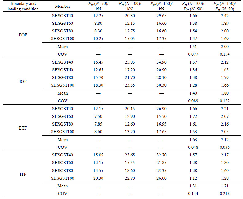
Figure 6 shows that the typical load-displacement curves of galvanized steel tubular sections subjected to web crippling with different web slenderness under four boundary and loading conditions. Ductility ratio is defined as ratio of displacement at ultimate load to displacement at yield load of all specimens based on the design criteria recommended by KUROBANE et al [22]. It can be observed from Fig. 7 that as the web slenderness ratio is 18, the values of the web crippling ultimate capacity are almost maximum, but after reaching peak, the load-displacement curves fall fast and the ductilities of specimens are poor. Similarly, it can be observed from Fig. 6 that as the web slenderness ratio is 28, the specimens have lowest ultimate capacity and poor ductility. It is shown that as the web slenderness ratio is 43, the specimens have second largest ultimate capacity, and after reaching peak, the load-displacement curve falls slowly and the ductility is good.
3.4 Effect of boundary and loading conditions
The comparison of the ultimate capacity of galvanized steel tubular sections subjected to web crippling under different boundary and loading conditions is shown in Fig. 7. It is shown that the values of the web crippling ultimate capacity under IOF loading condition are larger than those in ITF loading condition. The values of the ultimate capacity under EOF and ETF boundary and loading conditions are the minimum.

Fig. 5 Comparison of capacity of galvanized steel tubular sections subjected to web crippling with different web slenderness:
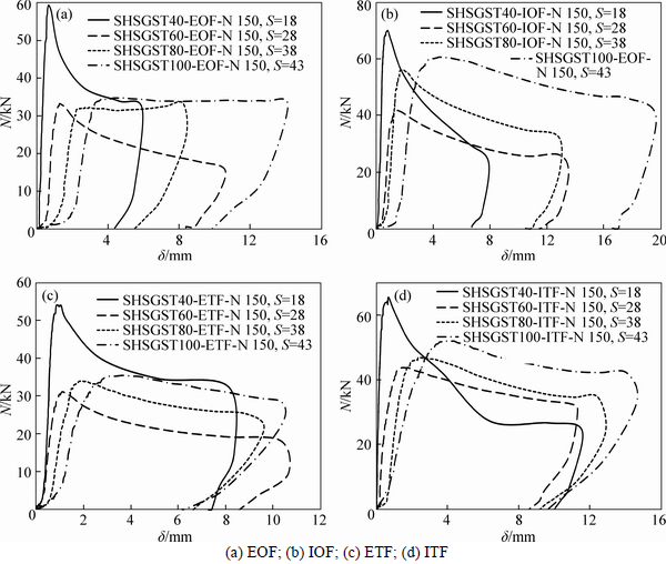
Fig. 6 Load-displacement curves of galvanized steel tubular sections subjected to web crippling with different web slenderness:
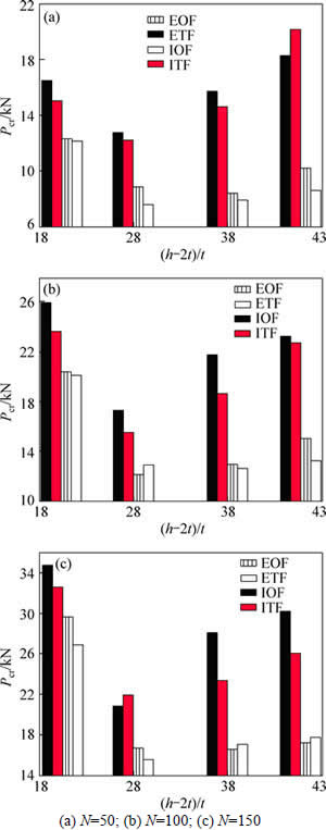
Fig. 7 Comparison of capacity of galvanized steel tubular sections subjected to web crippling under different boundary and loading conditions:
The load-displacement curves of galvanized steel tubular sections subjected to web crippling under different loading conditions are plotted in Fig. 8. It is observed that the initial axial compressive stiffnesses of the specimens under four different boundary and loading conditions are relatively the same, and the specimens under IOF and ITF boundary and loading conditions have high ultimate capacity and good ductility. For galvanized steel tubular sections SHSGST80-EOF-N150 and SHSGST100-EOF-N150 having obvious plastic deformation, the ultimate capacity remains constant or even larger than those values in elastic phase.
3.5 Load-strain intensity on web face curves
Strain distributions at the face of web region are derived from the readings of three-element rosettes strain gauges and the failure mechanism of galvanized steel tubular sections subjected to web crippling is studied. The strains at the measuring points of strain gauges under different load levels of typical specimens are plotted in Fig. 9, in which the horizontal axis represents the measuring point of strain gauges (as shown in Fig. 3(b)), the vertical axis represents the strain (��i), and the dash line represents the strain corresponding to the yield load. The strain (��i) could be calculated as follows [23-24]:
 (1)
(1)
where ��1, ��2 and ��3 are the first, second and third principal strains, respectively, which are obtained from three- element rosettes strain gauges along the web region.
The strain intensity distribution curves of galvanized steel tubular sections are shown in Fig. 9. In the end-flange and ITF loading conditions, strain intensity of T3 located at the centerline of web reaches the peak and decreases progressively from central web to flanges. Under the IOF loading condition, the center and upper parts of web are buckled outward and strain intensity of T1 and T2 keep the maximum values.
4 Comparison of web crippling ultimate capacity
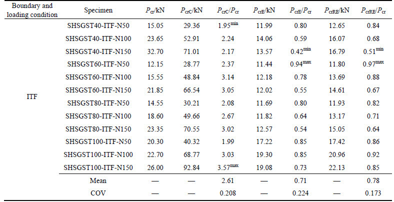
The experimental web crippling ultimate capacity (Pcr) and the calculated value using specification under EOF, IOF, ETF and ITF boundary and loading condition are given in Table 4, respectively. The specification values are calculated using geometry size of galvanized steel tubular sections and the measured yield strength. PcrC and PcrE are the web crippling ultimate capacity of galvanized steel tubular sections obtained by using Chinese steel structures design code (GB50017-2003) [25] and European design of steel structures (Eurocode 3) [21], respectively.
The mean values of PcrC/Pcr (where PcrC capacity obtained by using Chinese steel structures design code) ratio are 3.68, 2.40, 3.95 and 2.61 with the corresponding COV of 0.241, 0.169, 0.237 and 0.208 under EOF, IOF, ETF and ITF boundary and loading conditions, respectively. The calculated result obtained by using Chinese steel structures design code PcrC is far larger than Pcr, because that the ultimate capacity reduction caused by out-of- plane buckling of the thin web and effects of loading and boundary conditions on web crippling ultimate capacity are not considered in Chinese steel structures design code. The mean values of PcrE/Pcr ratio are 0.39, 0.63, 0.46 and 0.71 with the corresponding COV of 0.283, 0.192, 0.315 and 0.224 under EOF, IOF, ETF and ITF boundary and loading conditions, respectively. It is shown that the calculated result obtained by using European steel structures design code is very conservative.

Fig. 8 Load-displacement curves of galvanized steel tubular sections subjected to web crippling under different boundary and loading conditions:
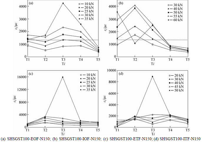
Fig. 9 Strain intensity distribution curves:
Table 4 Comparison of capacity of galvanized steel tubular sections subjected to web crippling between test and code

Continued
5 Finite element analysis
5.1 Verification of FEM
The finite element software ABAQUS version 6.11 [26] is used to develop finite element models for galvanized steel tubular sections subjected to web crippling loading. The model is based on centerline dimensions determined from measured geometry reported in Table 1. The bearing plates are modeled using analytical rigid plates, the I-beams and galvanized layers are modeled using the C3D8I solid elements. The convergence studies are carried out to obtain the optimum finite element mesh density. Both material and geometric nonlinearities have been taken into account in the finite element model. The bilinear material model based on the elastic modulus and post-yield tangential modulus of steel obtained from the tensile coupon tests is developed for the material modeling, while the Von-Mises yield criterion is applied which is normally used to estimate the yielding of the ductile materials. The typical finite element mesh of galvanized steel sections is shown in Fig. 10.
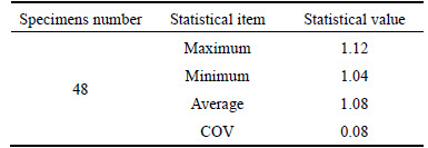
Finite element models are developed under EOF, IOF, ETF and ITF boundary and loading conditions. It is necessary to verify the FEM. In the verification of the FEM, a total of 48 galvanized steel square hollow sections subjected to web crippling are analyzed. A comparison between the experimental results and the finite element results is carried out. The main objective of this comparison is to verify and check the accuracy of the FEM. The finite element models are verified against the experimental results in terms of failure modes and ultimate capacity. The failure modes obtained from the tests of galvanized steel square hollow sections in Fig. 4 are compared with the FE predictions in Fig. 11. It can be seen that the failure mode predicted by the FEA is in good agreement with the laboratory test results. A comparison of the test results (PTest) with finite element analysis results (PFEA) of the web crippling ultimate capacities is shown in Table 5. It can be seen that good agreement has been achieved between both results for all specimens. The mean value of the PFEA/PTest ratio is 1.08 with the corresponding COV of 0.080. The minimum error is 4% and the maximum error is 12%. It is shown that good agreement is achieved between the experimental and finite element results for both the web crippling strength and failure mode.
5.2 Parametric study
The finite element model developed closely predicts the experimental ultimate capacity and failure modes of the galvanized steel tube sections subjected to web crippling. Using this calibrated model, parametric studies are carried out to study the effects of bearing length, web slenderness and galvanized layer thickness on the web crippling ultimate capacity of galvanized steel tube sections subjected to web crippling under EOF, IOF, ETF and ITF loading conditions. The web crippling ultimate capacity predicted is influenced primarily by the ratio of the bearing length to web thickness a/t, the ratio of section effective height to web thickness (h-2t)/t and the ratio of galvanized layer thickness to web thickness (tg/t). In order to find the effect of a/t, (h-2t)/t and tg/t on web crippling ultimate capacity, parametric studies are carried out. The specimens having 200 mm height sections consist of the ratio of the bearing length to web thickness a/t ranging from 10 to 160 and web slenderness ((h-2t)/t) value ranging from 10 to 110. The ratios of galvanized layer thickness to web thickness (tg/t) are 0.1, 0.2, 0.3 and 0.4, as shown in Table 6.

Fig. 10 Typical finite element mesh of galvanized steel tubular sections

Fig. 11 Failure mode attained from finite element analysis:
Table 5 Statistical result of PFEA/PTest
Under the EOF, IOF, ETF and ITF loading conditions, a total of 576 numerical specimens is analyzed in the parametric study investigating the effect of the ratio a/t, (h-2t)/t and tg/t. The effects of a/t, (h-2t)/t and tg/t ratios on the web crippling ultimate capacity of galvanized steel tube under four loading conditions are shown in Figs. 12(a)-(c), respectively. It is seen from these graphs that the parameters a/t and (h-2t)/t noticeably affect the web crippling ultimate capacity. It is demonstrated from Fig. 12(a) that the web crippling ultimate capacity of galvanized steel tube increases linearly with the increase of the a/t value. It is shown from Fig. 12(b) that the web crippling ultimate capacity of galvanized steel tube decreases linearly with the increase of the (h-2t)/t value. The effect of parameter tg/t ratio on web crippling ultimate capacity is small, as shown in Fig.12(c).
Table 6 Values of parameters in parametric study
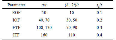

Fig. 12 Ultimate capacity-geometrical parameter curves of galvanized steel tubular sections subjected to web crippling in parametric study:
6 Design formulas
Based on material strength failure of local compressive web, the calculated results obtained by using Chinese steel structures design code are far larger than the experimental value. Because the small effect of bearing length on the web crippling strength in European steel structures design code, the calculation obtained by using European steel structures design code is generally quite conservative.
The calculation equations of web crippling ultimate capacity under four boundary and loading conditions according to European steel structures design code are very complicated and more conservative, so the effect of the bearing length is considered to be improved. Based on the results of the parametric study, this work puts forward more accurate calculation formulas (2)-(5) of galvanized steel beam web crippling ultimate capacity. The design values can be reduced appropriately according to the importance of structure. The calculation formulas can accurately predict experimental value, the mean values of ratio of the calculation values obtained by using calculation formulas (2)-(5) to experimental values are 0.79, 0.84, 0.80 and 0.78 with the corresponding COV of 0.225, 0.142, 0.213 and 0.173 under EOF, IOF, ETF and ITF boundary and loading condition in Table 4, respectively.
The web crippling ultimate capacity of galvanized steel square hollow sections under four boundary and loading condition are calculated using calculation formulas (2)-(5) as follows:
 (2)
(2)
 (3)
(3)
 (4)
(4)
 (5)
(5)
where PEOF is web crippling ultimate capacity under EOF condition; PIOF is web crippling ultimate capacity under IOF condition; PETF is web crippling ultimate capacity under ETF condition; PITF is web crippling ultimate capacity under ITF condition; fy is yield stress of aluminum alloy tube; h is web height of aluminum alloy tube; t is web thickness of aluminum alloy tube; a is bearing lengthl.
7 Conclusions
An experimental investigation of galvanized steel square hollow sections under four loading and boundary conditions subjected to web crippling is presented. The ultimate capacity, failure modes, local deformations and strain intensity distributions of typical specimens are reported. In addition, the corresponding finite element analysis is also performed and the validated FE model is used for the parametric study to evaluate the effects of main geometric parameters on the mechanical behavior of galvanized steel square hollow sections subjected to web crippling. Based on the experimental and numerical investigations, the following conclusions can be drawn.
1) Cracks appear on the corner of galvanized steel tube in the ultimate limit state.
2) The effect of the bearing length on the web crippling ultimate capacity of galvanized steel tube under ETF loading condition is more obvious than those of tube under EOF loading condition. The effect of the bearing length on the web crippling ultimate capacity of galvanized steel tube under IOF loading condition is more obvious than those of tube under ITF loading condition.
3) The initial axial compressive stiffnesses of the specimens under four different boundary and loading conditions are relatively the same.
4) Ratio of the bearing length to web thickness and web slenderness noticeably affects the web crippling strength in parametric study calibrated with test result.
5) The proposed design formulas put forward can predict ultimate capacity of galvanized steel tube subjected to web crippling.
Nomenclature
EOF
End-one-flange boundary and loading condition
IOF
Interior-one-flange boundary and loading condition
ETF
End-two-flange boundary and loading condition
ITF
Interior-two-flange boundary and loading condition
Pcr
Experimental web crippling ultimate capacity
PcrC
Web crippling ultimate capacity obtained by using Chinese steel structures design code (GB50017-2003)
PcrE
Web crippling ultimate capacity obtained by using European design of steel structures (Eurocode 3)
PFEA
Web crippling ultimate capacity obtained by using finite element analysis
PcrRE
Web crippling ultimate capacity obtained by using formulas this work put forward
PEOF
Web crippling ultimate capacity under EOF condition
PIOF
Web crippling ultimate capacity under IOF condition
PETF
Web crippling ultimate capacity under ETF condition
PITF
Web crippling ultimate capacity under ITF condition
fy
Tensile yield stress
fu
Ultimate tensile stress
��
Elongation after fracture
E
Elastic modulus
h
Overall height of galvanized steel tubular section
b
Overall width of galvanized steel tubular section
r
Internal arc radius
t
Wall thickness of galvanized steel tubular section
tg
Wall thickness of galvanized layer
L
Overall length of galvanized steel tubular section
a
Bearing length
a/t
Ratio of bearing length to web thickness
(h-2t)/t
Web slenderness
tg/t
Ratio of galvanized layer thickness to web thickness
��i
Strain intensity
��1
First principal strain
��2
Second principal strain
��3
Third principal strain
References
[1] GLINDE H, JOHAL I. Zinc and its uses. Protective for humans and steel hot dip galvanizing magazine [M]. Galvanizers Association, 2011: 23-26.
[2] YOUNG B, HANCOCK G J. Web crippling of cold-formed unlipped channels with flanges restrained [J]. Thin-Walled Structures, 2004, 42: 911-930.
[3] MACDONALD M, HEIYANTUDUWA M A, KOTELKO M, RHODES J. Web crippling behaviour of thin-walled lipped channel beams [J]. Thin-Walled Structures, 2011, 49(5): 682-690.
[4] CHEN Y, CHEN X X, WANG C Y. Experimental and finite element analysis research on cold-formed steel lipped channel beams under web crippling [J]. Thin-Walled Structures, 2015, 87(2): 41-52.
[5] ZHOU F, YOUNG B. Cold-formed stainless steel sections subjected to web crippling [J]. Journal of Structural Engineering. ASCE, 2006, 132(1): 134-144.
[6] ZHOU F, YOUNG B. Experimental and numerical investigations of cold-formed stainless steel tubular sections subjected to concentrated bearing load [J]. Journal of Constructional Steel Research, 2007, 63(11): 1452-1466.
[7] ZHOU F, YOUNG B. Cold-formed high-strength stainless steel tubular sections subjected to web crippling [J]. Journal of Structural Engineering ASCE, 2007, 133(3): 368-377.
[8] ZHOU F, YOUNG B. Web crippling behaviour of cold-formed duplex stainless steel tubular sections at elevated temperatures [J]. Engineering Structures, 2013, 57: 51-62.
[9] ZHOU F, YOUNG B. Aluminum tubular sections subjected to web crippling��Part I: Tests and finite element analysis [J]. Thin-Walled Structures, 2008, 46: 339-351.
[10] ZHOU F, YOUNG B. Aluminum tubular sections subjected to web crippling��Part II: Proposed design equations [J]. Thin-Walled Structures, 2008, 46: 352-361.
[11] ZHOU F, YOUNG B. Web crippling of aluminium tubes with perforated webs [J]. Engineering Structures, 2010, 32: 1397-1410.
[12] ZHAO X L, FERNANDO D, AL-MAHAIDI R. CFRP strengthened RHS subjected to transverse end bearing force [J]. Engineering Structures, 2006, 28(11): 1555-1565.
[13] ZHAO X L, AL-MAHAIDI R. Web buckling of light steel beams strengthened with CFRP subjected to end bearing forces [J]. Thin-Walled Structures, 2009, 47: 1029-1036.
[14] FERNANDO D, YU T, TENG J G, ZHAO X L. CFRP strengthening of rectangular steel tubes subjected to end bearing loads: effect of adhesive properties and finite element modeling [J]. Thin-Walled Structures, 2009, 47: 1020-1028.
[15] ISLAM S M Z, YOUNG B. Web crippling of aluminium tubular structural members strengthened by CFRP [J]. Thin-Walled Structures, 2012, 59(4): 58-69.
[16] ZAHURUL I S M, YOUNG B. Ferritic stainless steel tubular members strengthened with high modulus CFRP plate subjected to web crippling [J]. Journal of Constructional Steel Research, 2012, 77: 107-118.
[17] LANDA P, IGLESIAS G. Cidect project 14B. Monograph on hot-dip galvanized tubular structures: Design recommendations for holes due to galvanizing process [R]. Netherland: CIDECT, 2007.
[18] J J, SERRANO M A, COLINA C,  M A S, RABANAL F P
  . Effect of the vent hole geometry and welding on the static strength of galvanized RHS K-joints by FEM and DOE [J]. Engineering Structures, 2012, 41(3): 218-233.
[19] SERRANO M A, COLINA C, J J. Static behavior of compressed braces in RHS K-joints of hot-dip galvanized trusses [J]. Journal of Constructional Steel Research, 2013, 89: 307-316.
[20] GB/T 228-2002. Metallic materials-tensile testing at ambient temperature [S]. (in Chinese)
[21] EN 1993-1-8, CEN. Design of steel structures��Part 1-3: General rules-Supplementary rules for cold-formed members and sheeting [S].
[22] KUROBANE Y, MAKINO Y, OCHI K. Ultimate resistance of unstiffened tubular joints [J]. Journal of Structural Engineering, ASCE, 1984, 110(2): 385-400.
[23] WANG W, CHEN Y Y, MENG X D, LEON R T. Behavior of thick-walled CHS X-joints under cyclic out-of-plane bending [J]. Journal of Constructional Steel Research, 2010, 66(6): 826-834.
[24] CHEN Y, FENG R, WANG J. Behaviour of bird-beak square hollow section X-joints under in-plane bending [J]. Thin-Walled Structures, 2015, 86(3): 94-107.
[25] GB50017-2003. Code for design of steel structure [S]. (in Chinese)
[26] ABAQUS. Standard user's manual. Version 6.11. Hibbitt, Karlsson and Sorensen, Inc. Vols. 1-3, Version 6.11. USA. 2006.
(Edited by FANG Jing-hua)
Foundation item: Projects(51278209, 51378077, 51478047) supported by the National Natural Science Foundation of China; Project(ZQN-PY110) supported by Promotion Program for Young and Middle-aged Teacher in Science and Technology Research of Huaqiao University, China; Project(2014FJ-NCET-ZR03) supported by Program for New Century Excellent Talents in Fujian Province University, China; Project(JA13005) supported by Incubation Program for Excellent Young Science and Technology Talents in Fujian Province Universities, China
Received date: 2015-06-17; Accepted date: 2015-12-10
Corresponding author: CHEN Yu, PhD, Professor; Tel: +86-716-8061538; E-mail: kinkingingin@163.com
Abstract: The details of a research study of galvanized steel tube under web crippling were presented. A total of 48 galvanized steel square hollow sections with different boundary conditions, loading conditions, bearing lengths and web slenderness were tested. The experimental scheme, failure modes, load-displacement curves and strain intensity distribution curves were also presented. The investigation was focused on the effects of loading condition, bearing length and slenderness on web crippling ultimate capacity, initial compressive stiffness and ductility of galvanized steel tube. The results show that web crippling ultimate capacity increases linearly with the increase of the bearing length under EOF and IOF loading condition. In the end-flange and ITF loading conditions, strain intensity of the centerline of web reaches the peak and decreases progressively from central web to flanges. Finite element models were developed to numerically simulate the tests in terms of failure modes and ultimate capacity. Web crippling strength of galvanized steel tube increases linearly with the increase of the ratio of the bearing length to web thickness and decrease of web slenderness. The effect of ratio of galvanized layer thickness to web thickness on web crippling strength is small. Based on the results of the parametric study, a number of calculation formulas proposed in this work can be successfully employed as a design rule for predicting web crippling ultimate capacity of galvanized steel tube under four loading and boundary conditions.
