

J. Cent. South Univ. (2018) 25: 1948-1957
DOI: https://doi.org/10.1007/s11771-018-3885-6

Effects of different poses and wind speeds on flow field of dish solar concentrator based on virtual wind tunnel experiment with constant wind
LIU Guan-lin(������)1, 2, E Jia-qiang(����ǿ)1, 3, LIU Teng(����)1, 3,ZUO Wei(����)1, 3, ZHANG Qing-ling(������)1, 3
1. College of Mechanical and Vehicle Engineering, Hunan University, Changsha 410082, China;
2. School of Mechanical Engineering, Hunan International Economics University, Changsha 410205, China;
3. Institute of New Energy and Energy-Saving & Emission-Reduction Technology, Changsha 410082, China
 Central South University Press and Springer-Verlag GmbH Germany, part of Springer Nature 2018
Abstract:
In order to improve structure performance of the dish solar concentrator, a three-dimensional model of dish solar concentrator was established based on the high-precision numerical algorithms. And a virtual wind tunnel experiment with constant wind is adopted to investigate the pressure distribution of the reflective surface, velocity distribution of the fluid domain for the dish solar concentrator in different poses and wind speeds distribution. Some results about wind pressure distribution before and after dish solar concentrator surface and wind load velocity distribution in the entire fluid domain had been obtained. In particular, it is necessary to point out that the stiffness at the center of the dish solar concentrator should be relatively raised. The results can provide a theoretical basis for the improvement of solar concentrator dish structure as well as the failure analysis of dish solar concentrator in engineering practice.
Key words:
Cite this article as:
LIU Guan-lin, E Jia-qiang, LIU Teng, ZUO Wei, ZHANG Qing-ling. Effects of different poses and wind speeds on flow field of dish solar concentrator based on virtual wind tunnel experiment with constant wind [J]. Journal of Central South University, 2018, 25(8): 1948�C1957.
DOI:https://dx.doi.org/https://doi.org/10.1007/s11771-018-3885-61 Introduction
Compared with power generation from fossil fuels [1�C3] and biomass [4�C7], solar thermal power generation is useful for reducing carbon dioxide emissions and delaying the consumption of fossil fuels [8�C10]. In the field of the solar thermal power technologies [11�C13] including dish solar thermal power generation system, tower solar thermal power generation system and trough solar thermal power generation system [14], dish solar thermal power generation system with the highest efficiency, compact structure and convenient installation [15] is the most efficient solar power so that its peak efficiency is about 29.4% of the world solar thermal power generation.
Concentrator is the key component of solar thermal power generation system and the size of concentration ratio has a direct impact on the efficiency of power generation systems. In order to improve power generation efficiency, many improvements have been made in the material and structure of the concentrator. Currently, the dish concentrator has been developing towards high efficiency power generation technology, such as single mirror and multi mirror film type [16�C18].
Concentrator is generally constructed on the ground in higher rate of solar radiation and will have a huge load by wind action. It may produce resonance and damage parts in the wind loads, causing safety problems. WU et al [19] summarized the main contribution of convection heat loss from cavity receiver in parabolic dish solar thermal power system. REDDY et al [20, 21] investigated combined laminar natural convection and surface radiation heat transfer in a modified cavity receiver of solar parabolic dish and natural convection heat loss in modified cavity receiver for fuzzy focal solar dish concentrator. ZANGANEH et al [22] designed a solar dish concentrator based on ellipsoidal polyester membrane facets. XIAO et al [23] summarized available methods for surface shape measurement of solar concentrator in solar thermal power applications. HERNANDEZ et al [24] designed and optimized a novel type of receiver for a paraboloidal concentrator with large rim angle by means of detailed ray tracing simulations. RUELAS et al [25] used a mathematical model to develop a Scheffler-type solar concentrator coupled with a Stirling engine. And the above researches were focused on improving the energy conversion efficiency of the heat sink and efficiency of the concentrator. As a result, it can be found that no researches have been done to investigate wind load distribution and modal influence mechanism of solar concentrator based on wind-induced vibration.
Therefore, in this paper, a simplified physical model and high-precision numerical algorithms will be applied to investigating to transient wind pressure and wind load velocity distribution of the dish solar concentrator in virtual wind tunnel experiments at constant speed, and then the distribution of wind pressure on the front and rear surfaces of a dish solar concentrator and the velocity distribution of the whole flow field in the wind load will be obtained. The research results will provide a theoretical basis for the improvement of solar concentrator dish structure as well as the failure analysis of dish solar concentrator in engineering practice.
2 Simulation model on flow field of dish solar concentrator based on virtual wind tunnel experiment with constant wind
2.1 Mathematical model of aerodynamic load of dish solar concentrator
The dish solar concentrator works in the wind field and the air flow on the boundary layer is turbulence which is low-speed and incompressible viscous Newtonian fluid. Considering that the fluid heat flow qf is equal to the solid heat flow qs and the fluid temperature Tf is equal to solid temperature Ts at the transfer surface of fluid�Csolid interaction, the heat exchange is not considered, namely, the energy equation is not considered in the numerical simulation of the fluid field of the dish solar concentrator.
1) Mass conservation equation:
 (1)
(1)
2) Momentum conservation equation:

 (2)
(2)

 (3)
(3)

 (4)
(4)
3) Turbulence equation model:
 (5)
(5)
 (6)
(6)
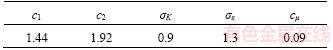
where GK=��T( uj/xi+ui/xj)(uj/xi); ��e=��0+��T, and ��T=c����K2/��; c1 is a constant related to the K�C�� equation; c2 is a constant related to the K�C�� equation; c�� is a constant related to the K�C�� equation; K is turbulent kinetic energy; vx is air velocity vectors in x direction, m��s�C1; vy is air of velocity vectors in y direction, m��s�C1; vz is air of velocity vectors in z direction, m��s�C1; ui is air velocity vx, vy and vz in x, y and z directions when i=x, y, z respectively; uj is air velocity vx, vy and vz in x, y and z directions when j=x, y, z respectively; xi is x, y and z directions when i=x, y, z respectively; xj is x, y and z directions when j=x, y, z respectively; �� is density of the air, kg��m�C3; �� is time, s; �� is dissipation rate of the turbulent kinetic energy; �� is dynamic viscosity of fluid, Pa��s; ��0 is viscosity coefficient of air molecules, Pa��s; ��e is air viscosity dynamic, Pa��s; ��K is effective Prandtl number of the turbulent kinetic energy; ���� is effective Prandtl number of dissipation rate of turbulent kinetic energy.
The constants involved in the mathematical model are shown in Table1.
Table1 Constant of model
2.2 Simulation physical model of air and concentrator
The three-dimensional model of dish solar power system specifically is shown in Figure 1. As shown in Figure 1, the heat receiver 1 can transform thermal energy into mechanical energy and then into electrical energy; cantilever beam 2 is mainly used to support the Stirling generator; concentrator 3 is mainly used for reflecting the incident solar radiation to the Stirling generator at the focus point. The main role of the stent 4 is to support the concentrator plate and the above boom and the Stirling engine, and to achieve the correct assembly of the base; counterbalance 5 is mainly used to achieve torque balance with the cantilever and generator; the weight counterbalancing pieces 6 is mainly used for balancing the weight of concentrator, heat receiver and stent; base 7 is mainly used for supporting and fixing.
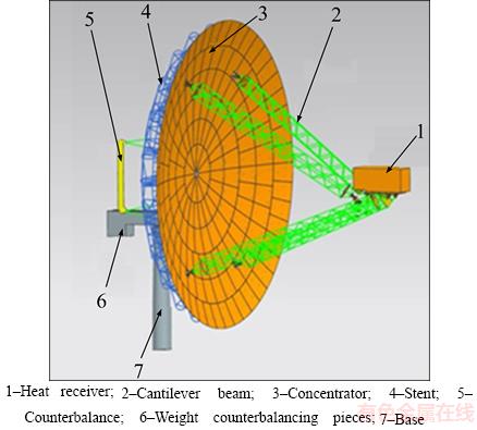
Figure 1 Three-dimensional physical model of solar thermal power generation system:
Considering that solar concentrator is in the atmospheric boundary layer, the concentrator will be in a fully open flow wind field when the wind flows around on the concentrator. The effects of wind on the concentrator will be beginning to take effect in a certain range, so a three-dimensional computational domain and its corresponding actual boundary conditions are required to be given in the numerical simulation. Obviously, a large fluid computational domain means a large number of cells that will lead to a large calculation amount and long calculation time. And a sufficient flow development will cause the distortion of the numerical simulation results when the fluid computational domain is too small. Therefore, it is important to delineate the proper fluid computational domain for reducing the calculation time and ensuring the accuracy of the calculation. The diameter of the concentrator model is 17 m and its thickness is 0.27 m, the length of fluid computational domain is about 10 times concentrator size and the width and height of fluid computational domain are about 5 times concentrator size in order to ensure the fully developed flow state in the fluid computational domain. After several modeling and simulation are done, the size of the fluid computational domain is determined as: 170 m��80 m��80 m; the height of center of the model is 10 m from the ground; the inlet air is 55 m from the center of the developed computational model which is shown in Figure 2 when concentrator elevation angle ��=0��, azimuth angle ��=0��.
Before generating the volume mesh, the dense volume mesh should be added according to the actual situation. Therefore, the calculation accuracy of the local position of the calculation model can be ensured by increasing the number of the volume meshes. The division mode of cascading dense volume mesh is adopted in the fluid computational domain. As shown in Figure 3, in order to maintain the certain continuity, the area of the dense volume mesh is divided into three parts that their dense intensities are gradually increased from far and near. Moreover, the dense volume mesh of the concentrator model is separately added to ensure the volume mesh quality of calculation domain. Finally, the polyhedral grids that are of good flexibility and adaptability are adopted in the fluid computational domain of the fluid computational model.
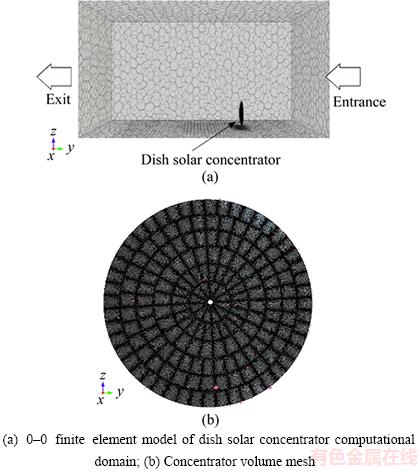
Figure 2 Finite element mesh model:
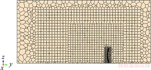
Figure 3 Middle cross-section of computational domain volume mesh
2.3 Simulation conditions of fluid�Csolid interaction field
In this work, the computational fluid dynamics (CFD) models are calculated by ANSYS fluent 14.5 and Tecplot 360 is used for post-processing. The setting of the fluid computational domain should be done before the settings of the fluid�Csolid interaction field boundary condition are given as follows: 1) A static steady-state analysis physical model is chosen, the air is selected as the fluid in fluid computational domain and its density is taken as a constant (namely ��=1.18415 kg/m3); 2) The turbulence model is set by the standard K-Epsilon model; 3) The air at ambient temperature is supposed adiabatic to solid field; 4) The reference pressure is 1.1325��105 Pa.
The segregated solver is used in the fluid computational domain due to the low flow air in the fluid computational domain. The initial and boundary conditions are set in the fluid computational domain as follows.
1) Initial and boundary conditions of inlet
The air of the fluid computational domain is taken as an incompressible fluid and the initial speed of the inlet is taken as a constant speed, namely the wind speeds are, respectively, 15, 18, 20, 22 and 25 m/s.
2) Boundary condition of the outlet
The boundary condition of the outlet is the pressure outlet, and the pressure of the outlet is set to a standard atmospheric pressure.
3) Wall conditions
The outer contour of the concentrator is circular and its radius is 8.42 m.The largest frontal gland projected area is 222.5102 m2. The boundary conditions of the bottom of fluid computational domain and the surfaces of the concentrator are set as wall. The roughness of the wall conditions is set as smooth. Moreover, the adhesion condition is used for the viscous fluid, which means that the air velocity at the wall is equal to the wall speed of the same wall position. Therefore, the wall with no slip condition is adopted because concentrator surface and the ground are fixed and the slip boundary condition is adopted at the top surface and the front and rear of the fluid computational domain.
2.4 Discrete and solving of control equation
The control equations of the wind load model for the dish solar concentrator are made discrete by finite difference method. According to the identified initial conditions and boundary conditions above, the SIMPLEST mind is adopted. The moment equation is made discrete, the pressure equation is solved by close-region, and the other conservation equations are solved by linear iterative method.
3 Results and discussion on flow field of dish solar concentrator based on virtual wind tunnel experiment with constant wind
3.1 Pressure distribution of dish solar concentrator
Pressure contours in the reflecting surface of the dish solar concentrator and the maximum pressure changes of the azimuth and elevation with different azimuth angle and velocity are shown respectively in Figures 4 and 5.
As shown in Figure 4, when the inlet velocity in dish solar concentrator computational domain is increased continuously from v=15 m/s to v=25 m/s, the maximum pressure pmax in dish solar concentrator will be increased from 221.28 Pa to 496.54 Pa, which means that the inlet velocity in dish solar concentrator computational domain plays an important role in the increase of the maximum pressure pmax of dish solar concentrator. Moreover, the pressure in the central region of dish solar concentrator is bigger than that away from the central region, which is due to wind focusing on the central region of the dish solar concentrator and detaching from the edge of the dish solar concentrator.
As shown in Figure 5, the pressure pmax of the reflective surface in the dish solar concentrator with different elevation angle is increased continuously from v=15 m/s to v=25 m/s, and the elevation angle �� plays an less important role in the increase of the maximum pressure pmax of the reflective surface in the dish solar concentrator with different azimuth angle �� when the inlet velocity v of the computational domain is of small value. The effect of elevation angle �� on the maximum pressure pmax of the reflective surface in the dish solar concentrator with different azimuth angles is gradually increased when the inlet velocity of computational domain is more than 22 m/s. When the elevation angle �� and the inlet velocity v of the computational domain are the same, the maximum pressure pmax of the reflective surface in the dish solar concentrator at azimuth angle ��=90�� is the maximum because there are bigger normal wind loads on the dish solar concentrator at azimuth angle ��=90��, and the maximum pressure pmax of the reflective surface in the dish solar concentrator at azimuth angle ��=135�� is the minimum because there are smaller normal wind loads on the dish solar concentrator at azimuth angle ��=135��.
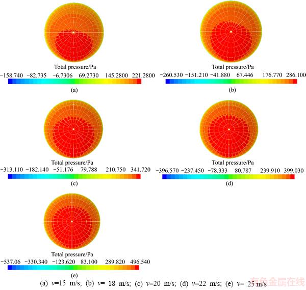
Figure 4 Pressure distribution of regular reflection surface in 0�C0 concentrator at different wind speeds:
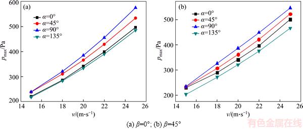
Figure 5 Maximum pressure change of reflective surface in dish solar concentrator with different azimuth angles and velocities:
Pressure distribution of condensor with different azimuth angles when v =15 m/s and ��=0�� and the maximum pressure change of reflective surface in the concentrator with different wind velocities are shown in Figures 6 and 7. As shown in Figure 6, the pressure distribution of the dish solar concentrator is obviously different under different poses. When v=15 m/s and ��=0��, wind loads focus on the central region in the dish solar concentrator and detachment appears at the edge of the dish solar concentrator due to wind loads acting on the reflective surface of the solar concentrator. Therefore, the pressure values of central region in the dish solar concentrator are bigger than those away from the central region in the dish solar concentrator. As shown in Figure 7, when v=15 m/s, the maximum pressure of the reflective surface in the dish solar concentrator increases from 221.26 Pa to 239.15 Pa with the change of the azimuth angle from ��=0�� to ��=90�� and then it decreases to 218.25 Pa at ��=135��. Moreover, the increase of elevation angle �� also causes a decline in the maximum pressure pmax of the reflective surface in the dish solar concentrator and the maximum pressure pmax of the reflective surface in the dish solar concentrator increases with the increase of the inlet velocity v of the computational domain. Therefore, the stiffness of the central region in the dish solar concentrator should be relatively raised.
3.2 Velocity distribution of dish solar concentrator
1) ��=0�� and ��=0��
The velocity distribution of the fluid domain in the dish solar concentrator when ��=0��, ��=0�� and v=25 m/s is shown in Figure 8.
As shown in Figure 8, the surface velocity of the dish solar concentrator is lower and its velocity direction is radial outward along the disc solar concentrator. The velocity of the dish solar concentrator is increased when the constant wind flows from the edge and gap of the dish solar concentrator. The low velocity area is formed on front surface of the dish solar concentrator and two vortex areas appear on rear surface of the dish solar concentrator, which is mainly due to formed Karman��s vortex street by the hindering phenomena of the dish solar concentrator.
2) ��= 0�� and ��=45��
The velocity distribution of fluid domain when ��=0�� and ��=45�� is shown in Figure 9. As shown in Figure 9(a), when v=15 m/s, a large recirculation zone formed on rear surface of the dish solar concentrator will cause the wind loads on the rear surface counteracted by the wind loads on the front surface. In addition, the wind outflow velocity increases through the rear surface gap of the dish solar concentrator, and the velocity direction of the wind in the upper and lower ends of the dish solar concentrator is out of the center and the velocity of the wind in the lower is bigger than that in the upper. Figures 9(b) and 9(c) show that the velocity distribution of the xy profile on the dish solar concentrator is substantially the same and the values are different when the wind speed increases to a constant v=20 m/s and v=25 m/s. The wind velocity through the gap of the dish solar concentrator will increase and the wind through the area of the dish solar concentrator will lead to the increase of the fluid velocity in upper and lower ends of the dish solar concentrator and the formation of two vortex areas on rear surface of the dish solar concentrator. The two vortex areas are larger and clearer than those when ��=0�� and ��=0��.
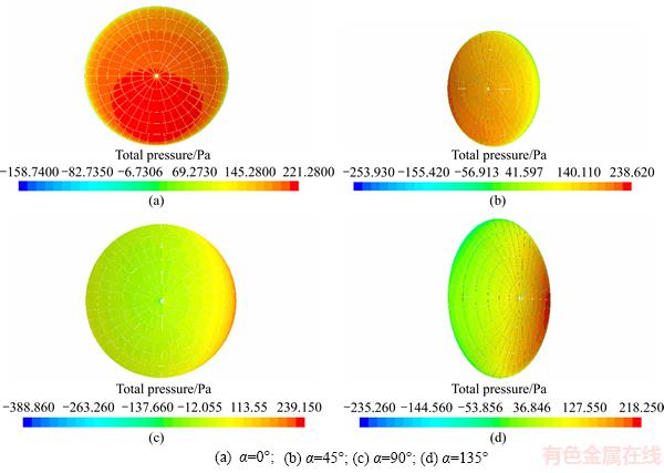
Figure 6 Pressure distribution of condensor with different azimuth angles when v =15 m/s and ��=0��:
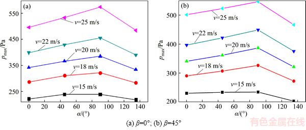
Figure 7 Maximum pressure change of reflective surface in concentrator with different wind velocities at azimuth angle:
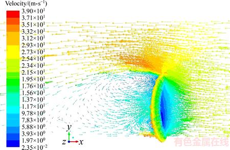
Figure 8 Velocity distribution of fluid domain in dish solar concentrator when �� =0��, �� =0�� and v=25 m/s
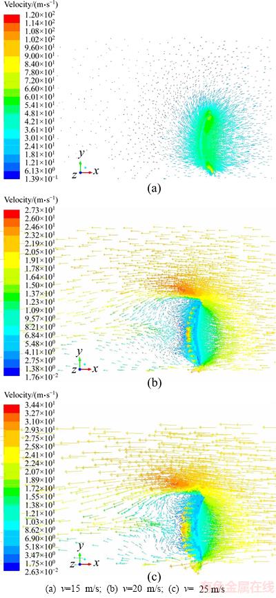
Figure 9 Velocity distribution of fluid domain when ��=0�� and ��=45��:
3) ��=0�� and ��=180��
The velocity distribution of fluid domain in the dish solar concentrator when ��=0�� and ��=180�� is shown in Figure 10. As shown in Figure 10, the flow velocity in front and rear surface of the dish solar concentrator is close to 0 m/s. And there are two vortexes on the front surface of the dish solar concentrator. It is concluded that the two vortex flow fields are more obvious than those when ��=0��. Considering that the vortexes of the front surface of the dish solar concentrator are stronger than those in the rear surface; therefore, the wind loads of the dish solar concentrator will be larger when ��=0�� and ��=180��.
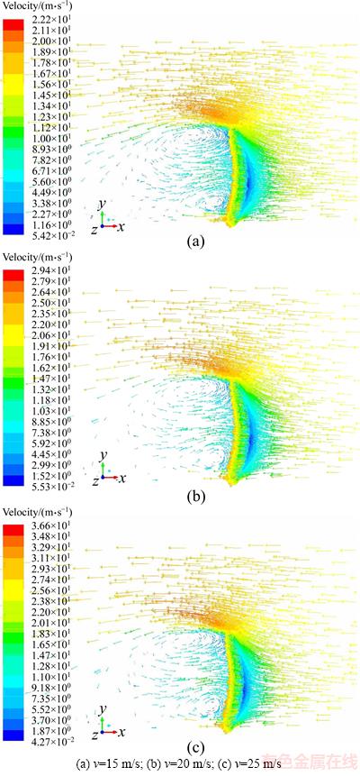
Figure 10 Velocity vector of fluid domain when ��=0�� and ��=180��:
4) ��=45�� and ��=0��
The velocity distribution of fluid domain in the dish solar concentrator when ��=45�� and ��=0�� is shown in Figure 11. Obviously, there is not the vortex area of fluid domain in the dish solar concentrator. The flow velocity from the edge and gap of the dish solar concentrator is increased and there is a maximum flow velocity in front surface lower end of the dish solar concentrator. Moreover, there is a small piece of the low-speed region due to the flow field change on the rear surface. In a word, there is the similar velocity distribution of fluid domain in the dish solar concentrator when ��=45��and ��=0�� and the velocity of fluid domain is increased with the increase of the inlet velocity of the dish solar concentrator fluid domain.
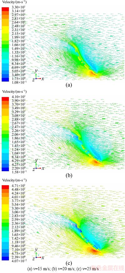
Figure 11 Velocity distribution of fluid domain when ��=45�� and ��=0��:
The above results show that: 1) when ��=0��, there are two vortex areas near the surface of the dish solar concentrator along flow direction of the inverse constant wind so that these vortex areas are increased significantly with the increase of the azimuth ��, but the formation of the two vortex areas has no relationship with the constant wind speed.2) When ��=45��, there is not the vortex area in the entire dish solar concentrator fluid domain. But there is a maximum flow velocity on lower end of the front surface in the dish solar concentrator, and then the overall velocity on the rear surface is increased with the increase of the inlet velocity of the fluid domain in the dish solar concentrator.
4 Conclusions
1) The different poses of the dish solar concentrator will lead to the different pressure distribution of the reflecting surface in the dish solar concentrator. There is bigger total pressure of the reflecting surface in the dish solar concentrator that is close to the direction of the flow and there is smaller total pressure of the reflecting surface in the dish solar concentrator that is away from the direction of the flow. Moreover, the maximum pressure pmax of the reflective surface in the dish solar concentrator increases with the increase of the inlet velocity of the computational domain. Therefore, the stiffness of the central region in the dish solar concentrator should be relatively raised.
2) The different poses of the dish solar concentrator will lead to the different velocity distribution of the reflecting surface in the dish solar concentrator. When ��=0��, two vortex areas are increased significantly with the increase of the azimuth ��. When ��=45��, the overall velocity on the rear surface is increased with the increase of the inlet velocity of the fluid domain in the dish solar concentrator.
References
[1] ZHANG Bin, E Jia-qiang, GONG Jin-ke, YUAN Wen-hua, ZUO Wei, LI Yu, FU Jun. Multidisciplinary design optimization of the diesel particulate filter in the composite regeneration process [J]. Applied Energy, 2016, 181: 14�C28.
[2] E Jia-qiang, ZHANG Zhi-qing, TU Zheng-fang, ZUO Wei, HU Wen-hua, HAN Dan-dan, JIN Yu. Effect analysis on flow and boiling heat transfer performance of cooling water-jacket of bearing in the gasoline engine turbocharger [J]. Applied Thermal Engineering, 2018, 130: 754�C766.
[3] DENG Yuan-wang, LIU Hua-wei, ZHAO Xiao-huan, E Jia-qiang, CHEN Jian-mei. Effects of cold start control strategy on cold start performance of the diesel engine based on a comprehensive preheat diesel engine model [J]. Applied Energy, 2018, 210: 279�C287.
[4] LIU Teng, E Jia-qiang, YANG Wen-ming, HUI An, CAI Hao. Development of a skeletal mechanism for biodiesel blend surrogates with varying fatty acid methyl esters proportion [J]. Applied Energy, 2016, 162: 278�C288.
[5] E Jia-qiang, LIU Teng, YANG Wen-ming, LI Jing, GONG Jin-ke, DENG Yuan-wang. Effects of fatty acid methyl esters proportion on combustion and emission characteristics of a biodiesel fueled diesel engine [J]. Energy Conversion & Management, 2016, 117: 410�C419.
[6] E Jia-qiang, PHAM M H, ZHAO Dan, DENG Yuan-wang, LE D H, ZUO Wei, ZHU Hao, LIU Teng, PENG Qing-guo, ZHANG Zhi-qing. Effect of different technologies on combustion and emissions of the diesel engine fueled with biodiesel: A review [J]. Renewable & Sustainable Energy Reviews 2017, 80: 620�C647.
[7] CHEN Bo, SHI Zhang-ming, JIANG Shao-jian, TIAN Hong. Mechanism studies of 5-HMF pyrolysis by quantum chemistry [J]. Journal of Central South University, 2017, 24(11): 2565-2571.
[8] SARDESHPANDE V R, CHANDAK A G, PILLAI I R. Procedure for thermal performance evaluation of steam generating point-focus solar concentrators [J]. Solar Energy, 2011, 85(7): 1390�C1398.
[9] LI Lu, SUN Jie, LI Yin-shi. Thermal load and bending analysis of heat collection element of direct-steam- generation parabolic-trough solar power plant [J]. Applied Thermal Engineering, 2017, 127: 1530�C1542.
[10] GUPTA M K, KAUSHIK S C, RANJAN K R, PANWAR N L, REDDY V S, TYAGI S K. Thermodynamic performance evaluation of solar and other thermal power generation systems: A review [J]. Renewable and Sustainable Energy Reviews, 2015, 50: 567�C582.
[11] NI Ming-jiang, YANG Tian-feng, XIAO Gang, NI Dong, ZHOU Xin, LIU Huan-lei, SULTAN U, CHEN Jin-li, LUO Zhong-yang, CEN Ke-fa. Thermodynamic analysis of a gas turbine cycle combined with fuel reforming for solar thermal power generation [J]. Energy, 2017, 137: 20�C30.
[12] PUROHIT I, PUROHIT P. Technical and economic potential of concentrating solar thermal power generation in India [J]. Renewable and Sustainable Energy Reviews, 2017, 78: 648�C667.
[13] KUMAR P, DUTTA P, MURTHY S S, SRINIVASAN K. Solar driven carbon dioxide Brayton cycle power generation with thermal compression [J]. Applied Thermal Engineering, 2016, 109: 854�C860.
[14] OMER S A, INFIELD D G. Design and thermal analysis of a two stage solar concentrator for combined heat and thermoelectric power generation [J]. Energy Conversion and Management, 2000, 41(7): 737�C756.
[15] KALOGIROU S A. Solar thermal collectors and applications [J]. Progress in Energy and Combustion Science, 2004, 30(3): 231�C295.
[16] KUMAR N S, REDDY K S. Comparison of receivers for solar dish collectors system [J]. Energy Conversion and Management, 2008, 49(4): 812�C819.
[17] CHRISTO F C. Numerical modelling of wind and dust patterns around a full-scale paraboloidal solar dish original research article [J]. Renewable Energy, 2012, 39(1): 356�C366.
[18] AGNENI A, COPPOTELLI G, GRAPPASONNI C. A method for the harmonic removal in operational modal analysis of rotating blades [J]. Mechanical Systems and Signal Processing, 2012, 27: 604�C618.
[19] WU S Y, XIAO L, CAO Y D, LI Y R. Convection heat loss from cavity receiver in parabolic dish solar thermal power system: A review [J]. Solar Energy, 2010, 84(8): 1342�C1355.
[20] REDDY K S, KUMAR S N. Combined laminar natural convection and surface radiation heat transfer in a modified cavity receiver of solar parabolic dish [J]. International Journal of Thermal Science, 2008, 47(12): 1647�C1657.
[21] KUMAR S N, REDDY K S. Numerical investigation of natural convection heat loss in modified cavity receiver for fuzzy focal solar dish concentrator [J]. Solar Energy, 2007, 81(7): 846�C855.
[22] ZANGANEH G, BADER R, PEDRETTI A. A solar dish concentrator based on ellipsoidal polyester membrane facets [J]. Solar Energy, 2012, 86(1): 40�C47.
[23] XIAO Jun, WEI Xiu-dong, LU Zhen-wu, YU Wei-xing, WU Hong-sheng. A review of available methods for surface shape measurement of solar concentrator in solar thermal power applications [J]. Renewable and Sustainable Energy Reviews, 2012, 16(5): 2539�C2544.
[24] HERNANDEZ N, RIVEROS-ROSAS D, VENEGAS E, DORANTES R J, ROJAS-MORIN A, JARAMILLO O A, ARANCIBIA-BULNES C A, ESTRADA C A. Conical receiver for a paraboloidal concentrator with large rim angle [J]. Solar Energy, 2012, 86(4):1053�C1062.
[25] RUELAS J, VEL ZQUEZ N, CEREZO J. A mathematical model to develop a Scheffler-type solar concentrator coupled with a Stirling engine [J]. Applied Energy, 2013, 101(1): 253�C260.
(Edited by YANG Hua)
���ĵ���
���ں��������綴ʵ���²�ͬ��̬�ͷ��ٶԵ�ʽ̫���ܾ۹���������Ӱ���о�
ժҪ��Ϊ����ߵ�ʽ̫���۹����Ľṹ���ܣ����ڸ߾�����ֵ�㷨�����˵�ʽ̫���ܾ۹�����άģ�ͣ������ú��������綴ʵ���о��˲�ͬ��̬�ͷ��ٷֲ��µ�ʽ̫���ܾ۹����������ѹ���ֲ�������������ٷֲ�������õ��˵�ʽ̫���ܾ۹���ǰ�����ķ�ѹ�ֲ�������������ķ��غ��ٶȷֲ��͵�ʽ̫���ܾ۹��������Ĵ��ĸն�Ӧ�ʵ���ߵ���ؽ�������о������Ϊ��ʽ̫���ܾ۹����ṹ���ܸ��ƺ���ʵ���еĹ�������ṩ�������ݡ�
�ؼ��ʣ��۹�����������ϣ�ѹ���ֲ������ٷֲ�������綴ʵ��
Foundation item: Projects(201208430262, 201306130031) supported by the China Scholarship Council
Received date: 2017-06-18; Accepted date: 2017-12-27
Corresponding author: E Jia-qiang, PhD, Professor; Tel: +86�C731�C88821750; E-mail: ejiaqiang@hnu.edu.cn: ORCID: 0000-0002- 2820-0472
Abstract: In order to improve structure performance of the dish solar concentrator, a three-dimensional model of dish solar concentrator was established based on the high-precision numerical algorithms. And a virtual wind tunnel experiment with constant wind is adopted to investigate the pressure distribution of the reflective surface, velocity distribution of the fluid domain for the dish solar concentrator in different poses and wind speeds distribution. Some results about wind pressure distribution before and after dish solar concentrator surface and wind load velocity distribution in the entire fluid domain had been obtained. In particular, it is necessary to point out that the stiffness at the center of the dish solar concentrator should be relatively raised. The results can provide a theoretical basis for the improvement of solar concentrator dish structure as well as the failure analysis of dish solar concentrator in engineering practice.
