
Trans. Nonferrous Met. Soc. China 22(2012) s280-s286
Mechanics condition of thin-walled tubular component with rib hydroforming
CHU Guan-nan1,2, YANG Shuai3, WANG Jian-xun2
1. State Key Laboratory of Advanced Welding and Joining, Harbin Institute of Technology, Harbin 150001, China;
2. School of Naval Architecture, Harbin Institute of Technology at Weihai, Weihai 264209, China;
3. Tianjin Aerospace Electromechanical Equipment Research Institute, Tianjin 300450, China
Received 28 August 2012; accepted 25 October 2012
Abstract:
To explore the hydroforming possibility of thin-walled tubular component with rib, mechanical analysis and finite element analysis (FEA) were conducted to investigate the rib buckling mechanics conditions. Based on lath-beam assumption, buckling Euler force was derived for rib which is restrained at one end and free at the other. The results indicate that it is possible to achieve a sound thin-walled tubular with rib component through hydroforming process and its expiation ratio can reach 20%. According to FEA, the effects of rib height and inner radius on buckling degree were studied and the threshold values of both rib height and inner radius were given. Simulation results indicate that there is a certain value for buckling and the threshold values of rib height and inner radius to thickness are 14 and 30. The formability deteriorates as rib height and rib inner radius increase. At last, the hydroforming limit diagram was drawn for hydroforming thin-walled tubular component with rib of 1Cr18Ni9. The results are useful for further study of hydroforming regularity of thin-walled tubular component with rib.
Key words:
thin-walled and height-rib component; tubular component; hydroforming; mechanics condition; integral forming; buckling;
1 Introduction
With the continuous improvement of high-speed and high-maneuverable flight vehicle, higher and higher demands are proposed on light-weight and long-life performances of structure components. As a result, internal components are more and more widely used in modern flight vehicle design [1-4]. Thin-walled tubular component with rib is a typically component of such kind structure [5-7]. Up till now, for manufacture of thin-walled tubular component with rib, the forming process is usually as main body forming-rib forming-welding, namely, main-body and rib were specially formed and then welded together [8,9]. Such forming process would induce seriously welding wrinkle, which led to worse shape precision and lower reliability [10-12], especially for the ultrathin wall hollow components [13,14]. It was found that uniformity of welding residual stress is the key factor for crack growth under cyclic loading. BIAN et al [15] and LI et al [16] studied the effects of welding residual stress systematically and its result shows transverse weld-seam, i.e. the direction of weld-seam perpendicular to the direction of first stress, reduces the fatigue life by 20%-40%. As a result, transverse weld-seam is not recommended for aeronautical structure. What��s more, the development of modern weapons is also demanding integral component to replace welding or riveting structure. In view of the forming situations above, a new process of main body and rib integral forming was proposed to solve the inherent difficulties during conventional forming process.
In this work, the mechanics condition and process diagram were studied for thin-walled tubular component with rib hydroforming based on mechanical analysis and FEA. At last, according to the effects of rib height and inner radius on buckling degree, the hydroforming limit diagram of thin-walled tubular component with rib was given.
2 Method selection of buckling calculation
In view of thin-walled tubular component with rib hydroforming shown in Fig. 1, the key problem to achieve a sound component is whether the rib could be expanded successfully without buckling. The mechanics condition is analyzed.
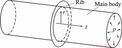
Fig. 1 Schematic diagram of thin-walled tubular component with rib hydroforming
Under internal pressure, force analyses of both main body and rib are shown in Fig. 2. It can be seen only a uniform pressure Q acting on the in-circled edge of rib and improves continuously as expansion ratio of main body increasing. Thus, rib has trend to buckling with deformation going on, if the height of rib extends to some degree. If buckling happens, it can be divided into two types according to its happening stage. The first is buckling happened while rib is at elastic deformation stage, and such shape rib cannot be used to hydroforming. The second is buckling happened after rib experienced certain degree of plastic expansion. Therefore, the plastic expansion ability before buckling can be used to hydroforming. As a result, internal hydroforming ability of thin-wall tubular component with rib improves as the rib plastic expansion degree before buckling. Thus, the relation between ribs buckling Euler force and yield stress is the key to assess if it has plastic expansion ability.
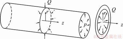
Fig. 2 Schematic diagram of force analysis of main body and rib
For ease of following presentation, build columniation coordinate system is shown in Fig. 2. The rib is restrained at in-circled border and free at the other according to the actual geometrical structure characteristics. Consequently, under such kinds of restrain and loading, forms of instability of rib could only be unidirectional bending according to plate instability theory. Unidirectional bending means there is curvature along r direction but no curvature along �� direction on r-�� plane, and bending shape is only half-wave as shown in Fig. 3. If blank initial shape is axial symmetry, force conditions of all particles on circle of r=a (a��[rin, rout], where, rin is inner radius of rib, rout is outer radius of rib) are just the same. At the same time, radii of all particles on circle of r=a are just the same.
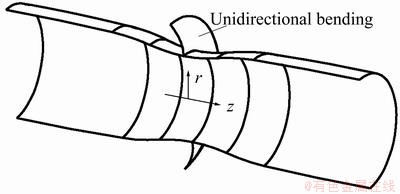
Fig. 3 Bending shape of rib
Fundamental assumptions:
1) Direct normal assumption: the normal line perpendicular to mid-plane is still straight line after buckled, and the distance of particles on normal keeps unvaried before and after deformation.
2) Thickness stress is far smaller than other stress, i.e., ��t��0.
3) Neglect the deformation of mid-plane.
Based on the above assumptions and according to plate instability theory, following conclusions are derived. In view of unidirectional bending, Euler force is just determined by materials�� elastic modulus, plane height and plane thickness, and is not concerned with plane width and width direction stress. That means Euler force of plane can be calculated based on lath-beam assumption. Thus, the Euler force of rib shown in Fig. 1 can be calculated by analyzing the buckling Euler force of lath-beam L as shown in Fig. 4.
3 Calculation of buckling Euler force
According to imaginary displacement principle, assuming the deflection of lath-beam L is ��(y) when it is in different equilibrium. Then apply an imaginary displacement �Ħ�(y) on the lath-beam L. Thus, if ��(y) is an equilibrium stage, then ��VL=��WL, where ��VL is virtual strain energy, ��WL is external virtual work, VL and WL are strain energy and external work of lath-beam L while it is deformed from initial place to bending place (shown in Fig. 4(e)) respectively.
 (1)
(1)
where T is external force.
Because external force T keeps unchanged, the relation between UL and WL can be described as UL=WL.

Fig. 4 Schematic diagram of force analysis of lath-beam L
According to the geometric relationship as shown in Fig. 4(e),
 (2)
(2)
Because �� is quite small, sin2(��/2)=(��/2)2, and  , thus,
 (3)
(3)
And external work WL can be derived as
 (4)
(4)
For lath restrained at one end and free at the other, its flexural functions is fitted as
 (5)
(5)
Combining Eqs. (5) and (1), strain energy VL can be derived as

 (6)
(6)
Combining Eqs. (5) and (4), external work UL can be derived as

 (7)
(7)
For ring-shaped rib, deformation along hoop direction also happens during buckling bending. For elastic deformation stage, hoop strain ���� and radius strain ��r can be expressed as follows:
 (8)
(8)
According to principle of force equilibrium, hoop stress ���� and radius stress ��r can be described as
 (9)
(9)
Combining Eqs. (8) and (9), the relation between hoop strain ���� and radius strain ��r can be described as
 (10)
(10)
Because the principal stress axes keep unvaried, d��L�� can be described as[17]
 (11)
(11)
Then strain energy VL�� and external work UL�� along hoop direction can be derived by combining Eqs. (6), (7) and (10). But, the functions of strain energy and external work are nonsoluble if it still uses the flexural function as Eq. (5).
To achieve a mathematical expression, flexural function is simplified as Eq. (12) for energy VL�� and external work UL�� analysis.
 (12)
(12)
Combining Eqs. (1), (4), (10) and (11), the strain energy VL�� and external work UL�� along hoop direction can be derived as follows:

 (13)
(13)

 (14)
(14)
Combining Eqs. (6) and (13), the total strain energy V is derived as

 (15)
(15)
Combining Eqs. (7) and (14), the total external work U is derived as

 (16)
(16)
Thus, the total routine can be given as follows:
 (17)
(17)
According to the variational principle, the requirement of functional taking stationary value is the first variation of functional ��=V-U equal to zero. Thus, virtual displacement can be expressed as
 (18)
(18)
Combining Eqs. (15), (16) and (18), the first variation of functional ��=V-U is described as


 (19)
(19)
Due to a1��0, buckling Euler force qE is derived as


 (20)
(20)
If p0 is the initial pressure of rib hydrobulging, conclusions can be obtained as follows:
If qE��p0, the rib has no ability to hydroforming.
If qE>p0, the rib has ability to hydroforming.
4 FEA of rib buckling
4.1 Finite element model
AbaqusTM is used to simulate the expand process of rib restrained at one end and free at the other. A quarter of a plane strain model is analyzed according to the symmetrical profile. Rib is meshed by 3D-shell element S4R and the FEM modal is shown in Fig. 5. Two boundary conditions were carried out. Symmetric constrains were applied on both lines of ��=0 and ��=90��. R and �� rotation constrains were applied on rib in-circled edge to simulate the tie boundary conditions between main body and rib. An initial deflection on out-circled edge is applied to inducing plate buckling bending.
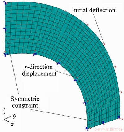
Fig. 5 Finite element model
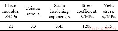
The rib blank is a stainless steel (0Cr18Ni9Ti) with an original thickness of 2 mm and is assumed as elastic-plastic strain hardening material and the material properties are shown in Table 1.
Table 1 Parameters of materials
4.2 Buckling process
Figure 6 shows the deformed shapes of rib in different stages, whose inner radius is 60 mm and ratio of rib height to thickness, described by h/t, is 14 and 15. It can be seen that rib plate is steady for rib with h/t<14, when displacement of inner edge is less than 20%rin. In view of rib with h/t>15, rib induces overall buckling when displacement of inner edge reaches 20%rin. It can be concluded that rib restrained at one end and free at the other end expresses some degree of plastic expansion ability if ratio h/t is among a certain degree. Thus, such rib could be hydroformed.
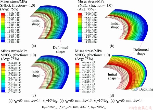
Fig. 6 Shape of rib after expansion
4.3 Effect of rib height
In this work, z-direction displacement, named as dz, was selected to quantitatively describe buckling degree, and the measurement method of dz is shown in Fig. 7.
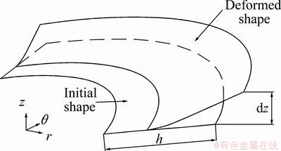
Fig. 7 Schematic diagram of z-direction displacement
Figure 8 shows the effect of rib height on buckling degree. It can be seen that there is a certain threshold value of rib height to induce buckling happening. Buckling happens only when rib height reaches the threshold value, and buckling level aggravates rapidly as rib height. As shown in Fig. 8, dz is always zero when h/t is less than 14, which means that rib can be expanded successfully if h/t is less than 14. When h/t reaches 14, a negligible amount of dz happens, which is about 0.26 mm. But dz increases rapidly to 7.5 mm during h/t increased by 1 reaching to 15. It is worthwhile to note that obviously buckling bending can be observed under this displacement level as shown in Fig. 6. After h/t increases to 18, dz increases slowly. Thus, it can be concluded that the threshold value is 14 for rib height to induce buckling.
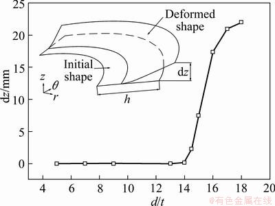
Fig. 8 Effect of rib height
4.4 Effect of rib inner radius
Figure 9 shows the effect of rib height on buckling degree. It can be seen that dz decreases rapidly when rib inner radius is less than 65 mm, but is gradually tending to zero after rib inner radius is larger than 75 mm, which means there is not a obvious threshold value of rib inner radius to induce buckling happening. As shown in Fig. 9, dz is about 7.6 mm when inner radius is 60 mm, and decreases to 1.3 mm when inner radius is 65 mm. When rib inner radius reaches 70 mm, z-direction displacement is always 0.25 mm. Under this deformation level, buckling bending still can be observed. Only when rib inner radius is larger than 75 mm, dz decreases to smaller than 0.02 mm. For such displacement level, it can be concluded that the threshold value is 75 for rib inner radius to induce buckling.
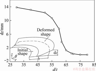
Fig. 9 Effect of initial inner radius
4.5 Forming limit diagram
Comprehensive simulations were conducted to investigate the influence of inner radius and ratio of rib height to thickness. Failure modes are located with the aid of process diagram as shown in Fig. 10, where SOU Com and BUC Def denote no buckling bending and buckling bending, respectively. It can be seen that, for an inner radius rib, buckling bending occurs only when h/t exceeds some degree. For rib with certain ratio h/t, buckling bending does not occur if inner radius reaches some degree. Consequently, integral hydroforming is possible for thin-walled tubular component if rib is among proper geometric structure.

Fig. 10 Process diagram
5 Conclusions
1) Based on lath-beam assumption, buckling Euler force is derived for thin-walled tubular component with rib internal hydroforming. Mechanical analysis proves that it is practical for tubular component with rib hydrobulging. The mechanical boundary condition is that rib initial yield pressure is larger than rib buckling Euler force. The geometry boundary condition is that rib height is less than and rib inner radius is larger than the threshold value.
2) Rib restrained at one end and free at the other end has hydrobulging ability. Expansion ratio can reach 20% for 1Cr18Ni9Ti blank when ratio of rib height to thickness is less than 14 and the threshold values of rib height and inner radius to thickness are 14 and 30, respectively.
3) For thin-walled tubular component with rib, trend of buckling bending increases with the increase of ratio of rib height to thickness and decreases with the increase of inner radius. Thin-walled tubular component with rib can be hydroformed successfully only when rib height is less than that of threshold values and at the same time rib inner radius is larger than that of threshold values.
References
[1] HYAE K, YI H S, YIM G Y, LEE S M, LEE G S, CHUNG Y H. Experimental investigation of friction coefficient in tube hydroforming [J]. Transactions of Nonferrous Metals Society of China, 2011, 21(1): 194-198.
[2] YAN M H, WU X R, ZHU Z S. Recent progress and prospects for aeronautical material technologies [J]. Aeronautical Manufacturing Technology, 2003, (12): 19-25.
[3] CHEN Z G, CHEN Z T, WANG X H. Study on ribs elastic deformation in NC milling [J]. Mechanical Engineer, 2005(11): 34-36.
[4] WANG Z J, GAO T J. Inner and outer pressure forming of nickel based super-alloy thin-walled part with variable diameter sections [J]. Transactions of Nonferrous Metals Society of China, 2008, 18(2): 285-290.
[5] LIU J S, ZHANG S H, ZENG Y S, LI Z Q, REN L M. Simulation of incremental forming on integral panel skin with grid-type ribs [J]. Material Science and Technology, 2004, 12(5): 515-517.
[6] SHEN G S, DAVID F. Manufacturing of aerospace forgings [J]. J Mater Process Technol, 2000, 98: 189-195.
[7] LEE K S, SEO H K, YANG Y J, HWANG W C, KIM K H, YANG I Y. Collapse behavior evaluation of hybrid thin-walled member by stacking condition [J]. Transactions of Nonferrous Metals Society of China, 2011, 21(1): 135-140.
[8] CHU Guan-nan, LIU Gang, YUAN Shi-jian, LIU Wen-jian. Characteristics of thickness distribution of tailor-welded tube hydroforming [J]. J Cent South Univ Technol, 2011, 18(6): 1813-1818.
[9] CHU Guan-nan, LIU Gang, YUAN Shi-jian, LIU Wen-jian. Weld seam movement of tailor-welded tube during hydrobulging with dissimilar thickness [J]. Int J Adv Manuf Technol, 2012, 60(9): 1255-1260.
[10] ZHANG Gui-feng, SU Wei, ZHANG Jun, WEI Zhong-xin, ZHANG Jian-xun. Effects of shoulder on interfacial bonding during friction stir lap welding of aluminum thin sheets using tool without pin [J]. Transactions of Nonferrous Metals Society of China, 2010, 20(12): 2223-2228.
[11] ZHANG Zhen-xin. Deformation control of welding plane of stainless steel (316) thin plate [J]. Modern Welding Technology, 2008, 11: 36-37.
[12] FANG Zong-tao, SUN Bo, Li Chun-ren, GUAN You-geng, WANG Zhi-jian. Study progress of the control measures of welding deformation in thin plate [J]. Modern Welding Technology, 2011, 7: 20-22.
[13] LI Jing-yong, LI Biao-feng, FENG Gang-xian. Effect of weld geometrical features on fatigue properties of 5A30 aluminum [J]. Transactions of Nonferrous Metals Society of China, 2004, 14(11): 1895-1900.
[14] Bai Yan, Gao Hong-ming, Wu Lin. Influence of plasma-MIG welding parameters on aluminum weld porosity by orthogonal test [J]. Transactions of Nonferrous Metals Society of China, 2010, 20(8): 1392-1396.
[15] BIAN Ru-gang, CUI Wei-cheng, WAN Zheng-quan, LI Liang-bi, WANG Ming-wei. A quantitative study on the effect of welding residual stresses on fatigue life [J]. The Chinese Journal of Nonferrous Metals, 2011, 21(7): 776-783. (in Chinese)
[16] LI Jing-yong, LI Biao-feng, FENG Gang-xian. Effect of weld geometrical features on fatigue properties of 5A30 aluminum alloy welded joints [J]. The Chinese Journal of Nonferrous Metals, 2004, 14(11): 1895-1900. (in Chinese)
[17] WANG Z R. A consistent relationship between the stress-and-strain-components and its applications for analyzing the plane-stress forming process [J]. J Mater Process Technol, 1995, 55: 1-4.
���ڸ߽�Ͳ�μ��ڸ�ѹ������ѧ��������
������1,2, �� ˧3, ����ѫ2
1. ��������ҵ��ѧ �Ƚ����������ӹ����ص�ʵ���ң������� 150001��
2. ��������ҵ��ѧ(����) �����뺣��ѧԺ������ 264209��
3. ���������豸�о�������� 300450
ժ Ҫ��Ϊ̽�ֱ��ڸ߽�Ͳ�μ������ڸ�ѹ���εĿ����ԣ�������ѧ��������ֵģ�����ϵķ������о���һ��Լ����һ������Լ�������ı���(��ǿ��)ʧ�ȵ���ѧ���������ڡ������������۸����˽��ʧ��ŷ��������ѧ����ʽ�������ֵģ������˽��߶Ⱥ��ھ���ʧ�ȵ�Ӱ�졣�������������1Cr18Ni9Ti���ڸ߽�Ͳ�μ�������Ϊ20%ʱ���ٽ�ߺ�Ⱥ;���ȷֱ�Ϊ14��30�����Ÿߺ���������Խ��ͣ����ž��������������ߡ��������ڸ�ѹ���δ���ͼ��Ϊ���ڸ߽�Ͳ�μ��ڸ�ѹ���ι��ɵ������о����ڸ�ѹ���ι�����Ƶ춨�����ۻ�����
�ؼ��ʣ����ڸ߽����Ͳ�μ����ڸ�ѹ���Σ���ѧ������������Σ�ʧ��
(Edited by HE Yun-bin)
Foundation item: Project(51005054) supported by the National Natural Science Foundation of China; Project(20100471025) supported by the National Science Foundation for Post-doctoral Scientists of China; Project(HIT.NSRIF.2011112) supported by the Natural Scientific Research Innovation Foundation in Harbin Institute of Technology, China; Project(2011-3-96) supported by the Ministry of Science & Technology of Weihai, China
Corresponding author: CHU Guan-nan; Tel: +86-631-5687830; E-mail: chuguannan@163.com
DOI: 10.1016/S1003-6326(12)61720-8
Abstract: To explore the hydroforming possibility of thin-walled tubular component with rib, mechanical analysis and finite element analysis (FEA) were conducted to investigate the rib buckling mechanics conditions. Based on lath-beam assumption, buckling Euler force was derived for rib which is restrained at one end and free at the other. The results indicate that it is possible to achieve a sound thin-walled tubular with rib component through hydroforming process and its expiation ratio can reach 20%. According to FEA, the effects of rib height and inner radius on buckling degree were studied and the threshold values of both rib height and inner radius were given. Simulation results indicate that there is a certain value for buckling and the threshold values of rib height and inner radius to thickness are 14 and 30. The formability deteriorates as rib height and rib inner radius increase. At last, the hydroforming limit diagram was drawn for hydroforming thin-walled tubular component with rib of 1Cr18Ni9. The results are useful for further study of hydroforming regularity of thin-walled tubular component with rib.
