
J. Cent. South Univ. Technol. (2007)02-0243-05
DOI: 10.1007/s11771-007-0048-6 ![]()
Dynamic simulation on effect of flame arrangement on thermal process of regenerative reheating furnace
OU Jian-ping(ŷ��ƽ)1, MA Ai-chun(������)1, ZHAN Shu-hua(ղ����)2,
ZHOU Jie-min(������)1, XIAO Ze-qiang(����ǿ)1
(1. School of Energy Science and Engineering, Central South University, Changsha 410083, China;
2. General Iron and Steel Research Institute, Beijing 100081, China)
Abstract:
By analyzing the characteristics of combustion and billet heating process, a 3-D transient computer fluid dynamic simulation system based on commercial software CFX4.3 and some self-programmed codes were developed to simulate the thermal process in a continuous heating furnace using high temperature air combustion technology. The effects of different switching modes on injection entrancement of multi burners, combustion and billet heating process in furnace were analyzed numerically, and the computational results were compared with on-site measurement, which verified the practicability of this numerical simulation system. The results indicate that the flow pattern and distribution of temperature in regenerative reheating furnace with partial same-side-switching combustion mode are favorable to satisfy the high quality requirements of reheating, in which the terminal heating temperature of billets is more than 1 460 K and the temperature difference between two nodes is not more than 10 K. But since the surface average temperature of billets apart from heating zone is only about 1 350 K and continued heating is needed in soaking zone, the design and operation of current state are still needed to be optimized to improve the temperature schedule of billet heating. The distribution of velocity and temperature in regenerative reheating furnace with same-side-switching combustion mode cannot satisfy the even and fast heating process. The terminal heating temperature of billets is lower than that of the former case by 30 K. The distribution of flow and temperature can be improved by using cross-switching combustion mode, whose terminal temperature of billets is about 1 470 K with small temperature difference within 10 K.
Key words:
high temperature air combustion; reheating furnace; switched combustion; numerical simulation ��
1 Introduction
The reheating furnace is an important equipment of hot rolled steels for heating the billets to a needed temperature of high quality steels. The thermal process of steel-rolling heating furnace and billet heating process have been studied early, and a series of research findings were obtained, which promotes the development of numerical study on thermal process of steel-rolling heating furnace. Limited by the computation conditions, some important and complex problems were simplified, such as the billets in the furnace being treated to be motionless[1-4], ignoring the combustion[5-6], simplifying the 3-D process to be 1-D[7] or 2-D[8] process. In 1990s, the technology of High Temperature Air Combustion (HTAC) was applied to reheat furnace in Japan and a new type HTAC reheating furnace was developed[9-10]. In HTAC furnaces, burners are arranged on the sidewalls and act as combustors and exhausts alternatively. High-speed combustion current brings strong mixing, and the dominant direction of current is from one side to another with alternative switching. Because the initial jets and flames are vertical to the moving direction of billets, and the inlets and outlets of fluid change periodically, it is very difficult to simulate and control this new type reheating furnace. There are dozens of flame pairs in HTAC furnaces, and it is clear that different reversing combustion modes will cause different flows and temperature distributions, which will result in different billet heating effects. With the aim to optimize the combustion control of HTAC reheating furnaces, based on commercial CFD code CFX4.3, a numerical research on the effect of switching modes on the thermal process of a HTAC reheating furnace is carried out to study the effect of flame layouts on the flow and temperature fields. The research will help to improve greatly the simulating and control optimizing technology and to make a rapid progress in regenerative reheating furnaces.
2 Numerical simulation
2.1 Computational domain and grids
A HTAC heating furnace of a domestic 80 t/h plate mill, as shown in Fig.1, is studied. The air and gas are preheated simultaneously, and honeycomb ceramics are used as heat exchanger. The chamber and billet size are 27 000 mm��4 600 mm��3 000 mm and 2 000 mm�� 1 500 mm��200 mm, respectively. There are 38 pairs of burners arranged on the sidewalls and acted as combustors and exhausts alternatively. This furnace is divided into two combustion spaces by the closed arrangement of billets. On account of the dynamic heating process of billets and the large ratio of the dimension of furnace chamber to nozzles, the upper combustion chamber and the up half of the billets are considered the computational domain, and symmetrical boundary condition is used to save the memory and to accelerate the calculation. With Body Fitted Grids System(BFGS), the computational domain is divided by block structure grids with 434 826 non-uniform elements, as shown in Fig.2.
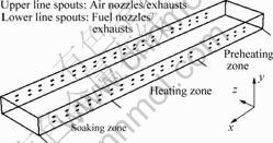
Fig.1 HTAC heating furnace for plate mill

Fig.2 Grids of calculated zone
(a) Width direction; (b) Length direction
In this paper, a transient numerical simulation by using CFX code in 3-D coordinate system, combined with fluid flow, combustion, and radiation heat transfer process, was performed. The complete heating process of billet in furnace is decomposed into many mobile heating and stable heating processes, and the temperature results of current iteration are set as the initial value for the next calculation when a billet��s width is added to the pushing distance.
2.2 Governing equations[11-15]
Continuity equation:
![]() (1)
(1)
Momentum equation:
 (2)
(2)
Energy equation:
![]() (3)
(3)
As to billets, heat-conducting equation is
![]() (4)
(4)
where ��f is the density of gas, U is the gas velocity, p is pressure, p�� is modified pressure, B is body force, H is total enthalpy, ��H is Prandtl number, cp,f is specific heat capacity of gas, ��f is heat conducting coefficient, ��eff is efficient viscidity of gas, Ts is the temperature of billet, ��s, cp,s, and ��s are billet��s density, specific heat capacity, and heat conducting coefficient, respectively.
2.3 Boundary conditions and initial conditions
On account of the on-site testing and producing statistics, the preheated temperatures of preheating zone, heating zone, and soaking zone are 1 180, 1 250, and 1 300 K respectively, and the gas flows through each burner of preheating zone, heating zone, and soaking zone are 280, 270, 245 Nm3/h respectively with excessive air coefficients of these zones being 1.36, 1.22, 1.10.
The environmental pressure and temperature are set to be 101 325 Pa and 310 K, and mixed gas with low heat value of 5 576 kJ/Nm3 is used as the fuel.
Heat-conducting solid boundary condition without inner heat source is used to simulate the inner heating process, and the blackness of billet surface and furnace wall is 0.8[16]. The density of billet is 7 800 kg/m3, while the specific heat capacity and heat conducting coefficient can be found in Ref.[7].
The wall function is combined to simulate the velocity near the wall, and the heat flows of roof and sidewalls of furnace are set to be -23.2 W/m2 and -17.4 W/m2 respectively to simulate the dissipated heat[16].
In this model, the bottom of the billets is treated as plane symmetrical boundary with heat flow of 0.
3 modes such as partial same-side-switching mode, same-side-switching mode, and cross-switching mode are considered, as shown in Fig.3. To validate the simulation results and make some contrast analysis, the actual case is set as reference, as shown in Fig.3(a).
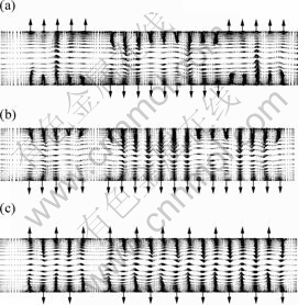
Fig.3 Velocity vector distributions of gas-gas section in furnace
(a) Partial same-side-switching mode;
(b) Same-side-switching mode; (c) Cross-switching mode
3 Results and discussion
3.1 Flow field
Fig.3 shows the velocity vector distributions of gas-gas section in furnace of three different cases. From Fig.3(a), it can be seen that under the condition of partial same-side-switching, because of multi parallel jets�� intervene and interleaving jets between two adjacent zones, the speed vector distribution in each heating zone is abnormal, and large circumfluence exits, which indeed overflows within the side walls. The wider the interval between burners is, the larger the circumfluence will be. Due to the effect of walls, there are some circumfluences near end walls, and with different distances from burner to end wall, the size of circumfluence is different, which is developed adequately within switching period. When combustion is switched, the circumfluence will be confused, but some new circumfluence with reverse direction reforms quickly. The circumfluence of combustion gas can stabilize the further combustion and improve the temperature distribution of furnace.
Fig.3(b) shows velocity vector distribution of gas-gas section in furnace of same-side-switching mode. Because of the same jet direction in each zone, the flow distribution is more stable than that of partial same-side-switching mode. It is not so turbulent, and there is no distinct vortex between heating and soaking zones. The interference of the jet flows is aggravated because of the velocity difference of jets from burners, and some nuances of velocity vector distribution appear. There is a clear vortex between heating and preheating zones, whose style is ���ء� type, different from ��O�� type of reference case.
The velocity vector distribution of gas-gas section in furnace of cross-switching mode is shown in Fig.3(c). From this figure, one can see that reverse jets from adjacent burners cause large vortexes with reverse direction, which almost fill fully two sidewalls and change direction periodically. Though some exhausted outlets surround fluid inlets, it can be seen that even with lower speed, most gases are driven ahead along with mainstreams, and the other gases spread around mainstreams. The gases are stirred and mixed by reflux combusted flue. This evidences that the fresh gases will not be drawn out directly through surrounded exhaust spouts and no short pass problems appear. The same regularity can be found out in the speed field on air-air section in furnace. Because of the existence of so many vortexes, the diffusion area between air and fuel is enlarged, which improves the combustion condition.
3.2 Temperature profile
In heating furnace producing, more attention is paid to the billet heating process and temperature distribution of furnace. The maximum, minimum and average temperatures calculated in nodes of billet after heating are listed in Table 1, where the average temperature is defined by ![]() , where Ti is the
, where Ti is the
calculated temperature of node i and Vi is the control volume of node i. Fig.4 shows the temperature distribution on typical sections for the three cases, and Fig.5 shows each average temperature distribution of flue and billets along the furnace length.
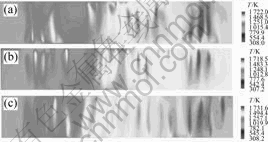
Fig.4 Temperature distribution of y = 850 mm section in furnace
(a) Partial same-side-switching mode;(b) Same-side-switching mode; (c) Cross-switching mode
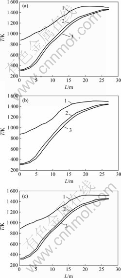
Fig.5 Average temperature distribution along furnace length
1��Furnace temperature of y=1 300 mm section; 2��Billet temperature of upper surfaces; 3��Billet temperature of symmetrical section
(a) Partial same-side-switching mode;(b) Same-side-switching mode; (c) Cross-switching mode
Table 1 Maximum, minimum and average temperatures calculated in nodes of billet after heating
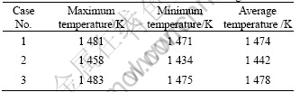
From the simulated results, one can see that in the reference case, the furnace temperature and billet temperature increase gradually from preheating zone to soaking zone. In preheating zone, according to cold billets and lower combustion ability of burners required by the heating technology, the flame temperature and furnace temperature are lower, and the billets are heated slowly with less temperature difference in the thickness direction of billet. In heating zone, the volume of flame gets large and the temperatures of flame and furnace increase, and the heating rate of billets becomes higher with large temperature difference in the thickness direction of billet. While in soaking zone, the furnace temperature increases and the high temperature zone enlarges obviously with even temperature distribution. The terminal heating temperature of billets is more than 1 460 K with little difference. For example, the temperature difference between two nodes is not more than 10 K, which satisfies the heating process.
From Fig.5(a), one can also see that the heating system under producing condition is not very rational. For example, billets in heating zone are not heated deeply enough and the surface average temperature of billets apart from this zone is only about 1 350 K and continued heating is needed in soaking zone. Therefore, the soaking process is shortened within the last 2 m passively. This status is validated by productive practice and needs to be improved in furnace design and operation in the future.
Compared with reference case, the average temperature of furnace of case 2 is lower. As shown in Fig.4(b), according to feebler mixing, at y=850 mm section the flames are relatively thin and short, and the flame zone in the connected zone of heating and soaking zone is even invisible. Additionally, the terminal heating temperature of billets is 30 K lower than that of reference case. This mode is disadvantageous to heat billets quickly and uniformly. As shown in Fig.5(b), the terminal temperature of billets is less than 1 450 K.
The results of cross-switching mode are shown in Fig.4(c) and Fig.5(c). In this case, the flame shape is perfect and one can see 19 distinct flames in the typical section, which are nearly continuous as a whole. The temperature distribution in furnace width direction is much more even. And in furnace length direction, the temperature distribution is reasonable. Within the end 2 m of soaking zone, the average furnace temperature is about 1 520 K, which is stable and a little higher than that of reference case. In this case, when billet moves from heating zone to soaking zone, the average transient temperature of billet surface is about 1 370 K, and that of billet��s central section approaches to 1 350 K, which is about 20 K higher than that of reference case. In this case, both effects of heating and soaking are improved, and the terminal temperature of billets is about 1 470 K with small temperature difference no more than 10 K. Compared with reference case, the cross-switching combustion mode is favorable to heating process.
4 Validation of simulation results
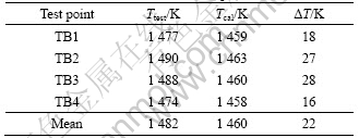
The simulation results of furnace temperature in reference case are validated by on-site testing with six PtRh-Pt thermocouples located in furnace chamber, and terminal temperature of billets is also validated using surface thermometers when the billets slide from furnace onto the roller bed. The results of simulation (Tcal) and testing (Ttest) are listed in Tables 2 and 3. From these tables, it can be seen that the differences of furnace temperature between tested results and calculated results of different points are small. The average difference is 32 K, while the average difference of the surface temperature of billets between tested results and calculated results is 22 K. It can be concluded that the calculated results agree with practical situation well and the simulation model can guide the optimization of producing.
Table 2 Results of furnace temperature
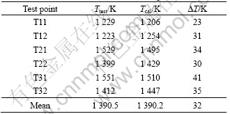
Table 3 Results of surface temperature of billets
5 Conclusions
1) Some thermal information can be obtained in numerical simulation, which can be used to improve the design and operation of HTAC heating furnaces and to optimize HTAC control systems.
2) Perfect profiles of air-flow and temperature can be obtained in HTAC heating furnaces with partial same-side-switching mode, in which the terminal heating temperature of billets is more than 1 460 K and the temperature difference between two nodes is no more than 10 K. But in current, the surface average temperature of billets apart from heating zone is only about 1 350 K and the continued heating is needed in soaking zone. The design and operation of current state are still needed to be optimized for improving the temperature schedule of billet heating.
3) The distribution of velocity and temperature in regenerative reheating furnace with same-side-switching combustion mode cannot satisfy the even and fast heating process for the terminal heating temperature of billets is more than 30 K, which is lower than that of the partial same-side-switching mode. The distribution of flow and temperature can be improved by using cross-switching combustion mode, whose terminal temperature of billets is about 1 470 K with small temperature difference no more than 10 K.
References
[1] WU Zhen-kun, YANG Rui, WANG Jian, et al. Numerical simulation of a 3-D combustion flow field in a single chamber heating furnace with horizontal tubes[J]. Fire Safety Science, 2001, 10(4): 213-217. (in Chinese)
[2] SHU Zheng-chuan, ZHU Tong. Numerical simulation investigation of the combustion system modification scheme for a cell pit furnace[J]. Journal of Engineering for Thermal Energy & Power, 2003, 18(6): 639-639. (in Chinese)
[3] SHEN Bing-zhen, ZHOU Jin, HAN Zhi-qiang, et al. Numerical simulation on temperature field of steel slab in reheating furnace of hot rolling process[J]. Metallurgy Energy, 2002, 21(4): 24-28. (in Chinese)
[4] OU Jian-ping, WU Dao-hong, XIAO Ze-qiang. Numerical simulation on the flow, combustion and heat transfer in regenerative reheating furnace[J]. Industrial Furnace, 2003, 25(1): 44-47. (in Chinese)
[5] WU Cheng-bo, LIANG Xiao-ping, WANG Yu. Numerical simulation of flow and heat transfer in impinging heating furnace[J]. Iron and Steel, 1995, 30(3): 58-62. (in Chinese)
[6] CHEN Ming-ye. The numerical value method of metal heating in continuous rolling mill heating furnace[J]. Journal of Shanghai University of Engineering Science, 1995, 9(2): 37-41. (in Chinese)
[7] ZHANG Wei-jun. Study of Simulation, Optimization and Intelligence on the Control of Thermal Process for Reheating Furnace[D]. Shenyang: Northeastern University, 1998. (in Chinese)
[8] YANG Wei-hong. Application of Computational Fluid Dynamics in Industrial Furnace Research and Development[D]. Changsha: Central South University, 2000. (in Chinese)
[9] YUTAKA S. Regenerative burner heating system[C]// Proceedings of Beijing Symposium on High Temperature Air Combustion. Beijing, The Federation of Engineering Societies of Chinese Association for Science and Technology, 1999: 170-180.
[10] HASEGAWA T, TANAKA R, NIIOKA T. High temperature air combustion contributing to energy saving and pollutant reduction in industrial furnace[C]// Proceedings of Beijing Symposium on High Temperature Air Combustion. Beijing, The Federation of Engineering Societies of Chinese Association for Science and Technology, 1999: 102-114.
[11] WANG Ying-shi, FAN Wei-chen, ZHOU Li-xing, et al. Numerical Computation of Combustion[M]. Beijing: Science Press, 1986. (in Chinese)
[12] TAO Wen-quan. Numerical Heat Transfer[M]. Xi��an: Xi��an Jiaotong University Press, 1988. (in Chinese)
[13] AEA Technology Engineering Software Ltd. CFX4.4 User Documentation[M]. Harwell, 1999.
[14] PATANKAR S V. ZHANG Zheng Tr. Numerical Heat Transfer and Fluid Flow[M]. Beijing: Science Press, 1984. (in Chinese)
[15] MEI Chi. Simulation and Optimization of Nonferrous Metallurgical Furnaces[M]. Beijing: Metallurgical Industry Press, 2001. (in Chinese)
[16] Editorial Committee of References of Industrial Furnace Design for Steel Plant. References of Industrial Furnace Design for Steel Plant (Vol.2)[M]. Beijing: Metallurgical Industry Press, 1979. (in Chinese)
Foundation item: Project(20010533009) supported by the Special Foundation for Doctorate Discipline of China
Received date: 2006-06-25; Accepted date: 2006-09-28
Corresponding author: OU Jian-ping, PhD; Tel: +86-731-8876111; E-mail: oujp@mail.csu.edu.cn
(Edited by YANG Bing)
Abstract: By analyzing the characteristics of combustion and billet heating process, a 3-D transient computer fluid dynamic simulation system based on commercial software CFX4.3 and some self-programmed codes were developed to simulate the thermal process in a continuous heating furnace using high temperature air combustion technology. The effects of different switching modes on injection entrancement of multi burners, combustion and billet heating process in furnace were analyzed numerically, and the computational results were compared with on-site measurement, which verified the practicability of this numerical simulation system. The results indicate that the flow pattern and distribution of temperature in regenerative reheating furnace with partial same-side-switching combustion mode are favorable to satisfy the high quality requirements of reheating, in which the terminal heating temperature of billets is more than 1 460 K and the temperature difference between two nodes is not more than 10 K. But since the surface average temperature of billets apart from heating zone is only about 1 350 K and continued heating is needed in soaking zone, the design and operation of current state are still needed to be optimized to improve the temperature schedule of billet heating. The distribution of velocity and temperature in regenerative reheating furnace with same-side-switching combustion mode cannot satisfy the even and fast heating process. The terminal heating temperature of billets is lower than that of the former case by 30 K. The distribution of flow and temperature can be improved by using cross-switching combustion mode, whose terminal temperature of billets is about 1 470 K with small temperature difference within 10 K.
