
J. Cent. South Univ. (2016) 23: 721-728
DOI: 10.1007/s11771-016-3117-x

Seismic response analysis of GRPS embankment under oblique incident P wave
GAO Xin-jun(۬�¾�), QIAN Hui(Ǯ��), GUO Yuan-cheng(��Ժ��), WANG Fei(����)
School of Civil Engineering, Zhengzhou University, Zhengzhou 450001, China
 Central South University Press and Springer-Verlag Berlin Heidelberg 2016
Abstract:
In order to investigate the seismic performance of geosynthetic reinforced and pile supported (GRPS) embankment under seismic loads, an input method for three-dimensional oblique incidence of P wave was proposed. This method is based on the explicit finite element method while considering the viscous-spring artificial boundary (VSAB) condition. Using the proposed method, a numerical study was conducted, and the influence of oblique incidence on the seismic response of GRPS embankment under the oblique incident P waves was analyzed. The results indicate that in comparison with vertical incidence, the oblique incidence can significantly increase the displacement, velocity and acceleration of key locations in the GRPS embankment. The existence of geosynthetics can alleviate the impact of seismic load on the response of the embankment to a certain degree. Moreover, the number of reinforcement layers and modulus of geogrid also greatly influence the seismic performance of GRPS embankment.
Key words:
1 Introduction
Geosynthetic reinforced and pile supported (GRPS) embankments are known for their prominent advantages in convenient construction, short construction period, small lateral deformation and post-construction settlement, etc. GRPS embankment has lately been widely used in highways and railways that are constructed over soft soil area and other fields. Recently, scholars around the world have conducted in-depth research in GRPS embankments [1-4], and a number of design specifications for this structure have been issued, such as Japanese Handbook (2001), Nordic Guidelines (2004) and British Standard BS8006 (2010). However, the above studies and standards focused mostly on static analysis of GRPS embankment, such as soil arching effect of embankment, geotextiles and deformation, as well as mechanical properties of pile foundations [5-9]. At present, relatively few literatures have reported efforts regarding the research of seismic performance of GRPS embankments [10-12]. At the same time, the intensity and stability analysis of GRPS embankments under earthquake excitation were carried out through static methods. In these methods, the seismic load was regarded as an inertial force imposed on the structure. These methods can be acceptable for structures with small lateral stiffness and short extensions, and are placed in a uniform field. For long and narrow embankment structures, however, the combination of local geological conditions, seismic wave and other factors can cause significant spatially non-uniform ground motions. A number of seismic damage investigations of embankments have indicated that non- uniform factors will be harmful to the seismic performance of embankments [13-15]. Therefore, as more and more GRPS embankments are built and applied in regions that experience high intensity earthquake, the seismic performance of GRPS embankments under non-uniform excitation is of vital significance.
In this work, the seismic response and mechanics of GRPS embankment under the loading from oblique incident P wave were analyzed systematically. Firstly, based on the explicit finite element method coupled with the viscous-spring artificial boundary (VSAB) condition, the formula for equivalent nodal force in three-dimensional coordinates for the oblique incident P wave was derived. And then, a three-dimensional numerical model and a high efficiency calculation method for the whole GRPS embankment system under non-uniform ground motion were established.
2 Input method of oblique incident P wave
2.1 Viscous-spring artificial boundary
Artificial boundary can approximately simulate the radiation of the infinite foundation, which is usually set as the finite element model boundary to analyze seismic response of embankment structure while considering the dynamic interaction of foundation and embankment structure. Among them, the viscous-spring artificial boundary is widely used for its advantages of frequency stability, high precision and applicability [16-18]. According to the theory of the VSBA, the spring stiffness and damping coefficient of node l in the VSAB can be expressed as
 (1)
(1)
where Kli, Klj, Cli and Clj represent normal spring stiffness, tangential spring stiffness, normal damping coefficient and tangential damping coefficient of node l in the VSBA, respectively. G represents shear modulus of soil. Al represents the influence area of boundary node l. �� represents mass density of soil. cP represents wave velocity of P wave and cS represents wave velocity of S wave. ai and aj represent the normal and tangential spring modification coefficients, respectively. R represents the distance from the wave source to the node l in the VSAB.
2.2 Input method of oblique incident P wave
The seismic response of embankment structure is analyzed when using the VSAB condition, and two conditions need to be met simultaneously. Incident wave propagates through the boundary without reflecting and scattered wave is absorbed in the boundary. Then, the total wave field in the artificial boundary could be decomposed into infield and outfield. The total wave field equation of motion in l direction of node l in artificial boundary can be expressed as

 (2)
(2)
 (3)
(3)
where ml represents the lumped mass of node l. Klikj and Clikj represent the stiffness and damping coefficients of node k in j direction responding to i direction of node l, respectively. ukj and  represent the displacement and speed of node k in j direction. uki and represent the displacement and speed of node l in i direction. ��li represents the stress of node l in i direction in free field caused by incident and scattered wave. fli represents the imposed equivalent force of node l in i direction, while ��ij=1 when i=j and ��ij=0 when i��j. For the 3D situation, n=3, the subscript i=1, j=2, k=3 corresponds to x, y, and z in the rectangular coordinates, respectively.
Herein, the problem of wave motion is converted into the problem of equivalent force input in the VSBA. Thus, the wave input issue is converted into solving equivalent nodal force fli applied to artificial boundary. How to determine the stress ��li, uli and  through the known incident plane wave is the key point.
2.3 Equivalent force calculation
It is assumed that incident P wave propagates obliquely from lower left corner of 3D model at an angle �� in xoy place, as shown in Fig. 1. According to the wave theory, the constitutive relation of medium and the transformation formula of stress component coordinate, the stress field diagram of incident P wave, reflected P wave and reflected SV wave in free field can be obtained, as shown in Fig. 2. The stress values are shown in Eq. (4) to Eq. (6), respectively:
 (4)
(4)
 (5)
(5)
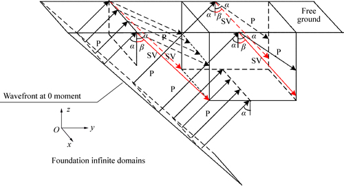
Fig. 1 Three-dimensional diagram of oblique incidence of plane P wave (Before, behind left and right side of three-dimensional model are all visco-spring artificial boundary surfaces)
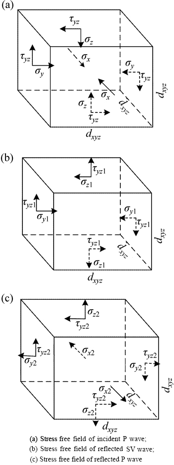
Fig. 2 Stress fields of incident and reflected waves:
 (6)
(6)
where A1 and A2 represent the reflection coefficients of P wave and SV wave, respectively. �� is the reflection angle of SV wave.
By the geometric relationships between the incident wave and the reflected wave, the displacement vector of node l can be obtained by
 (7)
(7)
where ��ti, ��tj and ��tk represent the delay times of wave propagation relative to initial calculation time. ��t1, ��t2 and ��t3 represent the delay times of incident P wave, reflected P wave and SV wave from left boundary, respectively. ��t4, ��t5 and ��t6 represent the delay times of incident P wave, reflected P wave and SV wave from right boundary, respectively. ��t7, ��t8 and ��t9 represent the delay times of incident P wave, reflected P wave and SV wave from bottom boundary, and ��t10, ��t11 and ��t12 represent the delay times of incident P wave, reflected P wave and SV wave from before and back boundary, respectively. These delay times can be obtained by geometric relations between the incident wave and reflected wave. The corresponding wave velocity can be obtained by the derivative of Eq. (7).
According to the stress state and transformation formula for stress state of plane wave, the stresses of the node l on the left, right, bottom, front and back boundary can be obtained:
 (8)
(8)
 (9)
(9)
 (10)
(10)
 (11)
(11)
 (12)
(12)
By substituting Eqs. (8)-(12) into Eq. (3), the equivalent force of the corresponding nodal in the boundary under oblique incident P wave at an angle of �� can be obtained, and then the input of seismic wave can be realized.
2.4 Wave input method verification
Based on the wave theory, the displacement of half space free surface is twice of the vertical incident wave. When oblique incident P wave propagates at ��=0.001, it can be regarded as approximately vertical incidence because the incidence angle is small enough. It is used to verify whether the results meet the above wave theory for this case. The geometric dimension of the model is 100��100��100, and the mesh size is 5��5��5. Elastic modulus E=1.25��109, Poisson ratio ��=0.25 and density ��=1800. It is assumed that the oblique incident P wave propagates from the left lower corner of the 3D model at ��=0.001 in the xoy plane. All values are dimensionless in this example.
Incident wave displacement time history curve is u(t)=sin4��t-0.5sin8��t, as shown in Fig. 3. And the displacement response of upper free surface is shown in Fig. 4. From Fig. 4, the peak value of the displacement in the free surface is twice of incident wave, which indicates that the input method of 3D oblique incidence of P wave has high accuracy and stability.
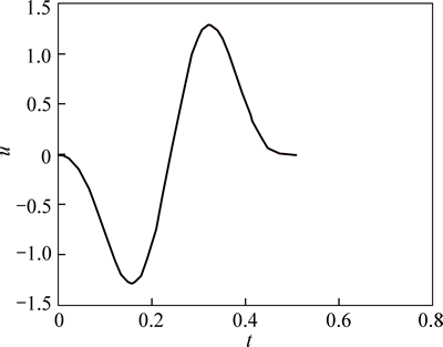
Fig. 3 Displacement time history curve of incident P wave
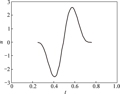
Fig. 4 Displacement time history curve of reflected P wave in free surface
3 Numerical modeling
3.1 3D numerical model
In this work, a certain region of GRPS embankment as a part of Lianhuo highway as the research object was taken into account. The overall calculation model of embankment is 10 m long, 65 m (20 m+4.5 m+16+4.5 m+20 m) wide and 20 m high. The height of filled soil part in the embankment is 4 m with four geogrid layers. The physical parameters of foundation soil, geogrid and pile foundation are given in Table 1 and Table 2. C3D8R unit was chosen to generate mesh for the soil model. Mohr-Coulomb criterion was selected as the strength criterion. The upper boundary of numerical model was free and the rest boundaries were the VSAB. The finite element model contains 100946 nodes and 57953 unit cells. The numerical model of foundation- embankment is shown in Fig. 5.
Table 1 Parameters of soil
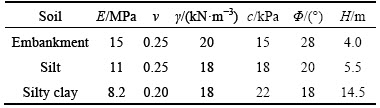
Table 2 Parameters of concrete materials
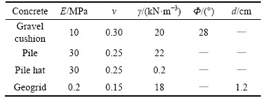
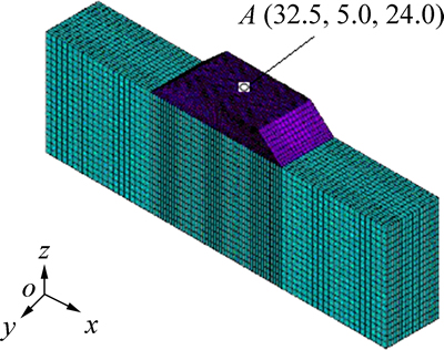
Fig. 5 Finite element model of GRPS under seismic load
3.2 Earthquake wave selection
Input seismic wave record was the record of Kobe wave, in 1955, and last 40 s. Seismic wave velocity and displacement time history used in the calculation were obtained through the filtering and integration of acceleration time history curve, as shown in Fig. 6. The seismic waves were programmed to input once in the ABAQUS model boundary.
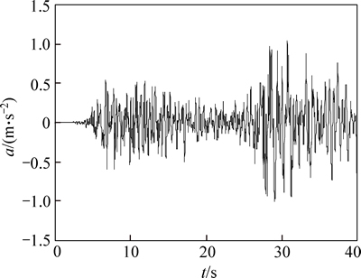
Fig. 6 Time history curve of seismic wave acceleration
When oblique incident P wave was input at the different angles, such as 0��, 30�� and 60��, the seismic response of different geogrid layers and various geogrid modulus of GRPS embankment were investigated, and the nodes (32.5, 5.0 and 24.0) were selected as the reference point A, as shown in Fig. 5.
4 Results and analysis
4.1 Influence of incident angles of P wave
It is assumed that P wave propagates obliquely from the bottom of the model along z direction at 0��, 30�� and 60��, respectively. Figure 7 shows the time history curve of displacement, acceleration in x direction of Point A and tensile stress of the first geogrid layer. As seen from Fig. 7, the peak displacement and acceleration as well as tensile stress of geogrid increase constantly with the increasing of incident wave angle. Especially, when the angle increases from 0�� to 30��, the displacement, acceleration and tensile stress increase from 0.0523 m, 0.112 m/s2 and 14.892 MPa to 0.258 m, 0.791 m/s2 and 71.545 MPa, respectively. The peak displacement and acceleration in x direction of Point A indicate the damage degrees of GRPS embankment in certain extend during the earthquake.
Therefore, the incident angle of seismic wave has great effect on the seismic response of GRPS embankment during earthquake. Thus, the traditional input method which only considers vertical incidence of seismic wave was imperfect, and oblique incidence of wave should be paid more attention to during design phase.
4.2 Influence of reinforced geogrid cases
Assuming P wave incident propagates at 60�� and the rest of the parameters are maintained at the initial values. The tensile stress time history curves of each layer geogrid laid in the center line of the GRPS embankment are shown in Fig. 8.
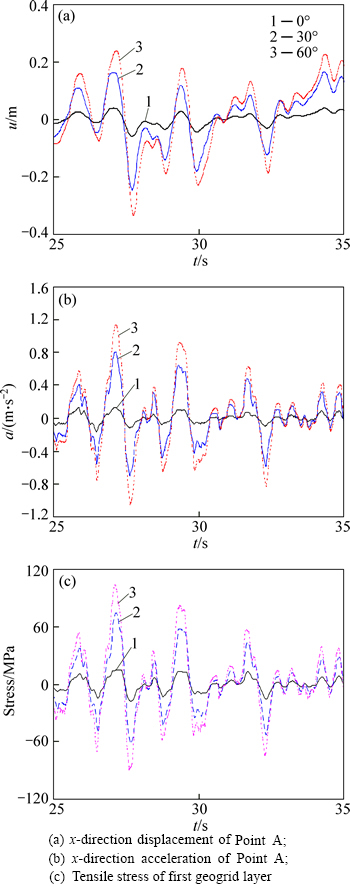
Fig. 7 Time-history curves of seismic response at Point A under different wave incident angles:
Figure 8 shows that the peak tensile stress decreases constantly from the first layer (the bottom layer) to the fourth layer (the top layer). And the peak tensile stresses of the first and fourth layers are 143.716 MPa and 88.365 MPa, respectively, indicating that flexible geogrids laid in the bottom of GRPS embankment can alleviate seismic damages effectively, which is also in accordance with characteristics of GRPS embankment.
To further investigate the influence of the geogrid, the seismic response of GRPS embankment with and without a layer of geogrid was analyzed. Thedisplacement time history curves in x direction of Point A and shear stress time history curves are shown in Figs. 9(a) and (b), respectively.
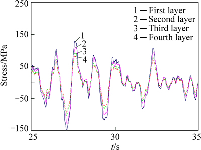
Fig. 8 Tensile stress time-history curve of geogrid at different layers
Figure 9(a) shows that peak displacement in x direction at Point A is 0.528 m without geogrid while 0.325 m with a layer of geogrid. The peak displacement decreases by 0.067 m, with a reduction rate of 38.4%. Figure 9(b) shows that the peak shear stress is 53.619 MPa without geogrid while 31.980 MPa with a layer of geogrid. The reduction rate is 40.35%. The results indicate that the geogrid can observably mitigate the seismic response of embankment.
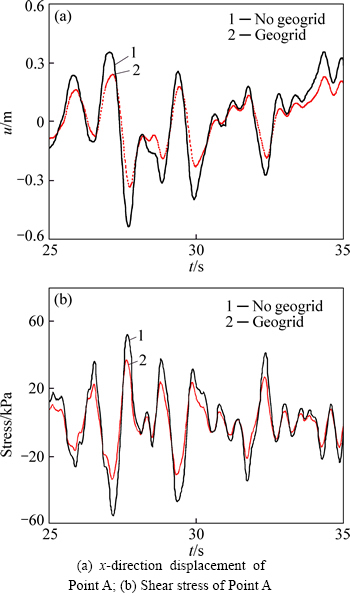
Fig. 9 Time history curves of seismic response with and without considering geogrid:
Figure 10 shows the peak displacement and shear stress of Point A of the GRPS embankment with different layer geogrid numbers under oblique incident P wave at 60��.
It can be seen from Fig. 10 that the peak displacement and shear stress of Point A decrease with the increasing of the layer numbers. Especially, from one-layer case to two-layer case, the peak displacement and shear stress decrease by 0.045 m and 5.7 MPa, respectively. However, three-layer case and four-layer case are almost similar. The results indicate that the geogrid layer numbers significantly affect the seismic response of GRPS embankment. With the increasing of geogrid layer number, the seismic response of GRPS embankment decreases, while there is a limited value.
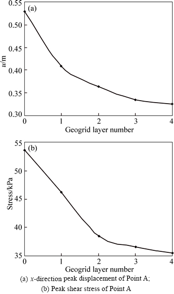
Fig. 10 x-direction peak displacement and peak shear stress of Point A under different geogrid layer numbers:
Figure 11 shows the x-direction and z-direction peak displacements at Point A when geogrid modulus is 0.2 GPa, 0.4 GPa, 0.8 GPa and 1.4 GPa, respectively.
From Fig. 11, it can be known that x-direction and z-direction peak displacement decrease with the increasing of the geogrid modulus. The x-direction peak displacement when the geogrid modulus is 1.4 GPa can be reduced by 15.2% compared with that when thegeogrid modulus is 0.2 GPa. Similarly, the z-direction peak displacement can be reduced by 29.5%. So, the increasing of the geogrid modulus has a relatively large influence on z-direction peak displacement compared with x-direction displacement in earthquake.

Fig. 11 x-direction and z-direction peak displacements of Point A under different elastic modulus of geogrid:
5 Conclusions
1) The angle of incident wave has great influence on the seismic response of GRPS embankment. With the increasing of the incident angle of P wave, the seismic response of GRPS embankment gradually increases, especially ranging from 0�� to 30��. The traditional wave input method is unsafe.
2) When incident P wave is input at a certain angle, the tensile stress of geogrid decreases constantly from the bottom layer to the top layer. This indicates that the flexible geogrid can effectively alleviate seismic response of GRPS embankment. The existence of the geogrid makes GRPS embankment safer during earthquake.
3) The geogrid layer number also has significant effect on the seismic response of GRPS embankment. The seismic response of GRPS embankment decreases with the increasing of the geogrid layer number. However, there is an optimum geogrid layer number. Seismic response of GRPS embankment is no longer sensitive when the geogrid layer number exceeds one optimum value.
4) Increasing of the modulus of geogrid can reduce the horizontal and vertical peak displacement of GRPS embankment, especially for the vertical peak displacement.
References
[1] RUSSELL D, PIERPOINT N. An assessment of design methods for piled embankments [J]. Ground Engineering, 1997, 24(2): 39-44.
[2] ARIYARATHEN P, LIYANANPATHIRANA D S, LEO C. Comparison of different two dimensional idealizations for a geosynthetic-reinforced pile-supported embankment [J]. International Journal of Geomechanics, 2013, 13(6): 754-768.
[3] LIU Hong-kai, XIA Tang-dai. Pile-soil stress analysis of geogrid- reinforced pile-supported embankment with piles arranged in triangle [J]. Journal of Central South University (Science and Technology), 2014, 45(11): 3957-3963. (in Chinese)
[4] ZHANG Jun, ZHENG Jun-jie, MA Qiang. Performance of fixed geosynthetic technique of GRPS embankment [J]. Journal of Central South University, 2013, 20(8): 2245-2254.
[5] BRIANCON L, SIMON B. Performance of pile-supported embankment over soft soil: Full-scale experiment [J]. Journal of Geotechnical and Geoenvironmental Engineering, 2012, 138(4): 551-561.
[6] SHUKLA S K, KUMAR R. Overall slope stability of prestressed geosynthetic reinforced embankments on soft ground [J]. Geosynthetics International, 2008, 15(2): 165-171.
[7] WACHMAN G S, BIOLZIL, LABUZ J F. Structural behavior of a pile-supported embankment [J]. Journal of Geotechnical and Geoenvironmental Engineering, 2010, 136(1): 26-34.
[8] EllS E A, ASLAM R. Arching in piled embankments: Comparison of centrifuge tests and predictive methods-Part 1 of 2 [J]. Ground Engineering, 2009, 42: 34-38.
[9] LOW B K, TANG S K, CHOA V. Arching in piled embankments [J]. Journal of Geotechnical Engineering, ASCE, 1993, 120(11): 1917-1938.
[10] KOSEKI, J. Use of geosynthetic to improve seismic performance of earth structures [J]. Geotextiles and Geomembranes, 2012, 34: 51-68.
[11] TAHA A, HESHAM E, NAGGAR M, TURAN A. Experimental study on the seismic behaviour of geosynthetic-reinforced pile- foundation system [J]. Geosynthetics International, 2015, 22(2): 183-195.
[12] QUANG T S, GHAZI H, PATRICK D B. Seismic stability analysis of piled embankments: A multiphase approach [J]. International Journal for Numerical and Analytical Methods in Geomechanics, 2010, 34: 91-110.
[13] WANG Jian, YAO Ling-kan, CHEN Qiang. Research on failure mode of road embankment Wenchuan great earthquake and deformation control of geogrid reinforcement [J]. Chinese Journal of Rock Mechanics and Engineering, 2010, 29(S1): 3387-3394. (in Chinese)
[14] KUWANO J, MIYATA Y, KOSEKI J. Performance of reinforced soil walls during the 2011 Tohoku earthquake [J]. Geosynthetic International, 2014, 21(3): 1-18.
[15] KOSEKI J, SHIBUYA S. Mitigation of disasters by earthquakes, tsunamis, and rains by means of geosynthetic-reinforced soil retaining walls and embankments [J]. Transportation Infrastructure Geotechnology, 2014, 1(3/4): 231-261.
[16] LIU Jing-bo, LU Yan-dong. A direct method for analysis of dynamic soil-structure interaction [J]. China Civil Engineering Journal, 1998, 31(3): 55-64. (in Chinese)
[17] GAO Xin-jun. Seismic response analysis of longspan bridge considering earthquake and vertical trainloads [D]. Beijing: Beijing Jiaotong University, 2011. (in Chinese)
[18] XU Qiang, CHEN Jian-yun, LI Jing. Influence of seismic input on response of Baihetan arch dam [J]. Journal of Central South University, 2014, 21(6): 2437-2443.
(Edited by YANG Bing)
Foundation item: Projects(41202220, 41472278, 51478438) supported by the National Natural Science Foundation of China; Projects(20120022120003, 20134101120009) supported by the Research Fund for the Doctoral Program of Higher Education, China; Project(2652012065) supported by the Fundamental Research Funds for the Central Universities, China; Project(14A560014) supported by the Key Project of Education Department in Henan Province, China
Received date: 2015-04-10; Accepted date: 2015-08-25
Corresponding author: GAO Xin-jun, PhD; Tel: +86-371-67781680; E-mail: gxjun@zzu.edu.cn
Abstract: In order to investigate the seismic performance of geosynthetic reinforced and pile supported (GRPS) embankment under seismic loads, an input method for three-dimensional oblique incidence of P wave was proposed. This method is based on the explicit finite element method while considering the viscous-spring artificial boundary (VSAB) condition. Using the proposed method, a numerical study was conducted, and the influence of oblique incidence on the seismic response of GRPS embankment under the oblique incident P waves was analyzed. The results indicate that in comparison with vertical incidence, the oblique incidence can significantly increase the displacement, velocity and acceleration of key locations in the GRPS embankment. The existence of geosynthetics can alleviate the impact of seismic load on the response of the embankment to a certain degree. Moreover, the number of reinforcement layers and modulus of geogrid also greatly influence the seismic performance of GRPS embankment.
