

J. Cent. South Univ. (2020) 27: 937-950
DOI: https://doi.org/10.1007/s11771-020-4342-x

Effect of bolt inclination angle on shear behavior of bolted joints under CNL and CNS conditions
CUI Guo-jian(����)1, 3, ZHANG Chuan-qing(�Ŵ���)1, 3, CHEN Jian-lin(�½���)2,
YANG Fan-jie(���)1, 3, ZHOU Hui(�ܻ�)1, 3, LU Jing-jing(¬����)1, 3
1. State Key Laboratory of Geomechanics and Geotechnical Engineering, Institute of Rock and Soil Mechanics, Chinese Academy of Sciences, Wuhan 430071, China;
2. Power China Huadong Engineering Corporation Limited, Hangzhou 310014, China;
3. School of Engineering Science, University of Chinese Academy of Sciences, Beijing 100049, China
 Central South University Press and Springer-Verlag GmbH Germany, part of Springer Nature 2020
Abstract:
Rock bolts are widely used in rock engineering projects to improve the shear capacity of the jointed rock mass. The bolt inclination angle with respect to the shear plane has a remarkable influence on the bolting performance. In this study, a new artificial molding method based on 3D scanning and printing technology was first proposed to prepare bolted joints with an inclined bolt. Then, the effects of the bolt inclination angle and boundary conditions on the shear behavior and failure characteristic of bolted joints were addressed by conducting direct shear tests under both CNL and CNS conditions. Results indicated that rock bolt could significantly improve the shear behavior of rock joints, especially in the post-yield deformation region. With the increase of bolt inclination angle, both the maximum shear stress and the maximum friction coefficient increased first and then decreased, while the maximum normal displacement decreased monotonously. Compared with CNL conditions, the maximum shear stress was larger, whereas the maximum normal displacement and friction coefficient were smaller under the CNS conditions. Furthermore, more asperity damage was observed under the CNS conditions due to the increased normal stress on the shear plane.
Key words:
Cite this article as:
CUI Guo-jian, ZHANG Chuan-qing, CHEN Jian-lin, YANG Fan-jie, ZHOU Hui, LU Jing-jing. Effect of bolt inclination angle on shear behavior of bolted joints under CNL and CNS conditions [J]. Journal of Central South University, 2020, 27(3): 937-950.
DOI:https://dx.doi.org/https://doi.org/10.1007/s11771-020-4342-x1 Introduction
Rock bolts are wildly used in various rock engineering projects to reinforce unstable rock mass. For rock bolts installed in the uniformly deformed rock mass, the bolt is mainly subjected to tension load. However, for rock bolts installed in the jointed rock mass, the bolt may be subjected to both tension and shear loads due to open and slide of rock joint [1-4]. To date, most researchers mainly focused on tension performance of rock bolt and achieved outstanding achievements on rock bolting mechanism [5-14]. Compared with the tension behavior of rock bolt, the shear behavior of rock bolt was less studied, although it��s essential for support design scheme and engineering stability in jointed rock masses, suggesting that bolting mechanism in the jointed rock mass is still not fully revealed.
Bolted rock joints consist of the following four components: the upper and lower halves of rock blocks, rock joint between upper and lower blocks, grouting material, and rock bolt. All four components codetermine the shear behavior of bolted joint. Therefore, the shear behavior of bolted joints is related to joint morphology, the mechanical property of rock mass, grouting and rock bolt, bolt and borehole diameter, bolt inclination angle with respect to the shear direction, bolt pretension and so on. Researchers have carried out a large number of shear tests including single shear tests and double shear tests to study the influence of the above factors [15-23]. The results showed that shear strength increases with the increase of joint roughness, bolt diameter and rock strength, and varies with the bolt type and bolt profiles. Rock bolts installed on site were not always perpendicular to the joint shear direction due to the limitation of construction conditions and change of joint orientation, so the evaluation of the shear behavior of bolted joint with different bolt inclinations is critical in the application of rock bolt and optimization of support design scheme, which are unfortunately ignored in the most of the previous studies. Because it��s challenging to prepare matched rough joint specimens with inclined bolt in the laboratory, the joint surfaces usually were simplified as regular or planar joint profile, and the bolt was directly encapsulated into joint specimens without grouting material when the bolt is inclined [16, 22]. They found that the peak shear strength occurs at an initial inclination to the joint in the range of 30��C60��. Further, CHEN [2] developed a new method that can apply the combined pull and shear loads to the rock bolt simultaneously.
The boundary conditions of the direct shear test also influence shear behavior. Two different normal boundary conditions, i.e., constant normal load (CNL) and constant normal stiffness (CNS) boundary conditions, are broadly applied in the shear tests of rock joints [24-29]. A comparison of shear behavior under different boundary conditions indicated that shear strength was underestimated and dilation was overestimated under the CNL conditions, especially at low initial normal stress level. Besides, more asperity damage was observed under the CNS conditions due to the increased normal stress on the shear plane.
For bolted rock joints, most studies were conducted under the CNL conditions, and the test results indicated that the shear strength increased with the increase of applied normal stress [17]. However, CNL boundary condition is only suited to simulate the shear behavior of bolted joints where the dilation of surrounding rock mass is free, such as bolted slope, but not suited to simulate the situation where dilation is resisted by the surrounding rock mass, which is frequently encountered on-site and should be simplified as CNS conditions. INDRARATNA et al [30] carried out single shear tests on saw-tooth shaped artificial joints grouted with 3 mm bolts under the CNS conditions and proposed an analytical model to predict the shear resistance of bolted joints using the Fourier Series.
From engineering perspectives, the improvement of shear behavior of bolted rock joints can be achieved mainly by the optimization of the mechanical property of grouting material and surrounding rock mass, dimension of the borehole and rock bolt, bolt type, bolt profiles, and bolt inclination angle because of the limitation of geological engineering and construction conditions. As discussed in the previous two paragraphs, these influence factors have been studied systematically under the CNL conditions in addition to the bolt inclination angle because it��s difficult to prepare the bolted rough joint specimens with inclined rock bolt. However, the shear behavior of bolted joints under the CNS condition is barely studied so far. Hence, in this paper, we first proposed a new specimen preparation method for bolted rough joints with any bolt inclination angle based on 3D scanning and 3D printing technology. By adopting this method, bolted rough joint specimens with bolt inclination angles of 30��, 45��, 60��, 75�� and 90�� were prepared, respectively. Then, the direct shear tests of bolted joint specimens with different bolt inclinations were carried out under both CNL and CNS conditions. Finally, the effect of bolt inclination angle and boundary conditions on the mechanical behaviors and deformation of bolted joints were determined, and the joint surface failure characteristic was analyzed.
2 Specimen preparation and experimental set-up
2.1 Bolted joint specimen preparation method
To study the influence of bolt inclination angle on the shear behavior of bolted joints, the bolt inclination angle should be the only variable in the shear test. Hence, the joint surface morphology of bolted specimens should be as similar as possible to reduce its influence and obtain comparable test results. However, it��s almost impossible to obtain natural rock joints with similar surface morphology due to the inherent uncertainties of rock joints. Additionally, the inclined bolt is difficult to be installed in the joint specimen. Inclined bolt installation procedure was simplified by the following two ways in the previous study: 1) rough joint surface was simplified as two-dimensional (2D) regular surface or planar; 2) bolt was directly encapsulated into joint specimens when casting. The simplified installation methods ignore the effect of either three-dimensional (3D) morphology or grout material on the shear behavior of bolted joints. In order to overcome the abovementioned difficulties, a new artificial molding method based on 3D scanning and printing technology was proposed to prepare bolted joint specimens in this context. The bolted joint specimens with any surface morphology, bolt numbers, and bolt inclination angle can be prepared using this method.
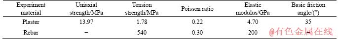
The gypsum slurry with water-to-cement (W/C) ratio of 1:3 was selected as model material, the HRB400 rebar with diameter of 6 mm and length of 100 mm was used as rock bolt, and the cement paste with W/C ratio of 3:5 was selected as grouting material in this study.
The main steps of this new method are as follows:
1) First, a 3D photo scanner (type HL-3DS+) with a measurement precision of ��0.012 mm was used to replicate and measure the prototypical joint surface morphology, which was obtained by splitting intact rock (Figure 1(a)). The scanner is composed of a grating launcher, two charge- coupled device (CCD) cameras, and a pan-tilt. The reconstructed virtual joint surface is shown in Figure 1(b).
2) Next, the virtual joint surface was extruded two-way along the normal direction of the joint surface to generate a 3D printed joint model of unbolted joint so that the top and bottom joint surfaces are well-matched. Further, to reserve a bolt hole for installing rock bolt with different inclination angle for bolted joint specimens, two identical inclined cylinder holes with a diameter of 12.2 mm and an inclined angle of �� with respect to shear direction was generated through the center of the top and bottom surfaces of the unbolted joint model, respectively. The 3D printed model of bolted joints is shown in Figure 1(c).
3) After the 3D printed joint model was prepared, the printed molds were manufactured using a 3D printer.
4) Before casting, the printed mold was installed inside steel mold, and then two greased solid steel rods with 12 mm diameter were placed through the two reserved holes for preparing bolt installation hole (Figure 1(d)).
5) Mixing model material evenly (Figure 1(e)), then the mixture was poured into the steel molds and vibrated for 30 s to reduce air bubbles (Figure 1(f)).
6) The joint specimens were removed from the steel mold after about 0.5 h and cured in air conditions (Figure 1(g)).
7) For bolted joint specimens, two solid steel rods were removed from the specimen, and the bolt was grouted into the reserved hole after curing for a week (Figures 1(h)-(i)).
Finally, a large number of unbolted and bolted joint specimens were prepared for the direct shear tests. The specimens have dimensions of 100 mm�� 100 mm��100 mm. All specimens were cured for at least 28 d before testing.
The basic mechanics properties of model material were determined by performing uniaxial compression test on cylinder specimens (0.05 m in diameter and 0.1 m in height), indirect tension test on cylinder specimens (0.05 m in diameter and 0.025 m in height) and tilt test on smooth joint surfaces at the State Key Laboratory of Geomechanics and Geotechnical Engineering of Institute of Rock and Soil Mechanics, China. The tested specimens were prepared from the same casting batch as joint specimens. Every test was repeated three times to reduce the dispersion of test results. The average of the test results was used, as summarized in Table 1.
2.2 Quantification of joint surface morphology
Joint roughness coefficient (JRC), which was first proposed by BARTON [31], is a widely used parameter to quantify joint surface morphology. The quantification method recommended by Barton and (International Society for Rock Mechanics and Rock Engineering) ISRM involves a visual comparison of 2D joint surface profile lines against 10 standard joint profile lines. Obviously, this method is subjective and only applies to the 2D joint surface. Further, many new methods were developed to determine the JRC of 2D and 3D joint surfaces based on statistical roughness parameters and fractal dimension [31-34]. The modified root mean square method developed by TATONE et al [33] was used in the present study.
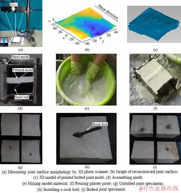
Figure 1 Preparation process of unbolted and bolted joint specimens:
Table 1 Basic mechanical parameters of model material and rock bolt
2D profile lines were extracted from the 3D joint model along the shear direction with line spacing of 5 mm for calculating JRC, the value of Z2 of each profile line was calculated using the following equation:
 (1)
(1)
where Z2 is the root mean square of the first derivative of the profile; L is the projected length of a joint profile in the shear direction; xi and zi are the coordinate value of sampling point; and N is the number of the sampling point.
After that, JRC of the j-th profile can be estimated from Z2 as:
 (2)
(2)
where JRCj and Z2j are the value of joint rough coefficient and Z2 of the j-th profile.
The value of JRC of 3D rough joint is considered as the average of the joint rough coefficient of all two-dimensional profiles and can be calculated by:
 (3)
(3)
where m is the number of two-dimensional profile lines.
The calculated JRC of tested nature joint was 7.1 based on 19 measured profile lines.
2.3 Test apparatus and test design
A servo-controlled shear test apparatus, namely RJST-616, was used to conduct direct shear tests of unbolted and bolted joint specimens with different bolt inclinations under both CNL and CNS boundary conditions (Figure 2) [14]. The apparatus is composed of a loading unit, a hydraulic servo control system, a data acquisition system, and a control software module. Both CNL and CNS normal boundary conditions can be achieved by feedback hydraulic servo control system. The normal and shear force can be programmed to apply by servo-controlled vertical and horizontal loading pistons with the maximum loading capacity of 200 and 300 kN, respectively. Load cells and linear variable differential transformers (LVDTs) are used to measure load and displacement during shearing with a data acquisition frequency of 10 Hz. The matched joint specimen was put into two split shear boxes, and the size of each shear box was 100 mm�� 100 mm��47.5 mm. The lower shear box was placed on the top of a linear slider for reducing the friction and can only move along the horizontal direction, whereas the upper shear box was fixed in the horizontal direction and can only move along the vertical direction.
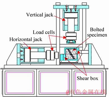
Figure 2 Schematic diagram of CNL and CNS rock joint direct shear test apparatus (RJST-616)
In this study, the effects of bolt inclination and normal boundary conditions on the shear behavior of unbolted and bolted clean joint specimens were investigated. The prescribed initial normal stress was set to be 0.5 MPa, the normal stiffness was set to be 0 GPa/m (CNL) and 2 GPa/m (CNS), and the bolt inclination angle �� was set to be 30��, 45��, 60��, 75�� and 90�� for bolted joint specimens, respectively. The normal stiffness was set to be 2 GPa/m according to the previous study on unbolted rock joints under the CNS conditions [24, 25].
When conducting the direct shear test, the prescribed initial normal force was first applied at a loading rate of 0.1 kN/s, then CNL or CNS conditions were maintained until the end of the shear test. Meanwhile, the shear force was applied at a displacement rate of 0.005 mm/s. All load and displacement data will be recorded by a data acquisition system and displayed in real-time by a computer.
3 Results
3.1 Shear test results of unbolted joints
The shear test results of unbolted joints under both CNL and CNS conditions are shown in Figure 3. As observed in Figure 3(a), the normal stress �� kept constant under CNL conditions during the shearing process, whereas it almost linearly varied with normal displacement v under CNS conditions because coefficient of determination R2 of the linear fitting curve is 1.00. The fitting result of normal stress-normal displacement curve under CNS condition indicated that the measured value of normal stiffness is in accordance with the input normal stiffness, revealing that both CNS and CNL shear tests can be conducted with good accuracy using RJST-616. Therefore, the normal stress versus normal displacement curves of the rest of the shear tests under both CNL and CNS conditions aren��t depicted for convenience.
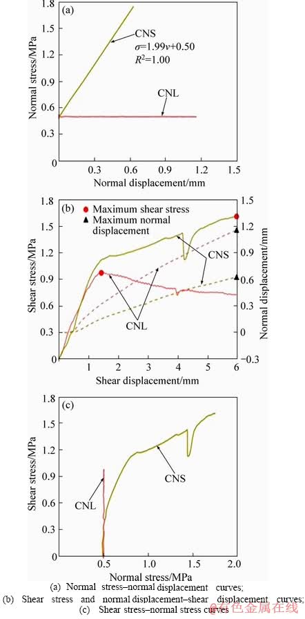
Figure 3 Shear behavior of unbolted joints under both CNL and CNS conditions:
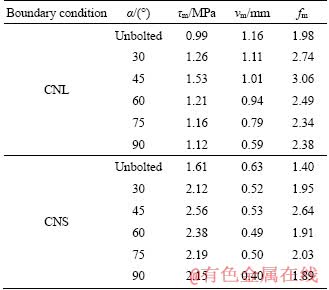
In Figure 3(b), the solid lines represent the shear stress-shear displacement curves, which are plotted on the left axis; the dotted lines represent the normal displacement-shear displacement curves which are plotted on the right axis, and red circle and black triangle represent the maximum of shear stress and normal displacement, respectively. Strain-softening behavior occurred in the CNL test, while strain-hardening behavior was observed in the CNS test, suggesting that post-yield mechanical behavior was improved significantly when normal stiffness was applied. The abrupt drop of shear stress under the CNS condition in Figure 3(b) may result from the local damage of asperities. For strain-hardening curves, no shear stress peak was attained, and the maximum shear stress obtained from shear stress-shear displacement curves were used in this study. Note that the maximum shear stress refers to peak shear stress for strain-softening curves. The maximum shear stress of unbolted joints under the CNL and CNS conditions is 0.99 and 1.61 MPa, respectively, and the maximum normal displacement is 1.16 and 0.63 mm, respectively. Moreover, the peak dilation angle under the CNS condition is far less than that under the CNL conditions. The change of normal stress during the shearing process can be used to explain the above phenomenon (Figure 3(c)). Therefore, it can be concluded that shear strength can be enhanced and normal displacement is further suppressed under the CNS conditions. Similar results were recorded by JIANG et al [25].
3.2 CNL shear test results of bolted joints
The shear test results of unbolted and bolted joint specimens with different bolt inclination angles under the CNL conditions are illustrated in Figure 4. It is clear that the maximum shear stress and corresponding shear displacement increased significantly after bolting, whereas the normal displacement of bolted specimens was smaller than that of the unbolted specimen. Similar test results of bolted joint specimens with different bolt inclinations under the CNL conditions have been made by SPANG et al [16].
Figure 4(a) depicts the shear stress-shear displacement curves of bolted joints with different bolt inclination angles under the CNL conditions. As shown in Figure 4(a), bolted joints displayed strain-softening behavior when �� is less than 45�� and strain-hardening behavior once �� is more than 45��. The softening degree of bolted joint is smaller than that of unbolted one. The results indicated that the shear capacity of the rock joint under the CNL conditions could be improved after bolting.
Figure 4(b) depicts the normal displacement- shear displacement curves. At the initial stage of shearing, negative normal displacement occurred until the maximum compression deformation was attained. Subsequently, normal displacement gradually increased with the increase of shear displacement. The dilation initiation shear displacement of the bolted joint was larger than that of the unbolted one regardless of the bolt inclination angle. This phenomenon can be attributed to the presence of rigid rock bolt which suppresses shear dilatancy of rock joint.
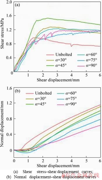
Figure 4 Shear behavior of unbolted and bolted joint specimens with inclined bolt at initial normal stress of 0.5 MPa (CNL tests):
Figure 5 shows the variation of typical shear parameters of unbolted and bolted specimens with different bolt inclination angles under the CNL conditions. In Figure 5, the shear parameter of ��=0�� corresponds to the test result of unbolted joints. The effect of bolt inclination angle on maximum shear stress was shown in Figure 5(a). The maximum shear stress ��m first increased and then decreased with the increase of bolt inclination angle. When �� increased from 30�� to 45��, the maximum shear stress increased by 21.4% from 1.26 to 1.53 MPa. However, as �� further increased, the maximum shear stress gradually decreased. When �� increased from 45�� to 90��, the maximum shear stress decreased by 26.8% from 1.53 to 1.12 MPa. In addition, the decreasing rate declined with the increase of ��. The maximum shear stress of the bolted joint was always larger than that of unbolted one (0.99 MPa). Compared with unbolted joint, the maximum shear stress of the bolted joint increased by 34.1% (30��), 54.6% (45��), 24.7% (60��), 20.9% (75��) and 19.2% (90��). Therefore, it��s concluded that the optimization of the bolt inclination angle is necessary, and the optimal bolt inclination angle is 45�� under the CNL conditions for this experimental study. This observation is similar to that made by GRASSELLI [22]. Their research results demonstrated that the maximum load mobilized by the bolt occurs for an initial bolt inclination angle to the bolt in the range of 30�� to 60��.
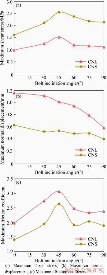
Figure 5 Effect of bolt inclination angle on:
The maximum normal displacement vm is also related to ��. Figure 5(b) shows the relationship between maximum normal displacement and ��. The maximum normal displacement of bolted joint specimens monotonously decreased as the increase of ��, suggesting that joint opening is best restricted by installing the bolt perpendicular to the joint plane. When �� increased from 30�� to 90��, the maximum normal displacement decreased by 46.8% from 1.11 to 0.59 mm. The maximum normal displacement of the bolted joint was always smaller than that of unbolted one (1.16 mm). Compared with unbolted joint, the maximum normal displacement of the bolted joint decreased by 4.2% (30��), 12.8% (45��), 18.7% (60��), 31.8% (75��) and 49.5% (90��). Under CNL conditions, dilation isn��t restricted because normal load keeps constant during the shearing process. However, under CNS conditions, normal load varies as normal displacement, dilation would be suppressed and shear strength would be improved due to increased normal load during the shearing process. Thereby, the difference in normal displacement of bolted joint with different bolt inclinations can cause the difference in applied normal stress on the shear plane under CNS conditions. It is expected that applied normal stress under CNS conditions decreased as the increase of bolt inclination angle based on existing test results under CNL conditions. Considering that CNS boundary condition is more suitable to simulate the shear behavior of bolted rough joints than CNL boundary condition, it��s necessary to conduct CNS shear test of bolted joint specimens with different bolt inclinations. The test results under CNS conditions would be discussed in the next section.
Figure 5(c) shows the relationship between the maximum friction coefficient fm and ��. The friction coefficient is defined as the shear stress over normal stress. Therefore, the changing trend of the maximum friction coefficient and maximum shear stress is consistent under the CNL conditions.
3.3 CNS shear test results of bolted joints
In order to study the shear behavior of unbolted and bolted joint specimens with different bolt inclination angles under the CNS conditions, CNS shear tests were carried out at the initial normal stress of 0.5 MPa and normal stiffness of 2 GPa/m. The shear test results of unbolted and bolted joint specimens with different bolt inclination angles under the CNS conditions are illustrated in Figure 6. Similar to the test results in the CNL tests, the shear strength and maximum friction coefficient were improved and normal displacement was suppressed after bolting under the CNS conditions. The curves of shear stress-shear displacement and friction coefficient-shear displacement displayed strain-hardening and strain- softening behavior under the CNS conditions, respectively. Under both CNL and CNS conditions, the shape of normal displacement-shear displacement curves was similar. The shear stress path was vertical under the CNL conditions; however, it became extremely complicated under the CNS conditions due to varied normal stress. At the quasi-elastic stage, the shear stress increased sharply, and the normal stress first slightly decreased and then increased until the yield shear stress was reached. At the strain-hardening stage, shear stress increased slowly with normal stress at an approximately constant rate.
The influence of �� on the maximum shear stress, maximum dilation displacement, and maximum friction coefficient under the CNS conditions is also shown in Figure 5. The changing trend of maximum shear stress, maximum dilation displacement, and maximum friction coefficient with �� under the CNS conditions tended to coincide with that under the CNL conditions, suggesting that CNL test results can be used to determine the optimal bolt inclination angle although it underestimates the shear strength because normal stiffness is ignored. As excepted, the maximum shear stress under the CNS conditions was much greater than that under the CNL conditions, while the maximum normal displacement and maximum friction coefficient under the CNS conditions were smaller than that under the CNL conditions irrespective of bolting or not due to the increased normal stress, as given in Table 2.
3.4 Comparison of test results under CNL and CNS conditions
In order to study the effect of boundary conditions on the mechanical and deformation characteristics of bolted joints with different inclined bolts, the change rate of the mechanical and deformation parameters under the CNL and CNS conditions were compared. The maximum shear stress variation rate of the bolted joint was defined as follows:
 (4)
(4)
where ��sl and ��ss are the maximum shear stress of bolted joints with the same bolt inclination angle under the CNL and CNS conditions, respectively; ��v is the maximum shear stress variation rate of bolted joints.
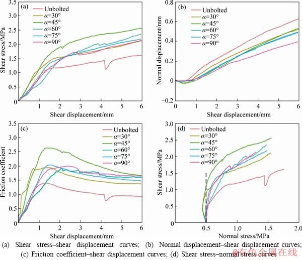
Figure 6 Shear behavior of unbolted and bolted joint specimens with inclined bolt at initial normal stress of 0.5 MPa and normal stiffness of 2 GPa/m (CNS tests):
Table 2 Typical shear parameters of joints with and without bolts under CNL and CNS conditions
Similar to the definition of the maximum shear stress variation rate, the variation rate of the maximum normal displacement and the maximum friction coefficient can be defined in the same way as Eq. (1). The calculated results of the variation rate are presented in Table 3 and Figure 7. In Figure 7, the variation rate of ��=0�� was obtained from the test result of unbolted joints where vv and fv are the variation rate of the maximum normal displacement and maximum friction coefficient, respectively.
As shown in Table 3, the maximum shear stress variation rates are 62.6% (unbolted joint), 65.6% (30��), 67.3% (45��), 93.5% (60��), 87.2% (75��) and 92.0% (90��), respectively. When �� was less than 45��, the maximum shear stress increased by approximately 65.2%, nevertheless it increased by approximately 90.9% when �� was more than 45��. For the maximum friction coefficient variation rate, it shows the non-linear change trend of first increase then stability accompanied by minor fluctuations. From Figure 7(b), it can be noted that the maximum normal displacement variation rate increased as bolt inclination angle for bolted joints, which revealed that higher bolt inclination angle could lead to a smaller difference in the maximum normal displacement under the CNL and CNS conditions.
Table 3 Variation rate of shear parameters of joints due to transformation of boundary conditions
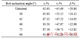
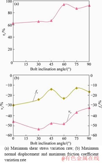
Figure 7 Effect of bolt inclination angle on variation rate of shear mechanical and deformation parameters:
3.5 Failure characteristic
Asperity degradation and damage are related to the shear behavior of rock joints. To better understand the shear behavior of bolted joints, the failure characteristic of bolted joints under CNL and CNS conditions were analyzed. After shear tests, the bolt was pulled out from joint specimens. The failure surfaces of bolted joints with �� of 60�� after the shear test are shown in Figure 8. It can be seen that the shear failure of the bolted joint only occurred in local areas of the joint surface. Two typical asperity failure mode was identified as crushed grain and fragment during this experiment. Pulverized and crushed grain resulting from shearing abrasion and shearing off the second-order asperity were primary asperity failure mode for bolted joint, as shown in a red ellipse. The magnified view of the crushed grain and intact grain were shown in the blue rectangle, where the surface of crushed grain is rough while the intact grain is smooth. In addition, broken fragments resulting from shear and tension failure of the asperities were also observed, as shown in the green rectangle.
Shear slide mode and shear off mode were dominant failure modes under the CNL and CNS conditions at the initial normal stress of 0.5MPa, respectively (Figure 8). Compared with the joint surface after shear test under the CNL conditions, asperity degradation and damage were more severe under the CNS conditions. It was found that the area of the crushed grain and the size of the fragment were more significant under the CNS conditions.
4 Discussion
The shear resistance provided by rock bolt consists of two parts: cohesion enhancement effect and friction enhancement effect. Generally, cohesion enhancement effect always much larger than the friction enhancement effect [35]. With the increase of bolt inclination angle, both cohesion and friction enhancement effects increased first and then decreased. Furthermore, LIU et al [36] concluded that the maximum shear stress could be obtained when bolt inclination angle is equal to basic friction angle. Therefore, the maximum shear stress increased first until �� reached basic friction angle and then decreased with increased bolt inclination angle, which can be used to explain the relationship between the maximum shear stress and bolt inclination angle in this study.
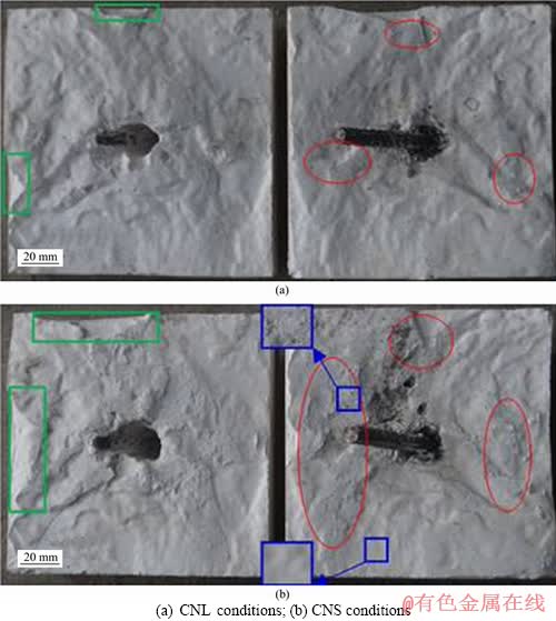
Figure 8 Surface profiles of bolted joints with bolt inclination angle �� of 60�� after shearing:
An appropriate evaluation of the JRC and joint wall compression strength (JCS) is vital in practice to accurately determine the shear behaviors of rock joints [37-39]. The morphology and mechanical properties of rock joints are two essential factors that influence the shear strength and deformation of rock joints with and without bolt. The study conducted by CHEN et al [17] suggested that the reinforcement effect varied as JRC in the CNL tests. In addition, JRC has a more pronounced influence on the shear behavior under the CNS conditions than that under the CNL conditions. Hence, the bolted joints with different JRCs under the CNS condition need to be investigated in the future. A comparatively soft plaster was used to simulate natural rock joints in this context, which has been used widely in many previous studies [40, 41]. However, it should be emphasized that this kind of model materials do not simulate the shear behaviors of hard rock, where the shear failure of rock bolt may occur [42], suggesting that the shear behaviors of bolted rock joints with higher JCS also need to be evaluated in future experimental studies.
5 Conclusions
In the present study, a new artificial molding method for preparing bolted joint specimens with inclined bolt was proposed based on 3D scanning and printing technology. A series of bolted joint specimens with the bolt inclination angle of 30��, 45��, 60��, 75�� and 90�� were prepared using this method. The shear behavior of bolted joint under both CNL and CNS conditions was investigated, and the joint surface failure mode was analyzed. The main conclusions are as follows:
1) After bolting, the maximum shear stress of rock joints was improved significantly, especially under the CNS conditions, while the normal displacement was suppressed.
2) The bolt inclination angle influences the strength and deformation parameters of bolted joints. The maximum shear stress and maximum friction coefficient under both CNL and CNS conditions show similar non-linear change trend of first increase then decrease, where the peak was reached when bolt inclination angle �� was 45��, which is the optimal bolt inclination angle irrespective of boundary conditions. The maximum normal displacement decreased monotonously with the increase of ��.
3) Compared with the test results under the CNL conditions, the maximum shear stress was larger under the CNS conditions, whereas the maximum normal displacement and friction coefficient were smaller, revealing that ignoring normal stiffness would lead to an underestimation of shear strength and an overestimation of shear dilatancy of rock joints.
4) Bolted joints show shear slide and shear off failure mode under the CNL and CNS conditions at the initial normal stress of 0.5 MPa, respectively. The area of the crushed grain and the size of the fragment under the CNS conditions became more extensive than those under the CNL conditions.
References
[1] LI C C, STILLBORG B. Analytical models for rock bolts [J]. International Journal of Rock Mechanics and Mining Sciences, 1999, 36(8): 1013-1029. DOI: 10.1016/S1365- 1609(99)00064-7.
[2] CHEN Y. Experimental study and stress analysis of rock bolt anchorage performance [J]. Journal of Rock Mechanics and Geotechnical Engineering, 2014, 6(5): 428-437. DOI: 10.1016/j.jrmge.2014.06.002.
[3] LI Xu-wei, NEMCIK J, MIRZAGHORBANALI A, AZIZ Y N, RASEKH H. Analytical model of shear behaviour of a fully grouted cable bolt subjected to shearing [J]. International Journal of Rock Mechanics and Mining Sciences, 2015, 80: 31-39. DOI: 10.1016/j.ijrmms.2015. 09.005.
[4] KANG Hong-pu, WU Yong-zheng, GAO Fu-qiang, LIN Jian, JIANG Peng-fei. Fracture characteristics in rock bolts in underground coal mine roadways [J]. International Journal of Rock Mechanics and Mining Sciences, 2013, 62: 105-112. DOI: 10.1016/j.ijrmms. 2013.04.006.
[5] BLANCO M L, TIJANI M, HADJ-HASSEN F, NOIRET A. Assessment of the bolt-grout interface behaviour of fully grouted rockbolts from laboratory experiments under axial loads [J]. International Journal of Rock Mechanics and Mining Sciences, 2013, 63: 50-61. DOI: 10.1016/j.ijrmms. 2013.06.007.
[6] JALALIFAR H. An analytical solution to predict axial load along fully grouted bolts in an elasto-plastic rock mass [J]. Journal of the Southern African Institute of Mining and Metallurgy, 2011, 111(11): 809-814. http://www.scielo.org. za/scielo.php?script=sci_arttext&pid=S2225-62532011001100014.
[7] CHEN Jian-hang, HAGAN P C, SAYDAM S. Parametric study on the axial performance of a fully grouted cable bolt with a new pull-out test [J]. International Journal of Mining Science and Technology, 2016, 26(1): 53-58. DOI: 10.1016/j.ijmst.2015.11.010.
[8] KILIC A, YASAR E, CELIK A G. Effect of grout properties on the pull-out load capacity of fully grouted rock bolt [J]. Tunnelling and Underground Space Technology, 2002, 17(4): 355-362. DOI: 10.1016/S0886-7798(02)00038-X.
[9] LI C C, KRISTJANSSON G, HOIEN A H. Critical embedment length and bond strength of fully encapsulated rebar rockbolts��[J]. Tunnelling and Underground Space Technology, 2016, 59: 16-23. DOI: 10.1016/j.tust.2016. 06.007.
[10] THENEVIN I, BLANCO-MARTIN L, HADJ-HASSEN F, SCHLEIFER J, LUBOSIK Z, WRANA A. Laboratory pull-out tests on fully grouted rock bolts and cable bolts: Results and lessons learned [J]. Journal of Rock Mechanics and Geotechnical Engineering, 2017, 9(5): 843-855. DOI: 10.1016/j.jrmge.2017.04.005.
[11] LI C C. Principles of rockbolting design [J]. Journal of Rock Mechanics and Geotechnical Engineering, 2017, 9(3): 396-414. DOI: 10.1016/j.jrmge.2017.04.002.
[12] ZHAO Lian-heng, TAN Yi-gao, NIE Zhi-hong, YANG Xin-ping, HU Shi-hong. Variation analysis of ultimate pullout capacity of shallow horizontal strip anchor plate with 2-layer overlying soil based on nonlinear M-C failure criterion [J]. Journal of Central South University, 2018, 25(11): 2802-2818. DOI: 10.1080/19648189.2019.1626288.
[13] ZHANG Chuan-qing, CUI Guo-jian, ZHOU Hui, LIU Li-peng, LIU Zhen-jiang, LU Jing-jing, CHENG Guang-tan. Experimental study on shear and deformation characteristics of the rod-grout interface [J]. Chinese Journal of Rock Mechanics and Engineering, 2018, 37(4): 820-828. DOI: 10.13722/j.cnki.jrme.2017.1090. (in Chinese)
[14] ZHANG Chuan-qing, CUI Guo-jian, DENG Liang, ZHOU Hui, LU Jing-jing, DAI Feng. Laboratory investigation on shear behaviors of bolt-grout interface subjected to constant normal stiffness [J]. Rock Mechanics and Rock Engineering, 2020, 53(3): 1333-1347. DOI: 10.1007/s00603-019- 01983-6.
[15] YOSHINAKA R, SAKAGUCHI S, SHIMIZU T, ARAI H, KATO E. Experimental study on the rock bolt reinforcement in discontinuous rocks [C]// 6th ISRM Congress. Australia: International Society for Rock Mechanics and Rock Engineering, 1987: 1325-1328.
[16] SPANG K, EGGER P. Action of fully-grouted bolts in jointed rock and factors of influence [J]. Rock Mechanics and Rock Engineering, 1990, 23(3): 201-229. DOI: 10.1007/BF01022954.
[17] CHEN Na, ZHANG Xiao-bo, JIANG Qing-hui, FENG Xi-xia, WEI Wei, YI Bing. Shear behavior of rough rock joints reinforced by bolts [J]. International Journal of Geomechanics, 2018, 18(1): 04017130. DOI: 10.1061/ (ASCE)GM.1943-5622.0001048.
[18] WANG Gang, ZHANG Yong-zheng, JIANG Yu-jing, LIU Pei-yun, GUO Yan-shaung, LIU Jian-kang, MA Ming, WANG Ke, WANG Shu-gang. Shear behaviour and acoustic emission characteristics of bolted rock joints with different roughnesses [J]. Rock Mechanics and Rock Engineering, 2018, 51(6): 1885-1906. DOI: 10.1007/ s00603-018-1438-9.
[19] WU Xue-zhen, JIANG Yu-jing, LI Bo. Influence of joint roughness on the shear behaviour of fully encapsulated rock bolt [J]. Rock Mechanics and Rock Engineering, 2018, 51(3): 953-959. DOI: 10.1007/s00603-017-1365-1.
[20] GHADIMI M, SHAHRIAR K, JALALIFAR H. Analysis profile of the fully grouted rock bolt in jointed rock using analytical and numerical methods [J]. International Journal of Mining Science and Technology, 2014, 24(5): 609-615. DOI: 10.1016/j.ijmst.2014.07.009.
[21] LI Xu-wei, AZIZ N, MIRZAGHORBANALI A, NEMCIK J. Comparison of the shear test results of a cable bolt on three laboratory test apparatuses [J]. Tunnelling and Underground Space Technology, 2017, 61: 82-89. DOI: 10.1016/j.tust. 2016.10.003.
[22] GRASSELLI G. 3D behaviour of bolted rock joints: Experimental and numerical study [J]. International Journal of Rock Mechanics and Mining Sciences, 2005, 42(1): 13-24. DOI: 10.1016/j.ijrmms.2004.06.003.
[23] HAAS C J. Shear resistance of rock bolts [J]. Trans Soc Min Eng AIME, 1976, 260(1): 32-41. DOI: 10.1016/0148- 9062(76)91671-5.
[24] SHRIVASTAVA A K, RAO K S. Shear Behaviour of rock joints under CNS boundary conditions [J]. Geotech Geol Eng, 2013, 33(5): 961-964. DOI: 10.1007/s10706-015-9896-2.
[25] JIANG Yu-jing, XIAO Jun, TANABASHI Y, MIZOKAMI T. Development of an automated servo-controlled direct shear apparatus applying a constant normal stiffness condition [J]. International Journal of Rock Mechanics and Mining Sciences, 2004, 41(2): 275-286. DOI: 10.1016/j.ijrmms. 2003.08.004.
[26] LEE Y K, PARK J W, SONG J J. Model for the shear behavior of rock joints under CNL and CNS conditions [J]. International Journal of Rock Mechanics and Mining Sciences, 2014, 70: 252-263. DOI: 10.1016/j.ijrmms.2014. 05.005.
[27] GU X F, SEIDEL J P, HABERFIELD C M. Direct shear test of sandstone-concrete joints [J]. International Journal of Geomechanics, 2003, 3(1): 21-33. DOI: 10.1061/(ASCE) 1532-3641(2003)3:1(21).
[28] SHANG Jun-long, ZHAO Zhi-ye, MA Shu-qi. On the shear failure of incipient rock discontinuities under CNL and CNS boundary conditions: Insights from DEM modelling [J]. Engineering Geology, 2018, 234: 153-166. DOI: 10.1016/ j.enggeo.2018.01.012.
[29] FAN Wen-chen, CAO Ping, LONG Long. Degradation of joint surface morphology, shear behavior and closure characteristics during cyclic loading [J]. Journal of Central South University, 2018, 25(3): 653-661. DOI: 10.1007/��s11771-018-3768-x.
[30] INDRARATNA B, AZIZ N, DEY A. Modeling of bolted joint behaviour under constant normal stiffness conditions��[C]// An International Conference on Geotechnical & Geological Engineering. Pennsylvania, USA, 2000. http://ro.uow.edu.au/cgi/viewcontent.cgi?article=1714&context=engpapers.
[31] BARTON N. Review of a new shear-strength criterion for rock joints [J]. Engineering Geology, 1973, 7(4): 287-332. DOI: 10.1016/0013-7952(73)90013-6.
[32] TSE R, CRUDEN D M. Estimating joint roughness coefficients��[J]. International Journal of Rock Mechanics and Mining Sciences, 1979, 16(5): 303-307. DOI: 10.1016/0148-9062(79)90241-9.
[33] TATONE B S A, GRASSELLI G. A new 2D discontinuity roughness parameter and its correlation with JRC��[J]. International Journal of Rock Mechanics and Mining Sciences, 2010, 47(8): 1391-1400. DOI: 10.1016/ j.ijrmms.2010.06.006.
[34] FICKER T. Fractal properties of joint roughness coefficients [J]. International Journal of Rock Mechanics and Mining Sciences, 2017, 94(3): 27-31. DOI: 10.1016/j.ijrmms.2017. 02.014.
[35] LI Yu-zong, LIU Cai-hua. Experimental study on the shear behavior of fully grouted bolts [J]. Construction and Building Materials, 2019, 223: 1123-1134. DOI: 10.1016/j.conbuildmat.2019.06.207.
[36] LIU Cai-hua, LI Yu-zong. Analytical study of the mechanical behavior of fully grouted bolts in bedding rock slopes [J]. Rock Mechanics and Rock Engineering, 2017, 50(9): 2413-2423. DOI: 10.1007/s00603-017-1244-9.
[37] SOW D, RIVARD P, PEYRAS L, MORADIAN Z A, BACCONNET C, BALLIVY G. Comparison of joint shearing resistance obtained with the Barton and Choubey criterion and with direct shear tests��[J]. Rock Mechanics and Rock Engineering, 2016, 49(8): 3357-3361. DOI: 10.1007/s00603-015-0898-4.
[38] DU Shi-gui, HU Yun-jin, HU Xiao-fei, GUO Xiao. Comparison between empirical estimation by JRC-JCS model and direct shear test for joint shear strength��[J]. Journal of Earth Science, 2011, 22(3): 411-420. DOI: 10.1007/s12583-011-0193-6.
[39] BARTON N. The shear strength of rock and rock joints��[J]. International Journal of Rock Mechanics and Mining Sciences, 1976, 13(9): 255-279. DOI: 10.1016/0148-��9062(76)90003-6.
[40] NIKTABAR S M M, RAO K S, SHRIVASTAVA A K. Effect of rock joint roughness on its cyclic shear behavior��[J]. Journal of Rock Mechanics and Geotechnical Engineering, 2017, 9(6): 1071-1084. DOI: 10.1016/j.jrmge.2017.09.001.
[41] SHANG Jun-long, YOKOTA Y, ZHAO Zhi-ye, DANG Wen-gang. DEM simulation of mortar-bolt interface behaviour subjected to shearing��[J]. Construction and Building Materials, 2018, 185: 120-137. DOI: 10.1016/ j.conbuildmat.2018.07.044.
[42] LI C C. Field observations of rock bolts in high stress rock masses [J]. Rock Mechanics and Rock Engineering, 2010, 43(4): 491-496. DOI: 10.1007/s00603-009-0067-8.
(Edited by ZHENG Yu-tong)
���ĵ���
��������غͳ�����ն������²�ͬê�̽Ƕȼ�ê��������ļ��������о�
ժҪ��ê�˹㷺Ӧ���ڽ�������ӹ������ܹ�������������������Ŀ������ܡ�Ϊ�о�ê����Ǻͷ���߽������Լ�ê��������������ܵ�Ӱ�죬���IJ����˻���3Dɨ��ʹ�ӡ���������ͼ�ê���������Ʊ���������һ������ͬê�̽Ƕȵļ�ê��������������չ�˳�������غͳ�����ն������µ�ֱ�Ӽ������顣�����������װê�˺��������ڷ��Σ������濹��������������������ê�̽Ƕȵ���������Ӧ�������Ħ��ϵ����������������С�ķ����Ա仯���ƣ��������λ�Ƶ�����С����������ê�̽Ƕȡ��Ա�CNL��CNS����������CNS�����¼�ê����������и��ߵļ���ǿ���Լ����͵ķ���λ�ƺ�Ħ��ϵ�������⣬CNS���������������˸������ء�
�ؼ��ʣ�ê�̽������壻ê����ǣ���������أ�������նȣ�ֱ�����飻��������
Foundation item: Project(U1865203) supported by the Key Projects of the Yalong River Joint Fund of the National Natural Science Foundation of China; Project(51279201) supported by the National Natural Science Foundation of China; Projects(2019YFC0605103, 2019YFC0605100) supported by the National Key R&D Program of China
Received date: 2019-09-17; Accepted date: 2019-11-11
Corresponding author: ZHANG Chuan-qing, PhD, Professor; Tel: +86-27-87197913; E-mail: cqzhang@whrsm.ac.cn; ORCID: 0000- 0002-7990-789X
Abstract: Rock bolts are widely used in rock engineering projects to improve the shear capacity of the jointed rock mass. The bolt inclination angle with respect to the shear plane has a remarkable influence on the bolting performance. In this study, a new artificial molding method based on 3D scanning and printing technology was first proposed to prepare bolted joints with an inclined bolt. Then, the effects of the bolt inclination angle and boundary conditions on the shear behavior and failure characteristic of bolted joints were addressed by conducting direct shear tests under both CNL and CNS conditions. Results indicated that rock bolt could significantly improve the shear behavior of rock joints, especially in the post-yield deformation region. With the increase of bolt inclination angle, both the maximum shear stress and the maximum friction coefficient increased first and then decreased, while the maximum normal displacement decreased monotonously. Compared with CNL conditions, the maximum shear stress was larger, whereas the maximum normal displacement and friction coefficient were smaller under the CNS conditions. Furthermore, more asperity damage was observed under the CNS conditions due to the increased normal stress on the shear plane.
