
J. Cent. South Univ. (2016) 23: 68-76
DOI: 10.1007/s11771-016-3050-z

Effect of gear teeth finishing method on properties of teeth surface layer and its resistance to pitting wear creation
Jan Zwolak, Arkadiusz Palczak
Department of Mechanics and Mechanical Engineering, Faculty of Mathematics and Natural Sciences,
The University of Rzesz��w, Rejtana ave. 16C, Rzesz��w, 35-959, Poland
 Central South University Press and Springer-Verlag Berlin Heidelberg 2016
Abstract:
This work presented the characteristics of two gear teeth finishing methods, due to the properties of gear teeth surface layer obtained at the tooth working depth. These methods are: 1) the teeth carburization, hardening to a hardness of HRC 60-62 and then grinding, 2) the soft gear shaving as the final mechanical treatment and then carburizing and hardening to the hardness of HRC60-62. This work included the test results of the contact fatigue strength carried out on the circulating power system. The Wohler curves were plotted due to the obtained results, as the basis for the practical evaluation of the considered gear finishing methods. The parameters like volume distribution of the voids, content of the retained austenite, compressive residual stress value, but also the results of contact fatigue strength tests, are more favorable for the teeth shaving method than for the teeth grinding method.
Key words:
gear teeth; finishing treatment; surface layer; contact fatigue strength; pitting��
1 Introduction
The whole technological process, particularly its finishing phase is an important step towards creation of the gears surface layer, which should lead into the improvement of tribological wear resistance. The issues related to the finishing treatment were presented by Chen et al [1] about their experiments and simulations of the gears production by the grinding technology in terms of obtaining different roughness parameter values. The roughness as a parameter of the surface layer, has a significant effect on the quality of lubricating effect and thus the conditions of the friction and tribological wear of the gear teeth contact surfaces. In turn, Lv and YANG [2] analyzed the process of the gear teeth shaving as the mechanical treatment. The results of their experiments show that machining with this method allows to obtaining good parameters of the surface geometrical structure for the gear teeth. The topography of the gear teeth surface after three different finishing methods: after finishing treatment by grinding, after finishing treatment by shaving and after finishing treatment by honing, were investigated and described in Ref. [3]. Depending on the finishing method, obtained surface geometrical structure significantly affects the lubricating conditions (lubricant retention volume) and thus the tribological effects during exploitation of the gears. Aslantas et al [4] provided the analysis of the pitting wear resistance of gears made of ductile iron after heat treatment. Their research was conducted on the circulating power test bench, with a constant distance between axles of the gears. This distance was equal to 91.5 mm.
The experimental tests over the influence of the surface layer parameters on exploitation processes were conducted by Zwolak [5]. He examined the impact of fatigue strength of the contact on gear teeth, made of different grades of steel (five grades of steel were examined) with carburizing and hardening treatment. During the experimental tests, it is necessary to consider that the residual (internal) stresses and contact (external) stresses coming from the external load in the form of forces between teeth are adding up. The forces between teeth change over meshing tooth depth with the change of the contact point position and the number of teeth which are in engagement. The contact stresses also depend on many other factors, such as modification of the tooth profile and the flank pitch line, summation of implementing errors with the elastic deformations of the shafts and teeth of the engaged gears. However, these factors are not considered in the present work.
In the calculation procedures of contact stresses of gears the most important factor is contact fatigue resistance sHlim, which is determined by the properties of the surface layer. The order of operations in the process of finishing technologies, as well as the selected method has a significant effect on the properties of the surface layer, due to this fact that the strength calculations should always include the influence from the finishing methods, with the knowledge of the properties of the surface layer and the fatigue resistance of the contact sHlim, it is possible to make the evaluation of the different finishing methods.
The literature shows that many interesting studies on the constitution of the teeth surface layer of the gears during the finishing process were conducted. However, there are not many publications that cover the whole problem of the effect of finish processing on the condition of the tooth side surface layer in conjunction with the fatigue strength tests of contact area and presentation of the results of these studies.
2 Characteristics of surface layer of investigated gear teeth
During our researches, the tests were carried out on the active flanks of the teeth, after two different methods of the finishing treatment, named as the technologies A and B. Finishing treatment realized according to the Technique A carried out in the following order: teeth were carburized, hardened and then ground. According to Technique B the finishing treatment was realized in the following order: gear teeth shaving was the final machining treatment, after those teeth were carburized and then hardened.
Investigated gears were made of SAE 8620 steel. Carburizing and hardening were carried out on technological line provided by the Surface Combustion Division Midland Ross Corporation company. The following parameters were used: active carbonizing under temperature of 925 ��C, after that lowering the temperature to 840 ��C and then hardening from this temperature. In the final phase of the thermo-chemical treatment, annealing was carried out at the temperature of 180 ��C. Grinding of the teeth surfaces was carried out on a Niles grinding machine, using corundum grinding wheel, with the following parameters: speed n=1500 min-1, number of jumps I=71 min-1, cutting depth g=0.04 mm. Shaving was performed on Red Ring diagonal shaving machine, using the following parameters: shaving speed n=63 min-1, feed p=58 mm/min, and the number of passes i=6. The topographies of the surfaces obtained during both finishing technologies (A and B) are shown in Fig. 1.
Experimental studies investigating the process of the pitting wear formation on the gear teeth were conducted by Duzcukoglu and Imrek [6]. The subjects of their research were gears made of the 8620 steel, carburized and hardened up to HRC 58. They analyzed the contact stresses distribution at the height of the active gear tooth, making a distinction between two areas: area of the two-pair teeth meshing and area of one-pair teeth meshing. Glodez et al [7] considered the process of the wear creation on teeth sides through computer simulation and experimental researches. The computer simulations were conducted by the finite elements method and experimental tests were taken on the circulating power test bench.
Tang and Liu [8] also analyzed the contact stress, occurring in the meshing of gears, on the analytical and numerical ways. The analytical method was conducted with the use of Hertz theory, while the numerical simulations were conducted by the finite element method (FEM).
The grinding method with the use of shaped disc, made of a plastic binder was described by Heinzel and Wagner [9]. Their tests were carried out on gears made of 16MnCr5 steel, hardened up to HRC63. This allowed to obtain very small surface roughness (Rz=0.8-1.9 ��m) and the favorable state of residual stresses in the surface layer, i.e. the negative compressive stresses.
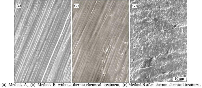
Fig. 1 Teeth face surface topography:
The clear difference between the topographies of the surface, obtained during the different finishing methods could be noticed in Fig. 1. Surface structure shown in Fig. 1(a) is the result of grinding of the teeth according to the Niles method and it has anisotropy structure with well-oriented micro-section scratches, mapped by the abrasive grains placed with random arrangement in the abrasive disk. Figure 1(b) shows the tooth surface after tooth shaving, before thermo-chemical treatment. In this case, the structure of the surface has much smaller anisotropy than the surface after grinding. On the other hand, Fig. 1(c) shows clearly that the surface structure anisotropy after thermo-chemical treatment very decreases. The reduce of anisotropy could be explained by the fact that process of carburizing and hardening, at a temperature of about 925 ��C, causes oxidation of the surface roughness formed during teeth shaving.
During our studies over the surface geometrical structure, the measuring device TalyScan produced by Taylor Hobson company and specialized computer software-TalyMap were used. The research methodology given by OCZO and Lubimov [10] was applied to the measurements. According to this methodology, volume surface ratios of tooth involute contour were considered. These ratios are characterized by interdependencies of the material volume ��m: and the void volume ��v��, as shown in Fig. 2.
the axis of ordinates is set aside the volume of the void and material, expressed as a percentage of the total volume of the surface structure, whereas the axis of abscissa is set ordinate of the height of the St profile, also expressed as the percentage. The three-dimensional images illustrate the final structure of the cross-sectioned area, at the different levels: level 1, 0%, level 2, 20%, Level 3, 40%, Level 4, 60%, Level 5, 80%.
The quantitative analysis of the surface structure volume is carried out by appropriate coefficients: 1) the factor of the material volume at the current given level- Smmr-referred as the material volume reference at a present level to the material volume at the zero level (min). 2) the factor of the void volume at the current given level-Smvr-referred as the void volume reference at a present level to the void volume at the 100% level (max).
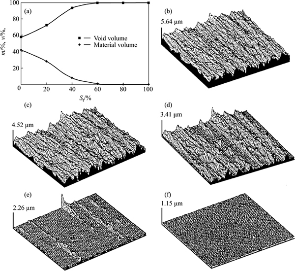
Fig. 2 Distribution of volumes of material ��m�� and voids ��v�� as a function of parameter St (a) and level 1 (b), 0%, level 2, 20% (c), Level 3, 40% (d), Level 4, 60% (e) and Level 5, 80% (f)
With use of the specialized TalyMap software, the characteristics of the surface geometrical structure were developed and expressed, by a power spectral density function-APSD (areal power spectral density) and also by the autocorrelation function AACF (areal autocorrelation function). These functions with their graphical illustration are shown in Fig. 3.
With the knowledge about the function of the power spectral density, it is possible to separate specified modal values of the surface geometrical structure (Surface 1 in Fig. 3), or determine the randomness degree for the tested structure. In Fig. 3 it can be clearly seen multiple modal values on the Surface 2, and almost random noise on the Surface 4.
The function of the autocorrelation can be regular harmonic, in the case of the surface geometrical structure with the strongly-expressed modal value (Surface 1 in Fig. 3), fading with the lesser or greater extent, depending on the density of occurring modal values (as it is illustrated on the Surface 2 and the Surface 3 in Fig. 3). It may also take the flat form, with more or less prominently exposed symmetrically central peak, even into the processes approximating to the random noise (Surface 4 in Fig. 3). Additionally, the function of the autocorrelation shown in Fig. 3 allows for an evaluation of the degree of isotropy or anisotropy of the surface.
3 Characteristic of surface layer
The surface layer at the meshing tooth depth has been characterized by the measurement of the retained austenite content, measurement of the residual stresses and the measurement of the microhardness at the cross-section of carburized layer. The Roentgen diffraction method with the filtered K��1 radiation coming from the cobalt lamp has been used during the studies of residual austenite content. Reflections of the {111}�� from the austenite and {110}�� from the martensite were recorded. The retained austenite content in the surface layer of the ground teeth (Technique A) was equal to V��=46.2%. In the case of shaved teeth (Technique B) it was equal to V��=19.9%.
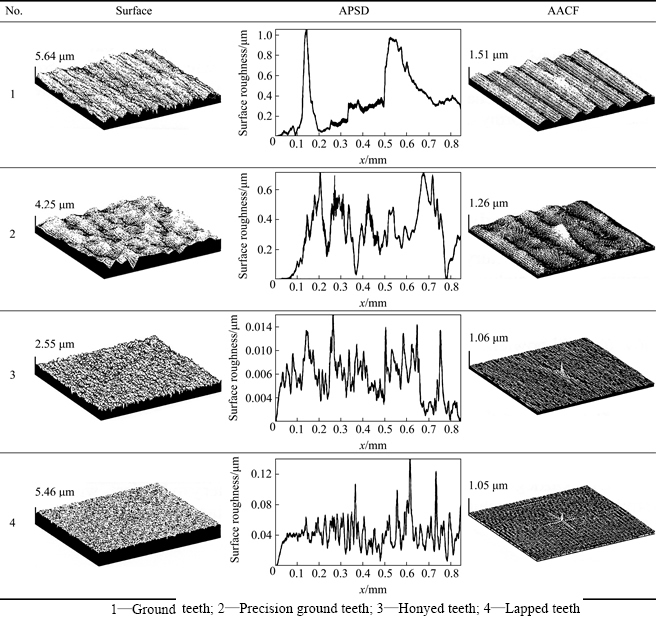
Fig. 3 Power spectral density functions and autocorrelation functions characterizing surfaces of gear teeth after treatment:
Residual stresses were measured at three characteristic points of the tooth face. These points with the reference system of the components of the stresses sx and sy are shown in Fig. 4.
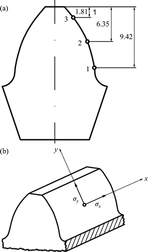
Fig. 4 location of measurement points (a) and reference system for stress components (b)
Measurement of stresses was performed on X-ray diffractometer TUR-M62 and goniometer HZG-3. For this purpose the method of measuring sin2�� was used. It allows for the measurement of the stresses components sx and sy. The measurement results in the form of residual stresses expressed according to the technologies A and B are listed in Tables 1 and 2.
An important parameter of the surface layer, with the high impact on the contact fatigue strength is the distribution of the microhardness in the cross-section of the carburized layer. Microhardness distribution graph was made by the use of measurement results obtained in the cross-section perpendicular to the involute surface of the tooth, in the pitch diameter of the gear. The measurement was performed on a Zwick apparatus, using the Vickers intender. Imprints were made with the measurement interval of 0.2 mm and the load of 50 N. Microhardness distribution curve for the ground teeth(Technique A) is shown in Fig. 5.
Table 1 Stresses components for grinding teeth according to technique A
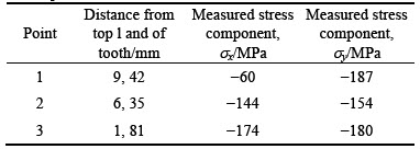
Table 2 Stresses components for shaving teeth according to technique B
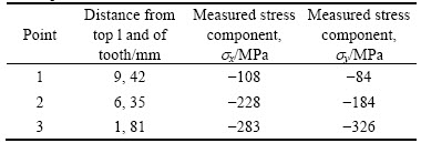
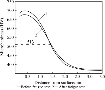
Fig. 5 Distribution of microhardness in cross-section of carburized layer for ground tooth:
The microhardness distribution curves indicate that in the cross-section of carburized layer, there is an area with the maximum microhardness and it is laying approximately 0.4 mm under the surface. The placement of the layer with the maximum microhardness deeper under surface of the carburized layer is caused by the fact that close to the surface is the largest amount of the retained austenite, of which microhardness has less value than in the case of the martensite as the dominant phase.
Curve 1 on Fig. 5 refers to the microhardness of the carburized layer directly after the grinding process (before the fatigue strenght test). The distribution of the curve shows that the microhardness equal to the 513 HV corresponds to the distance of about 1.5 mm, and this distance is taken as the boundary for the carburized layer depth.
Curve 2 on Fig. 5 shows the results obtained during the microhardness measurements for the carburized layer of the tooth after fatigue contact tests, carried out on the test bench with the circulating power system under certain technical conditions. These conditions are characterized by the following parameters: constant load with torque M=796 N��m, contact stress sH=1701 MPa, number of load cycles N=7.1��106, after which pitting wear reached criterial value of 2%.
The studies on microhardnes of the gear teeth machined by Technique B show the similar character of its progress, but with a visible difference in a local maximum just below the surface. The microhardness distribution curve plotted on the basis of the measurements is shown in Fig. 6.
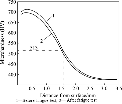
Fig. 6 Distribution of microhardness in cross-section of carburized layer for shaved tooth:
During the comparison of the curves in Figs. 5 and 6 it is possible to notice that the thickness of the carburized layer in accordance to HV513 criterion is greater in Fig. 6, than the one in Fig. 5. A common feature of the curves in Figs. 5 and 6 is the monotonicity of the microhardness characteristic in the range of distances from the surface (up to about 2.5 mm) and up to linear characteristic beyond the 2.5 mm area.
The microhardness distribution curves keep the same shape before and after fatigue tests, but taking the other coordinates in the reference system. These coordinates in the field of monotone characteristic take smaller values for the curves after fatigue test, and the both characteristics take almost equal values in the linear area.
4 Fatigue tests of gears machined according to technique a and technique B
The investigated gears with teeth machined according to the technologies A and B had the following geometrical parameters: number of teeth for gear, z1=17; number of teeth for gear, z2=23; pitch module of the gear, m=6 mm; pressure angle, ��o=20��; addendum modyfication coefficient for gear z1, x1=0.4888; addendum modyfication coefficient for gear z2, x2=0.4600; tooth facewidth for gear z1, b1=16 mm; tooth facewidth for gear z2, b2=17 mm; centre distance, aw=125 mm.
Experimental studies that allowed to determine the numerical value of the contact fatigue strength were carried out on the test bench in the circulating power system, as shown in Fig. 7.
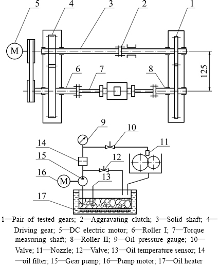
Fig. 7 Test bench scheme of circulating power system:
During the studies on contact fatigue strength sHlim, the criterion of the total 2% loss of the active surface of gears teeth z1=17 and z2=23 was used. This criterion is currently being used in the tribological studies on kinematic links, where the pitting corrosion appears. An example of the 2% criterion of surface pitting wear is shown below:
A1+A2��2% (1)
where
 (2)
(2)
 (3)
(3)
A1 is percentage loss of the active surface for the gear teeth z1 caused by pitting; A2 is percentage loss of the active surface for the gear teeth z2 caused by pitting; Ap1 is the absolute value of pitting wear of the active surface of the gear teeth z1; Ap2 is the absolute value of pitting wear of the active surface of the gear teeth z2; Az1 is the total area of the active surface of the gear teeth z1; Az2 is the total area of the active surface of the gear teeth z2.
The total active surfaces of the teeth for gears z1 and z2 with given geometric parameters are: Az1=3013 mm2, Az2=3887 mm2. Therefore, admissible surface erosions caused by pitting wear due to the 2% criterion are equal to Ap1=30 mm2, Ap2=35 mm2.
Fatigue tests were carried out for 12 pairs of gears, which were loaded with torque at four levels. The begin of the test, cycles for paired gears were carried out with the load greater then expected sustained contact tension, determined by the base number of load cycles NG=50��106. Selection of the fatigue stress level and subsequent calculations by Eqs. (4)-(6) were based on the work of Gurney [11]. Further pairs of gears were exposed to the reduced level of stresses, with the possible value of sustained contact strength. The difference between subsequent levels of the stress was constant and was calculated by
d=Xp+1-Xp (4)
where d is the difference between two adjacent levels of stress; X is the stress value; p the is stress level ratio.
Further reduction of the load leads to a zero level of stresses and under such conditions there will be no occurance of criterial 2% pitting wear, even after exceeding number of the load cycles NG=50��106. At the zero level of the stress, the experimental part of investigation ends and fatigue contact strength factor sHlim could be calculated by
 (5)
(5)
where Xo is the stress value at zero level; A is the sum of the products p �� fp; F is the sum of the frequency of occurrence teeth unworn by 2% pitting.
For the sHlim calculated by Formula (5), it is possible to determine the standard deviation S by
 (6)
(6)
where B is the sum of the products p2��fp.
The observation of the active surfaces of the examined gears teeth at the zero stresses conditions indicates that only certain teeth have noticeable small pitting craters.
Among the many research works in the field of internal stresses and stresses caused by the contact load, as well as retained austenite content, the work of Dommarco et al [12] should be mentioned. Their investigations were conducted on SAE 52100 steel after carbonitriding treatment. They were also examining the fatigue strength of the contact for cylindrical samples with five balls, by the use of the special tester.
What is especially noteworthy are the tests conducted by Onishchenko [13], which are based on numerical simulation models and are related to the wear of the gear teeth surfaces. In the developed numerical models, he toke into account working conditions of the gears and the compatibility with the principles of tribological theories. He also included a misalignment in the terms of the axes of rotation and the temperatures in the meshing zone. According to the operating conditions included in the model, gears lubrication is important because relative thickness of the oil film between the surfaces of the meshed teeth determines their tribological wear resistances.
In our research, the fatigue tests were taken at four levels of fatigue stresses p (from level 0 to level 3) with the corresponding values of the stresses Xp. The results for the gears finished according to the Technique A are listed in Table 3.
Due to the measurement results shown in Table 1, contact fatigue strength sHlim was calculated, and it equals:
 (7)
(7)
While the the standard deviation S is equal to
 (8)
(8)
There was applied the same technique of fatigue tests for the gears shaved, hardened and tempered by the technique B, as in the case of gears made by the technique A. The results of the fatigue tests are listed in Table 4.
Table 3 Fatigue test results for ground teeth made of 8620 SAE steel according to technique A
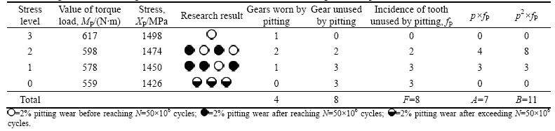
Table 4 Fatigue test results for shaved teeth made of 8620 SAE steel according to technique B
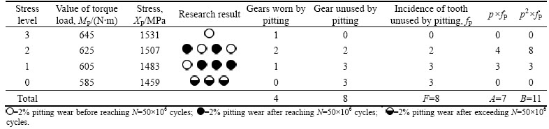
On the basis of the measurement results of the contact fatigue strength listed in Table 2, sHlim value and standard deviation S were calculated:
 (9)
(9)
 (10)
(10)
To plot the Wohler curve, the studies on a limited fatigue strength were taken and the results are listed in Tables 5 and 6.
Measurements of the reduced fatigue strength were performed on the nine pairs of gears. To designate a single point of Wohler curve, tests were repeated three times, with the same load, which caused the same contact stresses. The selected area of the active surface of the polished tooth with the critical pitting wear and the area before reaching this criterion for the shaved tooth are shown in Fig. 8.
Table 5 contact stresses measurement results in area of reduced fatigue strength for gears machined according to technique A (material-8620 steel)
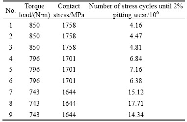
Table 6 contact stresses measurement results in area of reduced fatigue strength for gears machined according to technique B (material-8620 steel)
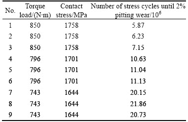
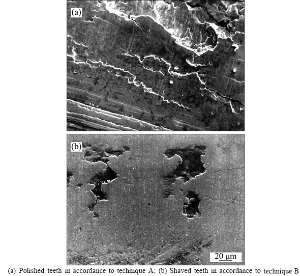
Fig. 8 Pitting cracks after fatigue tests:
The surface condition of the tooth shown in Fig. 8(a) is the result of the cyclic loads, which caused contact stress sH=1644 MPa with the number of cycles N=14.34��106 and after obtaining 2% pitting wear criterion. There are visible cracks in surface layer, which are oriented in accordance to the direction of grinding scratches formed during polishing. In this case, grinding scratches are unwanted concentrators of the stresses.
The surface condition of the tooth shown in Fig. 8(b) was achieved during fatigue tests in which contact stresses take the value sH=1644 MPa with the number of cycles N=14.34��106. In such conditions the pitting wear criterion was not obtained. This criterion was obtained with the contact stress sH=1644 MPa and after the number of stress cycles N=20.73��106. It can be noted that the crack are sort "autonomous" on the isotropic surface. These cracks do not cause further cracking, as those shown in Fig. 8(a). This kind of crack is much less harmful than crack connecting into larger grid visible on the polished tooth.
On the basis of long-term experimental studies with results given in Tables 1 to 4, the Wohler curve was plotted for the contact fatigue strength of the gear teeth made of the 8620 steel with the top layer constituted according to technologies A and B. Two curves for different technologies but for the same material are shown in Fig. 9.
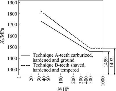
Fig. 9 contact fatigue strength for gear teeth made of 8620 steel
Based on the plotted Wohler curves, it is possible to evaluate both gear teeth finishing methods, taking into account the pitting wear resistance of the surface layer. Figure 9 shows directly that the finishing method according to technique B causes the greater contact fatigue strength than the finishing method according to technique A.
5 Conclusions
During investigations of characteristics of the surface layer and the contact strength of the gear teeth, the results of two finishing methods (technique A�� carburizing, hardening and teeth grinding; technique B��teeth shaving, carburizing and hardening) were compared. Results show that technique B is more favorable in terms of pitting wear resistance and properties of the surface layer, rather than technique A. By comparing the properties of the surface layer and the results of fatigue tests for these two technologies, it is possible to conclude.
1) The top layer constituted by technique B is characterized by a lower content of retained austenite and higher compressive residual stress, rather than by technique A, which is beneficial for the fatigue strength of the contact.
2) Fatigue tests on the test bench power circulating in the system have shown that the gears machined by technique B have higher contact fatigue strength sHlim. Also the service life of the wheels by the onset of signs of pitting according to the criterion 2% value is significantly higher than in the case of wheels made by the technique A.
3) Geometrical structure of the surface obtained after technique B is more advantageous in terms of volume distribution of voids in the material and the profile height function St. This feature affects the formation of the oil film thickness during operation of gears, lubricated with gear oil.
4) However, it should be mentioned that technique B can be used only for steel materials that exhibit a form fitting dimensional stability during hardening and tempering. Technique A has no limitations since the grinding process removes some errors in shapes and dimensions.
References
[1] CHEN Hai-feng, TANG Jin-yuan, ZHOU Wei. Modeling and predicting of surface roughness for generating grinding gear [J]. Journal of Materials Processing Technology, 2013, 213(5): 717-721.
[2] LV M, YANG X. Design and manufacture of a shaving cutter with unegual depth gashes [C]// Journal of Materials Processing Technology, 2002, 129(1/2/3): 193-195.
[3] NASER AMINI, ROSEN B G, Westberg H. Optimization of gear tooth surfaces [J]. Iternational Journal of Machine Tools and Manufacture, 1998, 38(5/6): 425-435.
[4] ASLANTAS K, TASGETIREN S, YALCIN Y. Austempering retards pitting failure in ductile iron spur gears [J]. Engineering Failure Analysis, 2004, 11: 935-941.
[5] ZWOLAK J. Some aspects of the construction-material-technology system design for toothed transmission working machines [D]. Cracow: Faculty of Mechanical Engineering and Robotics, University of Science and Technology, 2006.
[6] DUZCUKOGLU H, IMREK H. A new method preventing premature pitting formation on spur gears [J]. Engineering Fracture Mechanics, 2008, 75: 4431-4438.
[7] GLODEZ S, WINTER H, STUWE H P. A fracture mechanics model for the wear of gear flanks by pitting [J]. Wear, 1997, 208(1): 177-183.
[8] TANG Jin-yuan, LIU Yan-ping. Loaded muti-tooth contact analysis and calculation for contact stress of face-gear drive with spur involute pinion [J]. Journal of Central South University, 2013, 20: 354-362.
[9] HEINZEL C, WAGNER A. Fine finishing of gears with high shape accuracy [J]. CIRP Annals-Manufacturing Technology, 2013, 62(1): 359-362.
[10] OCZO K, LUBIMOV V. Geometric structure of the surface [M]. Rzeszow: Publishing house of the Rzeszow University of Technology, 2003.
[11] GURNEY T R. Fatigue of welded structures [M]. London: Cambridge University Press, 1979.
[12] DOMMARCO R C, KOZACZEK K J, BASTIAS P C, HAHN G T, RUBIN C A. Residual stresses and retained austenite evolution in SAE 52100 steel under non-ideal rolling contact loading. [J] Wear, 257(11): 1081-1088.
[13] ONISHCHENKO V. Tooth wear modeling and prgnostication parameters of engagement of spur gear power transmissions [J]. Mechanism and Machine Theory, 2008, 43(12): 1639-1664.
(Edited by YANG Hua)
Received date: 2015-03-02; Accepted date: 2015-05-23
Corresponding author: Jan Zwolak, Associate Professor, PhD; Tel: +48-178518582; E-mail: jazwol@ur.edu.pl
Abstract: This work presented the characteristics of two gear teeth finishing methods, due to the properties of gear teeth surface layer obtained at the tooth working depth. These methods are: 1) the teeth carburization, hardening to a hardness of HRC 60-62 and then grinding, 2) the soft gear shaving as the final mechanical treatment and then carburizing and hardening to the hardness of HRC60-62. This work included the test results of the contact fatigue strength carried out on the circulating power system. The Wohler curves were plotted due to the obtained results, as the basis for the practical evaluation of the considered gear finishing methods. The parameters like volume distribution of the voids, content of the retained austenite, compressive residual stress value, but also the results of contact fatigue strength tests, are more favorable for the teeth shaving method than for the teeth grinding method.
