

Morphology of alpha-lead dioxide electrodeposited on aluminum substrate electrode
CHEN Bu-ming(�²���), GUO Zhong-cheng(���ҳ�), YANG Xian-wan(������), CAO Yuan-dong(��Զ��)
Faculty of Metallurgical and Energy Engineering, Kunming University of Science and Technology,Kunming 650093, China
Received 13 August 2008; accepted 30 April 2009
Abstract:
Alpha-lead dioxide was deposited by anodization of alkaline solution containing HPbO2- anions. Scanning electron microscopy (SEM) results show that the morphology is remarkably affected by the current density, concentration of HPbO2- anions, bath temperature and electroplating time. Compact and well adherent layers are possibly obtained under conditions of current densities ��3 mA/cm2, electrolyte containing 4 mol/L NaOH and 0.12-0.14 mol/L lead (��), bath temperature of 40 ��, and electroplating time of 2 h. EDS analyses show that the PbO2 deposited in alkaline condition is highly non-stoichiometric at high current density.
Key words:
alpha-lead dioxide; morphology; electrodeposition; composition; aluminum substrate;
1 Introduction
Lead dioxides have been used frequently in industry because of their excellent properties such as good conductivity, low cost, high stability and relatively high service life. A great number of applications have been reported for lead dioxide as positive active material in lead acid batteries[1], oxidation of organic compounds in waste water[2-4], oxidation of glucose[5], ozone evolution[6-7], oxidation of phenol[8-9] and Cr3+[10].
The lead dioxide from electrodepositing is known to exist in two polymorphs: orthorhombic ��-lead dioxide and tetragonal ��-lead dioxide[11]. It is well known that the crystal structure of PbO2 deposits depends on the pH of the electroplating solution. Alpha-PbO2 is obtained from bases and ��-PbO2 from acids[11]. Alpha-PbO2, which results in better contact between particles, has a more compact structure than ��-PbO2. The more compact structure makes ��-PbO2 more difficultly discharged compared with ��-PbO2[12]. However, results from the work by R?ETSCHI[13] and FENG and JOHNSON[14] showed that ��-PbO2 had a higher catalytic activity than ��-PbO2 in dilute H2SO4 solution.
A new type of PbO2-coated metal anode has been widely used in electrolysis[10, 15]. This electrode is made up of four layers: the base is made of titanium plate, and covered with a conductive undercoating(being necessary for protecting the substrate from passivation) as bottom; the intermediate coating is composed of ��-PbO2 and plated wit ��-PbO2 as surface layer. Titanium is not a viable substrate for practical electrodes in electrodepositing of nonferrous metals. Aluminum is relatively cheap and has good conductivity. The electrode material by electrodepositing lead dioxide on A1 substrate has huge market prospects. A stress-free intermediate ��-PbO2 coating is produced by electrodeposition from an alkaline lead bath[16], which plays the role of binder on the top ��-PbO2 coating and can improve the serve life of electrode. However, the ��-PbO2 films deposited from basic solution were highly porous[17-18] and the research work was confined to the internal stress measurement[16].
Most of the previous studies on the morphology has concerned ��-polymorph[2, 19-20]. However, there is little research about the morphology of ��-PbO2 coating, and the structure of the intermediate coating is likely to be important for the lead-acid battery and as an electro-catalytic material for oxygen transfer reactions. In this work, ��-PbO2 films with different morphologies electrodeposited on aluminum substrate in alkaline bath were discussed. An analysis of cyclic voltammetry experiments with ��-PbO2 electrodes in alkaline and acid bath was also given, respectively.
2 Experimental
2.1 Preparation of PbO2/A1 anode
The PbO2/A1 anode was produced by applying ��-PbO2 to an A1 substrate with a conductive undercoating, followed by an intermediate coating consisting of ��-PbO2 deposit.
2.2 Application of coatings
The substrates were aluminum (or aluminum alloy) rods of d9 mm��60 mm, which were roughened by sand-blasting, degreased and chemically etched firstly, then coated by a conductive coating. The procedure was described as follows: firstly, the conductive solution was applied to the substrate by brushing; secondly, the substrate was surface dried under ultraviolet lamp, and finally dried in electricity box at 423 K for 2 h. The undercoating produced in this study was about 20-30 ?m thick, and the details were presented in Ref.[21]. Thereafter, the composition and process conditions of the PbO2 plating bath were shown as follows: 4 mol/L NaOH with litharge PbO(s) (the soluble Pb(��) species were HPbO2- anions), pH��14, anode current density of 1-5 mA/cm2, mild stirring using a magnetic stirrer, bath temperature of 25-55 ��, and electroplating time of 1-3 h.
2.3 Characterization of PbO2/A1 electrode
The electrochemical performance was measured by the three-electrode cell: A1/conductive coating/PbO2 anode as the working electrode, Hg/Hg2Cl2 (KC1, saturated) as the reference electrode, and a graphite as the auxiliary electrode. Cyclic voltammetric curves were measured in an alkaline and acid lead bath, respectively. The alkaline bath (called S1) contained 4 mol/L NaOH solution saturated with litharge PbO(s) at 25 �� in the potential range of 0-1.4 V. The acid bath (called S2) contained 30% Pb(NO3)2 (pH=1.5). The bath temperature was kept at 25 �� in the potential range of 0-2.1 V.
The surface morphology of the coatings was examined by SEM (XL30 ESEM, Philip, Holland). EDS(PHOENIX, EDAI,USA) was employed to analyze the crystalline composition of the films. The crystal size and structure of the films were analyzed by X-ray diffraction (XRD) with Co K�� radiation in a standard X-ray diffractometer. The thickness was measured by XJP-6A metalloscope.
3 Results and discussion
The cyclic voltammograms of A1/conductive coating/��-PbO2 electrode in basic solution S1(Fig.1(a)) and acid solution S2(Fig.1(b)) at a scan rate of 50 mV/s are shown in Fig.1. As shown in Fig.1(a), the potential of the beginning deposition of ��-PbO2 is higher than 0.25 V[10]. Two anodic current density peaks at ��p1=0.29 V and ��p2=0.49 V are observed on the positive branch of the cyclic voltammogram. These peaks probably correspond to the formation of Pb3O4 and PbO2, respectively. The cathodic current density peak is observed at approximately ��p3=0.10 V on the negative potential scan due to cathodic dissolution of PbO2 deposited during the previous positive scan[14]. The exponential growth of the anodic current density at potential over 1.0 V is due to oxygen evolution.
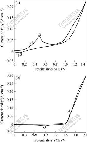
Fig.1 Cyclic voltammograms performed in different solutions with working electrode of A1/conductive coating/��-PbO2 at 50 mV/s: (a) Solution S1; (b) Solution S2
It is obvious from Fig.1(b) that the potential of the beginning deposition of ��-PbO2 is higher than 1.60 V. The anodic current density peak at ��p4=1.66 V is observed on the positive branch and the cathodic current density peak at ��p5=0.90V is observed on the negative branch. The anodic peak corresponds to the formation of surface lead dioxide or oxygen evolution and the cathodic peak is probably due to the formation of the oxidation of a soluble Pb(��).
3.1 Effect of current density
Fig.2 shows SEM images of deposited ��-PbO2 on A1/conductive coating electrode from solution containing 4 mol/L NaOH saturated with litharge PbO(s) at different current densities. The surface of PbO2 deposited at 1 mA/cm2 consists of crystals with large size and surface uniformity(Fig.2(a)). At current density of 2 mA/cm2 (Fig.2(b)), the PbO2 surface becomes more uniform, consisting of rod-like grains of 50-60 nm. Further increasing the current density, there are a large number of small crystals without clear crystal edges(Fig.2(c)). The film exhibits a fibre texture with good orientation and recrystallizes into the oriented fibre texture standing on surface layer of the formed film[18]. At current densities of 4 mA/cm2 or higher, however, the PbO2 films of the fibre texture are randomly oriented and are highly porous. A comparison between Fig.2(d) and (e) reveals that the clear crystal edges appear at current density of 4 mA/cm2. It is interesting that increasing current density from 1 to 5 mA/cm2 causes the decrease of the diameter of fibres by approximately 20 nm.
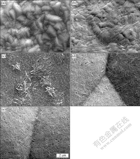
Fig.2 SEM images of ��-PbO2 prepared from 4 mol/L NaOH saturated with litharge PbO(s) on A1/conductive coating electrode at 40 �� for 2 h with different current densities: (a) 1 mA/cm2; (b) 2 mA/cm2; (c) 3 mA/cm2; (d) 4 mA/cm2; (e) 5 mA/cm2
This phenomenon may be explained as follows. The structure of the ��-PbO2 deposit maybe result from complexation of lead cation in the electrodeposition solution. It has been reported[18, 22] that PbO dissolves in alkaline solutions with the formation of HPbO2- and, to a less extent, polynuclear complexes. It seems probably that oxidation of such complexes can lead to polynuclear complexes containing PbO32-. The hydrolysis of such species, following oxidation at the electrode to precipitate ��-PbO2, is slow. At higher current densities, the solid oxide may precipitate at some distance from the electrode surface due to the increased concentration of the complexed Pb(��) cation. The agglomeration of such precipitates on the surface coatings can lead to a randomly oriented deposit. Also, a higher current causes the domination of oxygen evolution and, consequently, the formation of a series of
pores on the surface of anodic coating. At lower current densities, precipitation will take place near the electrode at a slower rate. There is enough time for the fibre texture to find the most suitable position and to form equilibrium state with the ��-PbO2 particles. The adsorption of anions on the crystallites may lead to the stability of ordered fibre structure. In addition, at lower current densities, most of current is used for the formation of ��-PbO2[23].
3.2 Effect of variables on electrodeposition of ��-PbO2
Fig.3 shows the effect of HPbO2- concentration on the morphology of ��-PbO2 coatings. The coatings were prepared from solutions containing 4 mol/L NaOH and 0.10-0.14 mol/L HPbO2-. As shown in Fig.3(a), a structure in leaves shape has been obtained at lower concentration of HPbO2- (0.10 mol/L). With increasing concentration up to 0.12 mol/L, a well-structured morphology has been obtained and the pore has not been found (Fig.3(b)). A further increase in HPbO2- concentration up to 0.14 mol/L results in the formation of larger PbO2 particles with clear crystal edges(Fig.3(c)). At lower HPbO2- concentrations, it seems that the mass transfer is a limiting step and the concentration polarization occurs on the electrode surface. At higher HPbO2- concentrations, mass transfer process is quick enough compared with electron transfer and a well-formed structure of electrodeposited surface has been obtained[24]. Also, with increasing HPbO2- concentration, the nucleation rate is correspondingly increased.
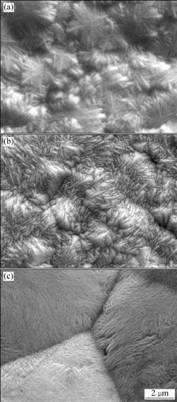
Fig.3 SEM images of PbO2 prepared at various concentrations of HPbO2- in solution containing 4 mol/L NaOH and 1.8 mA/cm2 on A1/conductive coating electrode at 40 �� for 2 h: (a) 0.10 mol/L; (b) 0.12 mol/L; (c) 0.14 mol/L
Fig.4 shows SEM images of PbO2 prepared from solution containing 4 mol/L NaOH solutions saturated with litharge PbO(s) at 2.5 mA/cm2 on A1/conductive coating electrode for 2 h at different temperatures. At a lower temperature(30 ��), a loose structure consisting of a big fibre texture with obvious boundaries is deposited on the surface of the electrode. At a higher temperature(40 ��), a higher adherence coating is obtained with a pronounced change in the morphology. Further increasing temperature to 50 �� results in the structure of similar pattern with well-distributed fibre textures and more clearly crystal edges. However, either very low temperature or very high temperature gives a lump deposit[25]. Therefore, the effect of temperature is probably due to a decrease of the potential for the onset of electrodeposition[26]. At relatively low potentials, the formation of polycrystalline assemblies is less probable and disorder effects are less common. Considering that the growth rate along different crystallographic directions may depend only slightly on temperature, preferred crystallographic orientations can become more pronounced at higher temperature, which is mainly due to the fact that the number of the polycrystalline assemblies on the electrode surface is small.
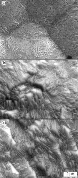
Fig.4 SEM images of PbO2 prepared at different temperatures in solution containing 4 mol/L NaOH solutions saturated with litharge PbO(s) at 2.5 mA/cm2 on A1/conductive coating electrode for 2 h: (a) 30 ��; (b) 40 ��; (c) 50 ��
Fig.5 shows the SEM images of lead dioxide deposited on A1/conductive coating electrode from 4 mol/L NaOH solutions saturated with litharge PbO(s) at 3 mA/cm2 for different plating time. As shown in Fig.5(a), rod-like grains of the fibre texture are obtained in a shorter deposition time(1 h). However, with the prolonging of time to 2 h(Fig.5(b)), a number of crystals with clear crystal edges and a few pores have been found. Further prolonging time to 3 h(Fig.5(c)) results in a great number of small crystals without clear crystal edges and many small pores. It is also found that the process of electrodeposition of a new phase at A1/conductive coating electrode involves the laying down of a number of nucleation centers followed by the growth of centers, which coalesce to form a complete layer of the new phase[11]. It is interesting to note that H+ ions are generated at the anode during PbO2 deposition. At the imposed current densities and under forced mass-transfer conditions, local pH in the basic solution is unlikely to become markedly lower than the original solution with the prolonging of time. However, the HPbO2- concentration decreases with increasing the plating time, and the nucleation rate is relatively decreased. A lower HPbO2- concentration is not high enough to contribute effectively in surface modification. The PbO2 coating with a few pores is obtained in a very long time of electrodeposition.
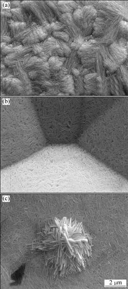
Fig.5 SEM images of PbO2 prepared in solution containing 4 mol/L NaOH solutions (40 ��) saturated with litharge PbO(s) at 3 mA/cm2 on A1/conductive coating electrode for different time: (a) 1 h; (b) 2 h; (c) 3 h
3.3 Compositional analysis
EDX was used for identification of each sample by liner sweep scanning of sample. The compositional analysis of ��-PbO2 electrodeposits was performed under different experimental conditions using energy dispersive X-ray analyzer (EDAX). EDAX spectra of PbO2 films deposited under different conditions are shown in Table1 and Fig.6. It is found from Table 1 that Pb contents also increase with the increase of HPbO2- concentration and the prolonging of the plating time. However, a remarkable change is obtained about the Pb content of ��-PbO2 film at different current densities. The Pb contents increase from 32.17% to 40.42% with current density form 1 mA/cm2 to 4 mA/cm2, and then decrease to 33.59% at the current density of 5 mA/cm2. It is also found the Pb content of ��-PbO2 film is higher at 40 ��. These results prove that the anodic layer is non-stoichiometric PbO2. This phenomenon may be explained as follows. H+ ions are generated at the anode during PbO2 deposition, which results in a decrease of the local pH at the interface. DELAHAY et al[22] showed that the solubility of Pb(��) exhibited a minimum at pH=9.4. Therefore, the local decrease of pH from a highly alkaline solution induces a decrease of the solubility of Pb(��) at the interface, and precipitation of lead hydroxide is possible from the concentrated plumbite solution[27]. On the other hand, a common feature should be noted that a porous morphology is favorable to increasing Pb contents of the PbO2 films. And highly porous film is normally formed at large current density or potential polarization. Such highly porous structure greatly increases effective area of PbO2 film.
Table 1 Compositional analysis of PbO2 films deposited under different conditions��molar fraction��%��
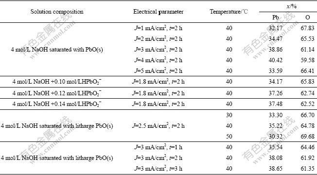
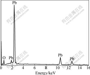
Fig.6 EDAX spectrum of PbO2 film
3.4 XRD identification
Since PbO2 can exist in two phases, XRD is used to identify the structure of electrodeposited PbO2. A typical XRD pattern of PbO2 deposited on A1/conductive coating electrode at constant current density of 2 mA/cm2 for 2 h in solution containing 4 mol/L NaOH solutions (40 ��) saturated with litharge PbO(s) is shown in Fig.7. In Fig.7, ��-PbO2 can be identified from its intense lines (002, at 38.16?), (200, at 42.28?) and (132, at 71.54?) and PbO from its intense line (320, at 68.2?). The XRD pattern of ��-PbO2 prepared from alkaline solution indicates the presence of PbO, but the characteristic peaks of ��-PbO2, remarked by Miller number, have not been observed. The impurity is attributed to the co-deposition of an insoluble Pb(��) compound from the alkaline plating solution containing lead hydroxide Pb(OH)2 or the oxide PbO.
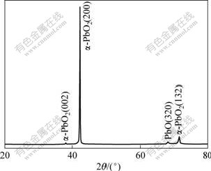
Fig.7 Typical XRD pattern of PbO2 prepared in solution containing 4 mol/L NaOH solutions (40 ��) saturated with litharge PbO(s) at 2 mA/cm2 on A1/conductive coating electrode for 2 h
4 Conclusions
1) The current density during the deposition of PbO2 has a strong influence on the morphology of the prepared film. A compact and uniform layer of lead dioxide is obtained at the current density not higher than 3 mA/cm2. A further increase in current density results in a smaller particle with a high porosity. The optimum current density is 2 mA/cm2.
2) The morphology and particle size distribution can be improved when the HPbO2- concentration is 0.12 mol/L and the bath temperature is 40 ��. However, ��-PbO2 coating with a few pores is obtained in a very long plating time.
3) It is found from EDS that the PbO2 deposited in alkaline conditions is highly non stoichiometric, which can be attributed to a porous behavior of deposited films. XRD pattern reveals that ��-PbO2 is dominated in the deposit.
References
[1] Pletcher D, Zhou Han-tao, Kear G, JohnLow C T, Walsh F C, Wills R G A. A novel flow battery��A lead-acid battery based on an electrolyte with soluble lead(II): Part VI. Studies of the lead dioxide positive electrode [J]. Journal of Power Sources, 2008, 180(1): 630-634.
[2] Mohd Y, Pletcher D. The fabrication of lead dioxide layers on a titanium substrate [J]. Electrochimica Acta, 2006, 52(3): 786-793.
[3] CHEN Bu-ming, GUO Zhong-cheng, YANG Xian-wan, ZHANG Jie-lei, LONG Jin-ming. Progress on electrodeposition of doped-PbO2 surface[J]. The Chinese Journal of Nonferrous Metals, 2008, 18 (9):1711 -1720. (in Chinese)
[4] Liu Yuan, Liu Hui-ling, Li Yan. Comparative study of the electrocatalytic oxidation and mechanism of nitrophenols at Bi-doped lead dioxide anodes [J]. Applied Catalysis B: Environmental, 2008, 84(1/2): 297-302.
[5] Hyde M E, Jacobs R M J, Compton R G. An AFM study of the correlation of lead dioxide electrocatalytic activity with observed morphology [J]. J Phys Chem B, 2004, 108: 6381-6390.
[6] Amadelli R, Battisti A D, Girenko D V, Kovalyov S V, Velichenko A B. Electrochemical oxidation of trans-3, 4-dihydroxycinnamic acid at PbO2 electrodes: Direct electrolysis and ozone mediated reactions compared [J]. Electrochimica Acta, 2000, 46(2/3): 341-347.
[7] Wang Jing-ping, Li Xiang, Guo Ling-hua, Luo Xiang-jun. Effect of surface morphology of lead dioxide particles on their ozone generating performance [J]. Applied Surface Science, 2008, 254(20): 6666-6670.
[8] Iniesta J, Gonz��lez-Garc��a J, Exp��sito E, Montiel V, Aldaz A. Influence of chloride ion on electrochemical degradation of phenol in alkaline medium using bismuth doped and pure PbO2 anodes [J]. Water Research, 2001, 35(14): 3291-3300.
[9] Andrade L S, Rocha-Filho R C, Bocchi N, Biaggio S R, Iniesta J, Garc��a-Garcia V, Montiel V. Degradation of phenol using Co- and Co, F-doped PbO2 anodes in electrochemical filter-press cells [J]. Journal of Hazardous Materials, 2008, 153(1/2): 252-260.
[10] Devilliers D, Dinh-Thi M T, Mah�� E, Xuan Q L. Cr(III) oxidation with lead dioxide-based anodes [J]. Electrochimica Acta, 2003, 48(28): 4301-4309.
[11] Carr J P, Hampson N A. The lead dioxide electrode [J]. Chemical Reviews, 1972, 72(6): 679-702.
[12] Petersson I, Ahlberg E, Berghult B. Parameters influencing the ratio between electrochemically formed ��- and ��-PbO2 [J]. Journal of Power Sources, 1998, 76(1): 98-105.
[13] R��etschi P. Influence of crystal structure and interparticle contact on the capacity of PbO2 electrodes [J]. Journal of Electrochemical Society, 1992, 139(5): 1347-1351.
[14] Feng J, Johnson D C. Electrocatalysis of anodic oxygen-transfer reactions: alpha-lead dioxide electrodeposited on stainless steel substrates [J]. Journal of Applied Electrochemistry, 1990, 20: 116-124.
[15] Ueda M, Watanabe A, Kameyama T, Matsumoto Y, Sekimoto M, Shimamune T. Performance characteristics of a new type of lead dioxide-coated titanium anode [J]. Journal of Applied Electrochemistry, 1995, 25: 817-822.
[16] Fukasawa A, Ueda M. Electrodeposited lead dioxide layers having no internal stress [J]. Journal of Electrochemical Society, 1976, 44(1): 646-651. (in Japanese)
[17] Campbell S A, Peter L M. Determination of the density of lead dioxide films by in situ laser interferometry [J]. Electrochimica Acta, 1987, 32(2): 357-360.
[18] Campbell S A, Peter L M. A study of the effect of deposition current density of the structure of electrodeposited ��-PbO2 [J]. Electrochimica Acta, 1989, 34(7): 943-949.
[19] Ghasemi S, Mousavi M F, Shamsipur M. Electrochemical deposition of lead dioxide in the presence of polyvinylpyrrolidone: A morphological study [J]. Electrochimica Acta, 2007, 53(2): 459-467.
[20] Mehdinia A, Mousavi M F, Shamsipur M. Nano-structured lead dioxide as a novel stationary phase for solid-phase microextraction [J]. Journal of Chromatography A, 2006, 1134(1/2): 24-31.
[21] GUO Zhong-cheng. Preparation method of energy saving and inert anodic material for non-ferrous metals electrowinning: CN, 200810058194.5[P]. 2008-03-15.
[22] Delahay P, Pourbaix M, Rysselberghe P V. Potential��pH diagram of lead and its applications to the study of lead corrosion and to the lead storage battery [J]. Journal of Electrochemical Society, 1951, 98(2): 57-64.
[23] Ghasemi S, Karami H, Mousavi M F, Shamsipur M. Synthesis and morphological investigation of pulsed current formed nano-structured lead dioxide [J]. Electrochemistry Communications, 2005, 7(12): 1257-1264.
[24] Shen Pei-kang, Wei Xiao-lan. Morphologic study of electrochemically formed lead dioxide [J]. Electrochimica Acta, 2003, 48(12): 1743-1747.
[25] Gnanasekaran K S A, Narasimham K C, Udupa H V K. Stress measurements in electrodeposited lead dioxide [J]. Electrochimica Acta, 1970, 15(10): 1615-1622.
[26] Velichenko A B, Amadelli R, Benedetti A, Girenko D V, Kovalyov S V, Danilov F I. Electrosynthesis and physicochemical properties of PbO2 films [J]. Journal of Electrochemical Society, 2002, 149(9): C445-C449.
[27] Devilliers D, Dinh-Thi M T , Mah�� E, Dauriac V, Lequeux N. Electroanalytical investigations on electrodeposited lead dioxide [J]. Journal of Electroanalytical Chemistry, 2004, 573(2): 227-239.
Foundation item: Project(20050053) supported by Foundation for the Author of National Excellent Doctoral Dissertation of China
Corresponding author: GUO Zhong-cheng; Tel: +86-871-8352598; E-mail: guozhch@vip.163.com
DOI: 10.1016/S1003-6326(09)60103-5
